
Related Manuals for E+E Elektronik EE220


Summary of Contents for E+E Elektronik EE220
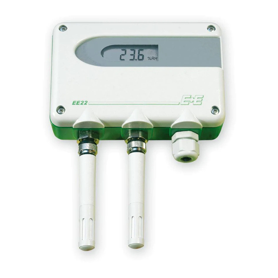
- Page 1 Operating Instructions EE220 Humidity / Temperature Transmitter BA_EE220_e // v3.2 // Technical data subject to change // 193532...
- Page 2 E+E Elektronik® Ges.m.b.H. provides no warranty of any kind for this publication and accepts no liability for improp- er use of the products described. This publication might contain technical inaccuracies or typographical errors. The content is revised regularly and is not subject to change management.
-
Page 3: Table Of Contents
Connecting the EE07 sensing probes ......................6 4.2.1 EE07 probes connected directly to EE220 ......................6 4.2.2 EE07 probes connected to EE220 with extension cables ..................7 4.2.3 EE07 duct mounted .............................7 Probe Protection During Cleaning and Sterilizing operations ............7 5.2.1 Probe protection ..............................7... -
Page 4: General
The operation manual may not be used for the purposes of competition without the written consent of E+E Elektronik® and may not be forwarded to third parties. Copies may be made for internal purposes. -
Page 5: Environmental Aspects
One or two point adjustment for RH and T of the transmitter can be easily performed with push buttons on the electronics board of the EE220 basic unit. Alternatively, the EE07 probes can be adjusted individually with the EE-PCA Product Configuration Adapter (see EE07 data sheet). -
Page 6: Installation
In order to avoid misreading caused by self-heating, the device shall be installed with the probes pointing downwards. In very humid, condensing environment it is recommended to use the EE220 version with remote probe, please see below. Operating instructions for EE220 humidity / temperature transmitter... -
Page 7: Ee07 Probes Connected To Ee220 With Extension Cables
The EE07 probe may not be grounded; it must be electrically isolated from the GND. • Locate the EE220, the probe cable and the output cables as far as possible from sources of electromagnetic disturbances. -
Page 8: Connection Diagram
• reset to factory calibration Display 1. CAL 1. CAL: • indicates adjustment mode 2. °C / °F 2. °C / °F: • T measuring unit 3. %RH 3. % RH: • RH measuring unit Operating instructions for EE220 humidity / temperature transmitter... -
Page 9: Rh And T Adjustment Of The Ee07 Probes
(14 °F) (59 °F) • The adjustment data is saved into the EE07 probes. The EE220 basic unit is not affected by the adjustment procedure. Consequently, it is possible to replace the probes at any moment. • Start the adjustment procedure with the low point (e.g. 30 % RH) and continue with the high point (e.g. -
Page 10: 1-Point Rh And T Adjustment
3. For adjustment point in the lower half of the output scale, press and hold S2 for 3 seconds. The LED “Calib” will light and the symbol “CAL<” will appear on the EE220 display. For adjustment point in the upper half of the output scale, press and hold S1 for 3 seconds. -
Page 11: Loop Adjustment And Calibration In The Field
The set includes a test report for each reference probe. For EE220 basic unit dedicated for only one combined EE07 RH & T probe, both RH and T check shall be performed with each reference probe connected at the single probe connection socket. -
Page 12: Ee220 Check Using The Display
If the EE220 basic unit features a display, as soon as the reference probe is connected the display shall show the corresponding RH and T reference values. If the EE220 basic unit does not feature a display, it is easily possible to plug in a display (see chapter “12. EE220 Display Replacement or Retrofit”). It is highly advisable to keep a spare display specifically for this purpose or for easy adjustment of the entire EE220 including EE07 probes (see chapter “8.2. -
Page 13: Ee03 Humidity And Temperature Module
S1 and S2 push buttons have no function. An EE03 deemed faulty shall be replaced against a new one. 11 Replacement of the Probes A damaged probe can be replaced by a new one without any EE220 setup change or re-adjust- ment, as follows: 1. Switch off supply voltage 2. -
Page 14: Spare Parts And Accessories
3. For replacing an existing display: remove the exiting display by pulling it straight upwards. The display plugs easily off the main EE220 electronics board. 4. Place the display connecting leads onto the sockets on the main electronic board while observing its orientation (Fig. -
Page 15: Technical Data Ee220
Industrial Environment Working temperature range basic unit -40...60 °C (-40...140 °F) Storage temperature range -40...60 °C (-40...140 °F) For technical data EE07 and EE03 please see the corresponding data sheets at www.epluse.com. Operating instructions for EE220 humidity / temperature transmitter... - Page 16 COMPANY HEADQUARTERS TECHNICAL OFFICES E+E ELEKTRONIK Ges.m.b.H. E+E CHINA www.epluse.com www.epluse.cn E+E ITALY Langwiesen 7 BEIJING www.epluse.it A-4209 Engerwitzdorf Tel: +86 10 84992361 Tel: +39 02 2707 8636 Austria info@epluse.cn info@epluse.it Tel: +43 7235 605 0 SHANGHAI Fax: +43 7235 605 8 Tel: +86 21 61176129 info@epluse.com...
Need help?
Do you have a question about the EE220 and is the answer not in the manual?
Questions and answers