Table of Contents
Advertisement
Quick Links
USER'S GUIDE
EE210 - Humidity and Temperature Transmitter for
demanding Climate Control Applications
GENERAL
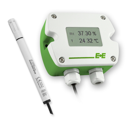
The EE210 transmitter, available for wall or duct mounting as well as with remote probe, is designed for highly accurate
measurement of humidity and temperature in demanding climate control applications. The EE210 incorporates the E+E humidity and
temperature sensor HCT01.
For use in special applications do not hesitate to contact E+E Elektronik or a local distributor.
CAUTION
•
For accurate measurement it is essential that the temperature of the sensing probe and mainly of the sensing head is same as
the temperature of the air to measure. Avoid mounting the transmitter in a way which creates temperature gradients along the
probe.
•
The transmitter and mainly the sensing head shall not be exposed to extreme mechanical stress.
•
The transmitter must be operated with the filter cap on at all times. Do not touch the sensors inside the sensing head.
•
While replacing the filter cap (because of pollution for instance) against an original spare one please take very good care to
not touch the sensors.
DIMENSIONS / MOUNTING
Type A
90
mm
±0.3
3.54
±0.11
"
5mm
0.2"
Recommended mounting screws:
ST4.2x50 DIN7981C
Type C
EE210 with cable gland: Use a matching wrench to install the cable gland (in the scope of supply) onto the EE210 enclosure.
EE210 with conduit connection for the North American market: use a flat screwdriver to knock open the blind, carefully, in order
to avoid damaging the electronics inside the enclosure. The conduit adapter is not included in the scope of supply. The M16x1.5
opening for the cable gland shall be tightly closed using the blind plug included in the scope of supply.
FOR CONDUIT
INSTALLATION
CABLE GLAND M16x1.5
Ø 12mm
Ø 0.47"
EE210P
Type B
90
mm
±0.3
3.54
"
±0.11
Ø > 13mm
Ø > 0.51"
GASKET
19mm
0.75"
60
±0.3
mm
2.36
"
±0.11
Ø > 16mm
Ø > 0.63"
6mm
0.24"
Advertisement
Table of Contents

Related Manuals for E+E Elektronik EE210


Summary of Contents for E+E Elektronik EE210
- Page 1 EE210P EE210 with cable gland: Use a matching wrench to install the cable gland (in the scope of supply) onto the EE210 enclosure. EE210 with conduit connection for the North American market: use a flat screwdriver to knock open the blind, carefully, in order to avoid damaging the electronics inside the enclosure.
-
Page 2: Connection Diagram
Bus termination resistor 120 Ω (jumper) confi guration connector EE210P (type C) The EE210P remote probe for EE210-HTxxPC shall be ordered and it is supplied as separate item. EE210P is to be connected to the EE210 by the user. •... -
Page 3: Led Indication
The output signal (voltage or current 3-wire) can be selected with the DIP switch on the main electronics board (see picture PCB EE210-HT2/3/5). This does not impact on the scaling of the outputs, which can be changed using EE-PCA and EE-PCS. -
Page 4: Modbus Setup
The Firmware version is located at register address 30009 (Bit 15...8 = major release; Bit 7...0 = minor release). The choice of measurement units (metric or not metric) must be done in the ordering guide, see EE210 data sheet. Switching from metric to non metric or vice versa by using the EE-PCS is not possible. - Page 5 1 USA & Canada: class 2 supply required, max. supply voltage 30 V SETUP AND ADJUSTMENT The EE210 transmitter is ready to use and does not require any confi guration by the user. The factory setup of EE210 corresponds to the type number ordered. (Ordering guide please see data sheet at www.epluse.com/EE210.) If needed, the user can change the factory setup by using the optional E+E Product Configuration Adapter (EE-PCA) and the E+E Product Configuration Software (EE-PCS).
- Page 6 EE-PCA and EE-PCS against a reference of his choice, it is highly recommended to return the device to the manufacturer for this. The reasons rest on the difficulty of an accurate T calibration in the air. The calibration shall take into account the self-heating of EE210 with closed enclosure, in its real mounting position and in continuous operation, the impact of the output current and of the probe orientation to the self-heating, as well as the cooling effect of the air circulation in a climate chamber possibly used for calibration.
Need help?
Do you have a question about the EE210 and is the answer not in the manual?
Questions and answers