Table of Contents
Advertisement
Advertisement
Table of Contents

Subscribe to Our Youtube Channel
Related Manuals for GASTRON GTD-2000TxW


Summary of Contents for GASTRON GTD-2000TxW
- Page 1 GTD-2000TxW Instruction Manual Read in detail for correct use.
- Page 2 GTD-2000TxW Instruction Manual Gas & Flame Detection System In case of a problem after purchasing the product, please contact the address below. ·Address : 23 Gunpo Advanced Industry 1-ro, Gunpo-si, Gyeonggi-do ·Tel : 031-490-0800 ·Fax : 031-490-0801 ·URL : www.gastron.com ·e-mail...
- Page 3 Thank you very much for purchasing a product from Gastron Co. Ltd. Our Gastron Co.Ltd. is a company specialized in Gas Detector & Gas Monitoring System and have been recognized by many customers for the best quality and use convenience. We always seek to help our customers to find the product they need and we continuously research to develop gas detectors that satisfies our customers.
-
Page 4: Table Of Contents
GTD-2000TxW Contents Instruction Manual Overview · · · · · · · · · · · · · · · · · · · · · · · · · · · · · · · · · · · · · · · · · · · · · · · · · · · · · · · · · · · · · · · · · · · · · · · · · · · · · · · · · · · · · · · · · ·... - Page 5 Contents www.gastron.com 04_05 7.2. CALIBRATION MODE · · · · · · · · · · · · · · · · · · · · · · · · · · · · · · · · · · · · · · · · · · · · · · · · · · · · · · · · · · · · · · · · · · · · · · · · · ·...
-
Page 6: Overview
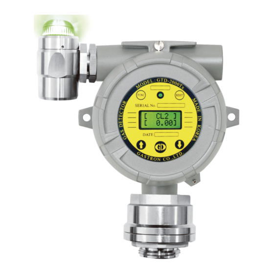
2. Configuration Body of GTD-2000TxW is made of Aluminum alloy and the gas sensor module is made of stainless steel. It consists of a complete explosion-proof enclosure (Ex d IIC T6). This product can be installed in areas with flammable gas leak and explosion hazards. -
Page 7: Specification
3. Specifications www.gastron.com 06_07 3.1. Basic Specifications ITEMS SPECIFICATION Measuring Type Diffusion - LCD or OLED Display Measuring Value Display - Green, Red, Yellow LED - Sound Output(95dB) - Electro-Chemical Cell Measuring Method - Heated-semiconductor Cell) - Photoionization detector(PID) Detectable Gas... -
Page 8: Electrical Specifications (Standard Type)
GTD-2000TxW 3. Specifications Instruction Manual 3.3. Electrical Specifications (Standard Type) ITEMS SPECIFICATION Input Voltage(Standard) Absolute min: ※ Customer supplied PSU must meet Nominal: requirements IEC1010-1 and CE Absolute max: Marking requirements. Ripple maximum allowed: 1V pk-pk Max. wattage: 3.6W @+24 VDC Wattage Max. -
Page 9: Name And Description Of Each Part
4. Name and Description of Each Part www.gastron.com 08_09 4.1. Components [Figure 2. GTD-2000TxW Components] ITEMS SPECIFICATION Housing Body Protects PCB Board built in Sensor and Housing from external environmental change and shock. It is assembled with Detector Housing Body. - Page 10 It serves to fix parts to the compliment part. CABLE WIRE It supplies power and transmits data. [Table 1. GTD-2000TxW 구성요소 설명] 4.2. LAMP 기능설명 ■ In normal status, green LED lights on and buzzer does not ring. ■ When Alarm-1 signal is received, red LED flickers in 1 sec interval and buzzer rings in 1 sec interval.
-
Page 11: Installation
5. Installation www.gastron.com 10_11 It is prohibited for an individual, other than an approved user or a technician responsible for installation and repair from the head office, to install a gas leak detector on site or open the cover of the installed gas leak detector and manipulate it. -
Page 12: Main Pcb Configuration
GTD-2000TxW 5. Installation Instruction Manual 5.2. Main PCB Configuration ■ After detaching the display parts, the Main PCB terminal layout appears as shown in the figure below. [Figure 5. Main PCB Terminal Layout] NAME DESCRIPTION Power & Output Signal Terminal... -
Page 13: Terminal Configuration
EARTH [Table 3. CN9 Terminal Detailed Description] ■ Use CVVS or CVVSB 2.0sq↑ Shield Cable for terminal configuration. ■ To connect 4 Pin terminal from the existing old GTD-2000TxW model, connect terminals in reference to pin #2, which is +24V. -
Page 14: Wiring For 4~20Ma Source Operation Type
GTD-2000TxW 5. Installation Instruction Manual 5.3.1. Wiring for 4~20mA Source Operation Type ■ Connect 4-20 mA signal terminal at PLC side to 'mA' of GTD-2000Tx. GND terminal is used in common with power. Then, turn on the J1 jumper. ■ HART Communicator can only be used in models using HART Option board. -
Page 15: Wiring For 4~20Ma 3Wire Sink Operation Type
[Figure 9. 4-20mA 3Wire Sink Configuration] 5.4. Installation Cable Length ■ The maximum length between GTD-2000TxW and power supply is decided by wire specification. ■ Max. Installation Length = VMAXDROP ÷ IMAX ÷ WIRER/m ÷ 2 ·VMAXDROP: Maximum Power Loop Voltage Drop (=Power Supply voltage - min operating voltage) ·IMAX : Max. - Page 16 GTD-2000TxW 5. Installation Instruction Manual [Figure 10. Calculation of GTD-2000TxW Installation Cable Length] ■ Power cable installation for each cable type is as shown in the table below. COPPER RESISTANCE(ohms/m) METERS 3.31 0.00521 3838 2.08 0.00828 2415 1.31 0.01318 1517 0.82...
-
Page 17: Detector Operation Flow
6. Detector Operation Flow www.gastron.com 16_17 6.1. Initial Operation Status (Power On) ■ After wiring to power terminal at the top of Main PCB board then supply power, the following contents are displayed on LCD. Approx. 30 min of stabilization of time is needed from the initial supply of operation power and it starts to operate normally after sufficient stabilization. -
Page 18: Operation Flow
■ When "RESET: key contacts at Program Mode Screen, it returns to Measuring Mode. When "RESET" key contacts at each Program Setting Screen, it returns to the parent step. [Figure 11. GTD-2000TxW Mode Configuration] ■ Operation keys for detector system mode are defined as below. -
Page 19: Menu Configuration Table
6. Detector Operation Flow www.gastron.com 18_19 6.4. Menu Configuration Table LEVEL2 LEVEL1 DEFAULT NAME PARAMETER GAS TYPE (Gas Type) [DEFIN./USER] DEFIN. GAS SEL(Gas Select) Built-in gas name selection COMB. UNIT SEL (Unit Select) %/%LEL/PPM/PPB %LEL PROGRAM MODE D-POINT(Decimal Point) 0.100/1.00/10.0/100... -
Page 20: System Mode
GTD-2000TxW 7. System Mode Instruction Manual 7.1. PROGRAM MODE PASSWORD - Contacting "FUNC" key with the Magnet-bar for 2 sec or longer in Measuring Mode enters Password mode. [**] - After setting Password using "↑" or "↓" key, contact "FUNC" key. -
Page 21: Calibration Mode
7. System Mode www.gastron.com 20_21 7.2. CALIBRATION MODE ■ Due to characteristics of the gas detector, minimum 30min of stabilization time is required and maintenance condition may change depending on site condition. 7.2.1. Zero Calibration - Contacting "FUNC" key with the Magnet-bar for 2 sec or longer in Measuring Mode enters Password PASSWORD mode. -
Page 22: Span Calibration
GTD-2000TxW 7. System Mode Instruction Manual 7.2.2. Span Calibration - Contact "↑" or "↓" key to select "Calibration Mode". CALIBRA. - Contact "FUNC" key when "CALIBRA. MODE" is displayed to enter Calibration Mode. MODE - Contact "RESET" key to return to Measuring Mode. -
Page 23: Alarm Mode
7. System Mode www.gastron.com 22_23 7.3. ALARM MODE PASSWORD - Contacting "FUNC" key with the Magnet-bar for 2 s or longer in Measuring Mode enters Password mode. [**] - After setting Password using "↑" or "↓" key, contact "FUNC" key. - Page 24 GTD-2000TxW 7. System Mode Instruction Manual A2 TYPE - It is a mode that sets operational direction of Alarm2. Contact "↑" or "↓" key to display "INC" or "DEC". [INC] - "INC" mode operates when the value is equal or larger than set alarm threshold. "DEC" mode operates when the value is equal or less than set alarm threshold.
-
Page 25: Troubleshooting
8. Troubleshooting www.gastron.com 24_25 8.1. Fault List FAULT MESSAGE DESCRIPTION & CONDITION CAUSE FAULT2 Defective sensor module or transmitter board Sensor output is above ADC max. value. "SEN HIGH" FAULT3 Defective sensor module or transmitter board Toxic sensor output is below ADC min. value. -
Page 26: Drawings And Dimensions
GTD-2000TxW 9. Drawings and Dimensions Instruction Manual 9.1. Standard Type [Figure 12. GTD-2000TxW Standard Type Drawing]... -
Page 27: Warning Light Gtl-100
9. Drawings and Dimensions www.gastron.com 26_27 9.2. Warning Light GTL-100 [Figure 13. GTL-100 Drawing]... -
Page 28: When Connecting Warning Light
GTD-2000TxW 9. Drawings and Dimensions Instruction Manual 9.3. When Connecting Warning Light [Figure 14. GTD-2000TxW Warning Light Connection Drawing]... -
Page 29: Precautions Before Installation
10. Precautions before Installation www.gastron.com 28_29 10.1. Selecting a Place for Installation (Occupational Health & Safety Act Data) A gas leak detector alarm shall be installed in the following places. ■ Around chemical equipment and accessories that have concerns of gas leak. This includes compressors, valves, reactors, pipe joints, etc. - Page 30 GTD-2000TxW 10. Precautions before Installation Instruction Manual ■ During wiring work, use explosion-proof cable gland at cable inlet or tightly seal cable conduit during metal cable wiring construction to prevent spread of flames in case of explosion or movement of gas, etc. through the cable conduit within 50 mm.
-
Page 31: Revision History
11. Revision History www.gastron.com 30_31 VERSION CONTENTS DATE * Manual Initial Revision 2017.09.29... - Page 32 Headquarters / Engineering research laboratory : 23 Gunpo Advance d Industry 1-ro(Bugok-dong), Gunpo-si, Gyeonggi-do Tel +82-31-490-0800 Fax +82-31-490-0801 Yeongnam business office / Plant : 55 Gonghangap-gil 85beon-gil, Gangseogu, Busan Metropolitan City Tel +51-973-8518 Fax +51-973-8519 E-mail : info@gastron.com www.gastron.com...
Need help?
Do you have a question about the GTD-2000TxW and is the answer not in the manual?
Questions and answers