Table of Contents
Advertisement
Quick Links
Advertisement
Table of Contents

Related Manuals for GASTRON GTD-1000Tx


Summary of Contents for GASTRON GTD-1000Tx
- Page 1 GTD-1000Tx Instruction Manual Read in detail for correct use.
- Page 2 GTD-1000Tx Instruction Manual Gas & Flame Detection System When abnormalities occur after purchasing the product, please contact the following address. ·Address : 23 Gunpo Advanced Industry 1-ro, Gunpo-si, Gyeonggi-do ·Tel : 031-490-0800 ·Fax : 031-490-0801 ·URL : www.gastron.com ·e-mail : info@gastron.com...
- Page 3 Gas detectors satisfying customers. From now on, solve all anguishes concerning Gas detector with the products of Gastron Co. Ltd, We Gastron Co. will take a responsibility and give you satisfaction. In the present instruction manual, operation method for Gas detector as well as simple methods for maintenance and repair, etc.
-
Page 4: Table Of Contents
GTD-1000Tx Contents Instruction Manual Overview · · · · · · · · · · · · · · · · · · · · · · · · · · · · · · · · · · · · · · · · · · · · · · · · · · · · · · · · · · · · · · · · · · · · · · · · · · · · · · · · · · · · · · · · · · ·... - Page 5 Contents www.gastron.com 04_05 9. Revision History · · · · · · · · · · · · · · · · · · · · · · · · · · · · · · · · · · · · · · · · · · · · · · · · · · · · · · · · · · · · · · · · · · · · · · · · · · · · · · · · · · ·...
-
Page 6: Overview
2. Configuration Body of GTD-1000Tx is made of Aluminum alloy and the gas sensor module is made of stainless steel. It consists of a complete explosion-proof enclosure (Ex d IIC T6). This product can be installed in areas with potential combustible gas leak and explosion hazards and internal structure consists of 1 PCB board with display part for measurements and terminal part that outputs measurements (DC 4 - 20 mA) externally. -
Page 7: Specification
3. Specification www.gastron.com 06_07 3.1. Basic Specifications ITEMS SPECIFICATION Measuring Type Diffusion - Electro-Chemical Cell Measuring Method - Heated-semiconductor Cell Detectible Gas Toxic Gas (Note1) Measuring Range Capable to display 000.0 ~ 9999 (Note 1) Accuracy ≤ ±3% / Full Range Zero Drift ≤... -
Page 8: Electrical Specifications (Standard Type)
GTD-1000Tx 3. Specification Instruction Manual 3.3. Electrical Specifications (Standard Type) ITEMS SPECIFICATION Input Voltage(Standard) Absolute min: ※ Customer supplied PSU must meet Nominal: requirements IEC1010-1 and CE Absolute max: Marking requirements. Ripple maximum allowed: 1V pk-pk Max. wattage: 3.6W @+24 VDC Wattage Max. -
Page 9: Name And Description Of Each Part
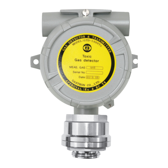
(Default specification is PF 3/4".) Mount holes(2-Ø7) Hole to fix the gas detector on external wall or other installation sites. Sensor terminal CN1 is Sensor Connection Terminal. Model name plate Model name, measuring gas, serial number, etc. are labeled. [Table 1. GTD-1000Tx Components Description]... -
Page 10: Installation
GTD-1000Tx 5. Installation Instruction Manual ■ It is prohibited for an individual, other than an approved user or a technician responsible for installation and repair from the head office, to install a gas leak sensor on site or open the cover of the installed gas leak sensor and manipulate it. -
Page 11: Main Pcb Configuration
5. Installation www.gastron.com 10_11 5.2. Main PCB Configuration ■ After detaching the cover, the Main PCB terminal layout appears as shown in the figure below. Figure 4. Main PCB Key Layout NAME DESCRIPTION Program download Connector Zero Calibration Switch Span Calibration Switch... -
Page 12: Power Signal And Terminal Configuration
GTD-1000Tx 5. Installation Instruction Manual 5.3. Power and Signal Terminal Configuration ■ After disassembling display parts, there is a terminal block in the Main PCB as shown in the figure below. Holding it with hands and pulling towards ceiling detaches it from the Main PCB. -
Page 13: Method To Connect To External Control Unit
5. Installation www.gastron.com 12_13 5.4. Method to Connect to External Control Unit ■ Connect 18 V~31 V DC operation power to CN1 (+, mA, -, ET) Connection Terminal of the gas detector then connect a device that can receive 4~20 mA signals to mA. -
Page 14: Installation Cable Length
·WIRER/m: The resistance of the wire (ohms/meter value available in wire manufacturer's specification data sheet) ■ Example of installation lengths using 24 V power supply and 16 AWG is as follows. ·GTD-1000Tx minimum operating voltage = 18 Vdc ·VMAXDROP = 24 - 18 = 6V ·IMAX = 0.15A( 150mA ) -
Page 15: Calibration And Maintenance
6. Calibration and Maintenance www.gastron.com 14_15 ■ Stabilization time of 30 min from the initial supply of operation power to the sensor for the stabilization of the sensor. Calibration and test must be performed approx. 30 min after when the sensor has been stabilized. -
Page 16: Span Calibration
GTD-1000Tx 6. Calibration and Maintenance Instruction Manual [Figure 9. ZERO Calibration related Parts] 6.3. SPAN Calibration ■ Check voltage of 18~31 V DC at both (+24 V) and (GND) of terminal block 'CN5'. ■ Check whether (mA) terminal of terminal block 'CN5’ is connected to the receiver. - Page 17 6. Calibration and Maintenance www.gastron.com 16_17 [Figure 10. Span Calibration related Parts] ■ Ex.) Output Calculation Method for NH3 Range : 0-150ppm Calibration gas : 100ppm NH balance Output signal : 4-20mA Test point signal ( TP5, TP6 ) 100ppm NH (Standard Gas) (200 - 40) ×...
-
Page 18: Drawings And Dimensions
GTD-1000Tx 7. Drawings and Dimensions Instruction Manual [Figure 11. GTD-1000Tx Drawing]... -
Page 19: Precautions Before Installation
8. Precautions before Installation www.gastron.com 18_19 8.1. Selecting a Place for Installation (Occupational Health & Safety Act Data) A gas leak detector alarm shall be installed in the following places. ■ Around chemical equipment and accessories that have concerns of gas leak. This includes compressors, valves, reactors, pipe joints, etc. - Page 20 GTD-1000Tx 8. Precautions before Installation Instruction Manual ■ Installation Height: 1,000 M below sea level ■ Relative Humidity: 5% ~ 99% ■ Installation Site: Indoor and Outdoor ■ Explosion Ignition Grade for the Gas or Vapor: Ex d IIC T6 ■...
- Page 21 9. Revision History www.gastron.com 20_21 VERSION CONTENTS DATE * Manual Initial Revision 2013.06.09 * Gas calibration method changed 2014.09.19 * mA Calibration Mode added 2014.10.24 * Changed Font 2014.12.26 * Separated Factory mode manual 2016.09.09 * Changed Explosion-proof Equipment Cable Entry Installation Regulation 45 cm → 50 mm...
- Page 22 Headquarters / Engineering research laboratory : 23 Gunpo Advance d Industry 1-ro(Bugok-dong), Gunpo-si, Gyeonggi-do Tel +82-31-490-0800 Fax +82-31-490-0801 Yeongnam business office / Plant : 55 Gonghangap-gil 85beon-gil, Gangseogu, Busan Metropolitan City Tel +51-973-8518 Fax +51-973-8519 E-mail : info@gastron.com www.gastron.com...
Need help?
Do you have a question about the GTD-1000Tx and is the answer not in the manual?
Questions and answers