Table of Contents
Advertisement
Quick Links
GTD-1000Ex
Instruction Manual
Headquarters / Engineering research laboratory :
23 Gunpo Advance d Industry 1-ro(Bugok-dong), Gunpo-si, Gyeonggi-do
Tel +82-31-490-0800 Fax +82-31-490-0801
Yeongnam business office / Plant :
55 Gonghangap-gil 85beon-gil, Gangseogu, Busan Metropolitan City
Tel +51-973-8518 Fax +51-973-8519
E-mail : info@gastron.com
www.gastron.com
Read in detail for correct use.
Advertisement
Table of Contents

Related Manuals for GASTRON GTD-1000Ex


Summary of Contents for GASTRON GTD-1000Ex
- Page 1 Headquarters / Engineering research laboratory : 23 Gunpo Advance d Industry 1-ro(Bugok-dong), Gunpo-si, Gyeonggi-do Tel +82-31-490-0800 Fax +82-31-490-0801 Yeongnam business office / Plant : 55 Gonghangap-gil 85beon-gil, Gangseogu, Busan Metropolitan City Tel +51-973-8518 Fax +51-973-8519 E-mail : info@gastron.com www.gastron.com Read in detail for correct use.
- Page 2 Gas detectors satisfying customers. From now on, solve all anguishes concerning Gas detector with the products of Gastron Co. Ltd, We Gastron Co. will take a responsibility and give you satisfaction.
-
Page 3: Table Of Contents
GTD-1000Ex Contents Contents www.gastron.com Instruction Manual 04_05 1. Overview ······································································································································································ 8.2. Selecting a Site for Installation (High-Pressure Gas Safety Control Act Data) ················································· 8.3. Precautions during Installation ·························································································································· 2. Configuration ······························································································································································ 9. Revision History ··························································································································································· 3. Specification ································································································································································ 3.1. Specifications ·····················································································································································... -
Page 4: Overview
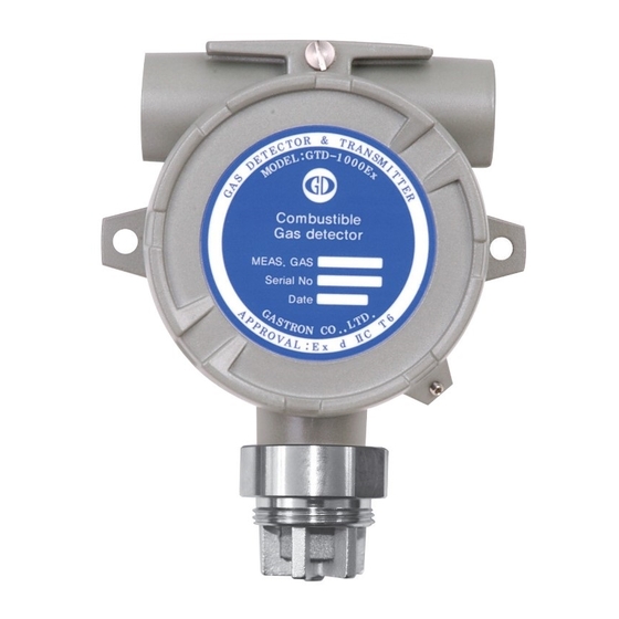
Basic Interface Analog 4-20mA current interface Option Rain Cover Body of GTD-1000Ex is made of Aluminum alloy and the gas sensor module is made of stainless steel. It consists of Transmitter 2Year Warranty a complete explosion-proof enclosure (Ex d IIC T6). This product can be installed in areas with potential combustible... -
Page 5: Electrical Specifications (Standard Type)
Analog 2500m (Cable Connection Length) EMC Protection: Complies with EN50270 [Figure 2. GTD-1000Ex Components] NAME DESCRIPTIONS Detector housing body Protects PCB Board built in Sensor and Housing from external environmental change and shock. It is assembled with detector housing body and protects PCB Board built in Sensor and Housing from 3.4. -
Page 6: Installation
It is a set screw that prevents cover opening from the detector housing body. 5.1. Detachment of Housing Cover [Table 1. GTD-1000Ex Components Description] ■ Turn the slotted set screw (M4 x 1ea) fixing the cover part of main body 3~4 tuns counter clockwise (ccw) using a hex wrench (M2) then turn the cover of gas leak detector ccw to detach the cover. -
Page 7: Main Pcb Configuration
GTD-1000Ex 5. Installation 5. Installation www.gastron.com Instruction Manual 12_13 5.2. Main PCB Configuration 5.3. Power and Signal Terminal Configuration ■ After detaching the cover, the Main PCB terminal layout appears as shown in the figure below. ■ After disassembling display parts, there is a terminal block in the Main PCB as shown in the figure below. Holding it with hands and pulling towards ceiling detaches it from the Main PCB. ■ Loosen 5 terminal fixing screws located at top part of detached terminal block CN8 (VIS, +, mA, -, ETH) Connector by turning counter-clockwise using a Θ driver. Connect DC 18~24 V power to +, and - then connect signal cable to mA. Tighten 5 terminal fixing screws clockwise so that terminal does not leave the track then insert Main PCB as the same condition before disassembly. -
Page 8: Method To Connect To External Control Unit
■ Max. Installation Length = VMAXDROP ÷ IMAX ÷ WIRER/m ÷ 2 ·VMAXDROP: Maximum Power Loop Voltage Drop (=Power Supply voltage - min operating voltage) ·IMAX : Max. Current of GTD-1000Ex ·WIRER/m: The resistance of the wire (ohms/meter value available in wire manufacturer's specification data sheet) ■ Example of installation lengths using 24 V power supply and 16 AWG is as follows. ·GTD-1000Ex minimum operating voltage = 18 Vdc ·VMAXDROP = 24 - 18 = 6V ·IMAX = 0.2A( 200mA ) ·6 ÷ 0.2 ÷ 0.01318 ÷ 2 = 1138.088m ≒ 1138m [Figure 6. External Control Unit Connection Method] [Figure 7. Calculation of GTD-1000Ex Installation Cable Length] ■ Power cable installation for each cable type is as shown in the table below. COPPER RESISTANCE(ohms/m) METERS 3.31 0.00521 2879 2.08 0.00828 1811 1.31 0.01318 1138 0.82... -
Page 9: Calibration And Maintenance
GTD-1000Ex 6. Calibration and Maintenance 6. Calibration and Maintenance www.gastron.com Instruction Manual 16_17 ■ S tabilization time of 30 min from the initial supply of operation power to the sensor for the stabilization of the sensor. 6.3. 4mA Adjustment (ZERO Calibration) Calibration and test must be performed approx. 30 min after when the sensor has been stabilized. ■ Check voltage of 18~31 V DC at both (+24 V) and (GND) of terminal block 'N5'. ■ Check whether (mA) terminal of terminal block 'CN5' is connected to the receiver. 6.1. 4-20mA Output Diagnosis ■ Change DMM to current measuring mode, then connect (+) and (-) terminals or DMM to TP5 (+mA) and TP6(-mA) -
Page 10: Span Calibration
GTD-1000Ex 6. Calibration and Maintenance 6. Calibration and Maintenance www.gastron.com Instruction Manual 18_19 6.4. SPAN Calibration 6.5. Gas Detector Calibration Method using Methane(CH4) Standard Gas ■ Check voltage of 18~31 V DC at both (+24 V) and (GND) of terminal block ‘CN5’. ■ Combustible gas sensor used for device can measure various types of combustible gas. However, each combustible ■ Check whether (mA) terminal of terminal block ‘CN5’ is connected to the receiver. gas has different properties including explosion range, heat generation rate, specific gravity, etc., therefore, it is ■ Change DMM to current measuring mode, then connect (+) and (-) terminals or DMM to TP5 (+mA) and... -
Page 11: Drawings And Dimensions
Avoid areas with vibration or shock since they can affect output values. Sensor part must be installed towards the direction of gravity. ■ This equipment has explosion-proof construction for internal pressure and belongs to GROUP II for gas and vapor in general work sites and chemical plants. It can be used in ZONE 1 (ONE) and ZONE 2 (TWO) hazardous sites. ■ Allowable temperature is 85 C or below, which corresponds to T6. [Figure 12. GTD-1000Ex Drawing]... - Page 12 GTD-1000Ex 8. Precautions before Installation 9. Revision History www.gastron.com Instruction Manual 22_23 ■ Use with surrounding temperature in a range of -20 C ~ 50 C. VERSION CONTENTS DATE ■ Installation Height: 1,000 M below sea level * Manual Initial Revision 2013.06.10 ■ Relative Humidity: 5% ~ 99% * Drawing and Function Added. 2015.06.29 * Changed Font 2016.05.19 ■ Installation Site: Indoor and Outdoor * Separated Factory mode manual 2016.09.27 ■ Explosion Ignition Grade for the Gas or Vapor: Ex d IIC T6...
Need help?
Do you have a question about the GTD-1000Ex and is the answer not in the manual?
Questions and answers