Table of Contents
Advertisement
Quick Links
GTD-5000F
Instruction Manual
Headquarters / Engineering research laboratory :
23 Gunpo Advance d Industry 1-ro(Bugok-dong), Gunpo-si, Gyeonggi-do
Tel +82-31-490-0800 Fax +82-31-490-0801
Yeongnam business office / Plant :
55 Gonghangap-gil 85beon-gil, Gangseogu, Busan Metropolitan City
Tel +51-973-8518 Fax +51-973-8519
E-mail : info@gastron.com
www.gastron.com
Read in detail for correct use.
Advertisement
Table of Contents

Related Manuals for GASTRON GTD-5000F


Summary of Contents for GASTRON GTD-5000F
- Page 1 Headquarters / Engineering research laboratory : 23 Gunpo Advance d Industry 1-ro(Bugok-dong), Gunpo-si, Gyeonggi-do Tel +82-31-490-0800 Fax +82-31-490-0801 Yeongnam business office / Plant : 55 Gonghangap-gil 85beon-gil, Gangseogu, Busan Metropolitan City Tel +51-973-8518 Fax +51-973-8519 E-mail : info@gastron.com www.gastron.com Read in detail for correct use.
- Page 2 Gas detectors satisfying customers. From now on, solve all anguishes concerning Gas detector with the products of Gastron Co. Ltd, We Gastron Co. will take a responsibility and give you satisfaction. In the present instruction manual, operation method for Gas detector as well as simple methods for maintenance and repair, etc.
-
Page 3: Table Of Contents
· · · · · · · · · · · · · · · · · · · · · · · · · · · · · · · · · · · · · · · · · · · · · · · · · · · · · · 10.1. GTD-5000F Cartridge Type Drawing and Dimensions ·... -
Page 4: Overview
Instruction Manual 06_07 3.1. Basic Specifications GTD-5000F gas detector has been developed to detect gas leaked from industrial sites and various gases generated from factories, gas storages, and manufacturing processes that produce or use flammable gases with vacuum construction and ITEMS SPECIFICATION to prevent accidents in advance. -
Page 5: Electrical Specifications (Standard Type)
GTD-5000F 3. Specification 3. Specification www.gastron.com Instruction Manual 08_09 3.3. Electrical Specifications (Standard Type) 3.4. Environmental Specifications ITEMS SPECIFICATION ITEMS SPECIFICATION Input Voltage(Standard) Absolute min: Transmitter -40 to 60 ℃ Operation Temperature ※ Customer supplied PSU must meet Nominal: Sensor... -
Page 6: Name And Description Of Each Part
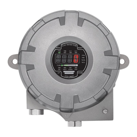
2 sec longer in measuring mode, it enters test mode (EMS: Emergency Maintenance System). Down key [Figure 2. GTD-5000F Cartridge Type] The icon lights on then it flashes. In stand-by mode, pressing down key for 2 sec or longer releases it. -
Page 7: Front Display Configuration
GTD-5000F 4. Name and Description of Each Part 5. Installation www.gastron.com Instruction Manual 12_13 4.2. Front Display Configuration 5.1. Terminal Configuration ■ <Warning - Do not open when electrical current is flowing> ■ Loosen case cover set screw located in the front part of the detector and detach the case cover. Loosen the two main sampling pump assembly set screws and pull to detach. - Page 8 GTD-5000F 5. Installation 5. Installation www.gastron.com Instruction Manual 14_15 5.2. Power and 4-20mA Signal Configuration 5.2.3. Power and 4~20mA 3 Sink Configuration ■ <Warning - Turn off power before connecting power terminal> ■ Connect (+) and (-) terminals for 4-20 mA sink output ■...
- Page 9 RS485B 'TRXD- or 'B' or 'N' Note1) Use cable designated for RS-485 Note 2) When there is no RS485 option available for GTD-5000F, the following function does not run. [Figure 8. GTD-5000F Installation Cable Length Calculation] 5.5. Installation Cable Length ■...
- Page 10 GTD-5000F 6. Operation 6. Operation www.gastron.com Instruction Manual 18_19 6.1. Power On 6.2. Measuring Mode ■ After checking wiring and power voltage, turn on the power switch located at the front part. - It displays gas concentration received from sensor cartridge on LCD digital display in numbers and the ■...
- Page 11 GTD-5000F 7. System Mode 7. System Mode www.gastron.com Instruction Manual 20_21 7.1. Mode Configuration LEVEL1 LEVEL2 LEVEL3 DEFAULT ZERO NO, YES ■ This device consists of the following menu configuration. Current Zero Measurement TYPE Menu Display Description Notes WAIT(Wait) CONFIGURATION MODE...
- Page 12 GTD-5000F 7. System Mode 7. System Mode www.gastron.com Instruction Manual 22_23 7.3. Configuration Mode - It is a mode that sets sensor calibration frequency in a unit of month. Pressing UP key or DOWN key increases or decrease number, respectively.
-
Page 13: Zero Calibration
GTD-5000F 7. System Mode 7. System Mode www.gastron.com Instruction Manual 24_25 7.4. Program Setting 7.5. Zero Calibration - When "FUNC" key is pressed for 2 sec or longer in gas concentration display mode at the same time, - When "FUNC" key is pressed for 2 sec or longer in gas concentration display mode at the same time, it enters menu selection mode. -
Page 14: Span Calibration
GTD-5000F 7. System Mode 7. System Mode www.gastron.com Instruction Manual 26_27 7.6. Span Calibration 7.7. Alarm Data Setting (Alarm Mode) - - When "FUNC" key is pressed for 2 sec or longer in gas concentration display mode at the same time, - When "FUNC"... - Page 15 GTD-5000F 7. System Mode 7. System Mode www.gastron.com Instruction Manual 28_29 - It is a mode that sets Dead band value for Alarm1 operation. Use " "UP key or DOWN key to set a value. - It is a mode that sets Dead band value for Alarm1 operation. Use UP key or DOWN key to set a value.
-
Page 16: Troubleshooting
GTD-5000F 8. Troubleshooting 8. Troubleshooting www.gastron.com Instruction Manual 30_31 8.1. Fault List 8.2. Warning List FAULT DESCRIPTION & CONDITION CAUSE WARNING DESCRIPTION & CONDITION CAUSE Occurs when internal IR detector channel is below active voltage 1) Waveguide of IR sensor cartridge W-01 When calibration validation has passed. -
Page 17: Interface Configuration
GTD-5000F 9. Interface Configuration 9. Interface Configuration www.gastron.com Instruction Manual 32_33 9.1. MODBUS RS485 9.2. MODBUS/TCP Interface 9.1.1. Interface setting 9.2.1. Interface setting ■ Data Format: RTU ■ Stop bit: 1bits ■ MODBUS Port Number 502 ■ Baud rate: 9600 bps ■... - Page 18 GTD-5000F 9. Interface Configuration 9. Interface Configuration www.gastron.com Instruction Manual 34_35 TYPE ADDRESS BITS DESCRIPTION TYPE ADDRESS BITS DESCRIPTION Decimal point indicator(0~3) 40020 BIT0~15 High Scale Value in floating point format word 1 of 2 Real type high scale setting...
-
Page 19: Drawings And Dimensions
10. Drawings and Dimensions 10. Drawings and Dimensions www.gastron.com Instruction Manual 36_37 10.1. GTD-5000F Cartridge Type Drawing and Dimensions 10.2. GTD-5000F IR Type Drawing and Dimensions [Figure 9. GTD-5000F Cartridge Type Drawing and Dimensions] [Figure 10. GTD-5000F] Type Drawing and Dimensions]... -
Page 20: Precautions Before Installation
GTD-5000F 11. Precautions before Installation 11. Precautions before Installation www.gastron.com Instruction Manual 38_39 11.1. Selecting a Place for Installation (Occupational Health & Safety Act Data) ■ Installation Height: 1,000 M below sea level ■ Relative Humidity: 5% ~ 99% (Non-condensing) A gas leak detector alarm shall be installed in the following places. -
Page 21: Revision History
GTD-5000F 12. Revision History www.gastron.com Instruction Manual 40_41 VERSION CONTENTS DATE Rev. 0 Initial Revision of Manual 2013.03.28 Rev. 1 Individual production of Cartridge/IR type manual 2013.10.22 Rev. 2 Corrected drawings in the manual 2013.12.11 Rev. 3 Corrected Typo 2014.03.17 Corrected version information Rev.
Need help?
Do you have a question about the GTD-5000F and is the answer not in the manual?
Questions and answers