Table of Contents
Advertisement
Quick Links
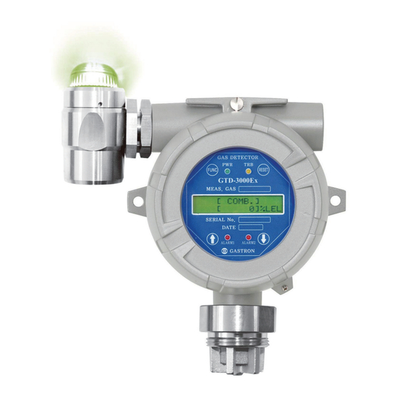
GTD-3000ExW
Instruction Manual
Headquarters / Engineering research laboratory :
23 Gunpo Advance d Industry 1-ro(Bugok-dong), Gunpo-si, Gyeonggi-do
Tel +82-31-490-0800 Fax +82-31-490-0801
Yeongnam business office / Plant :
55 Gonghangap-gil, 85beon-gil, Gangseogu, Busan Metropolitan City
Tel +51-973-8518 Fax +51-973-8519
E-mail : info@gastron.com
www.gastron.com
올바른 사용을 위해 자세히 읽어 주세요.
Advertisement
Table of Contents

Subscribe to Our Youtube Channel
Related Manuals for GASTRON GTD-3000ExW


Summary of Contents for GASTRON GTD-3000ExW
- Page 1 Headquarters / Engineering research laboratory : 23 Gunpo Advance d Industry 1-ro(Bugok-dong), Gunpo-si, Gyeonggi-do Tel +82-31-490-0800 Fax +82-31-490-0801 Yeongnam business office / Plant : 55 Gonghangap-gil, 85beon-gil, Gangseogu, Busan Metropolitan City Tel +51-973-8518 Fax +51-973-8519 E-mail : info@gastron.com www.gastron.com 올바른 사용을 위해 자세히 읽어 주세요.
- Page 2 Gas detectors satisfying customers. From now on, solve all anguishes concerning Gas detector with the products of Gastron Co. Ltd, We Gastron Co. will take a responsibility and give you satisfaction.
-
Page 3: Table Of Contents
GTD-3000ExW Contents Contents www.gastron.com Instruction Manual 04_05 1. Overview ······································································································································································ 7. System Mode ······························································································································································ 7.1. PROGRAM MODE ············································································································································· 2. Configuration ······························································································································································ 7.2. CALIBRATION MODE ········································································································································· 7.2.1. Zero Calibration ······································································································································· 3. Specification ······························································································································································· 7.2.2. Span Calibration ······································································································································ 3.1. Basic Specifications ···········································································································································... -
Page 4: Overview
Response Time 90% of full Scale in less than 15 sec Body of GTD-3000ExW is made of Aluminum alloy and the gas sensor module is made of stainless steel. It consists of a Approvals Classification KCs: Ex d llC T6,T5,T4 complete explosion-proof enclosure (Ex d IIC T6). -
Page 5: Electrical Specifications (Standard Type)
STP(Shielded Twisted Pair) Analog 2500m Cable Connection Length RS485 1000m EMC Protection: Complies with EN50270 [Figure 2. GTD-3000ExW Components] 3.4. Environmental Specifications NAME DESCRIPTIONS ITEMS SPECIFICATION Housing Protects Sensor and PCB Board built in the Housing from external environmental change and shock. -
Page 6: Lamp Function Description
(Each touch returns to the previous status by one unit. During conversion of mode or number, use the Magnet-Bar and touch once. Each touch converts [Table 1. GTD-3000ExW Transmitter Components Description] ↑(Up) key or changes one level. (Converts to the next level) During conversion of mode or number, use the Magnet-Bar and touch once. -
Page 7: Installation
GTD-3000ExW 5. Installation 5. Installation www.gastron.com Instruction Manual 12_13 It is prohibited for an individual, other than an approved user or a technician responsible for installation and repair from 5.2. Main PCB Configuration the head office, to install a gas leak detector on site or open the cover of the installed gas leak detector and manipulate ■... -
Page 8: Wiring For 4~20Ma Sink Operation Type
[Table 3. CN8 Terminal Detailed Description] ■ Use CVVS or CVVSB 2.0sq↑ Shield Cable for terminal configuration. ■ To connect 4 Pin terminal from the existing old GTD-3000ExW model, connect terminals in reference to pin #2, which is +24V. [Figure 8. 4-20mA Sink Configuration]... -
Page 9: Relay And Network Terminal Configuration
GTD-3000ExW 5. Installation 5. Installation www.gastron.com Instruction Manual 16_17 5.4.2. Relay Mode Configuration 5.3.3. Wiring for 4~20mA 3Wire Sink Operation Type ■ Connect (+) and (-) terminals for 4-20 mA sink output at PLC side to VISO terminal and power (24V DC) (-) terminal, respectively. -
Page 10: Installation Cable Length
6.1. Initial Operation Status (Power On) ■ The maximum length between GTD-3000ExW and power supply is decided by wire specification. ■ After wiring to power terminal at the top of Main PCB board then supply power, the following contents are displayed on LCD. -
Page 11: Operation Flow
[SUCCESS / FAIL ] CALIBRATION DATA ALARM OPERATING [AUTO/MANUAL] AUTO ALARM RELAY TYPE DE-ENERGIZED/ENERGIZED DE-ENERGIZED [Figure 12. GTD-3000ExW Mode Configuration] FAULT RELAY TYPE DE-ENERGIZED/ENERGIZED DE-ENERGIZED ALARM1 TYPE SEL. ■ Operation keys for detector system mode are defined as below. [INCREASE/ DECREASE] INCREASE... -
Page 12: System Mode
GTD-3000ExW 6. Detector Operation Flow 7. System Mode www.gastron.com Instruction Manual 22_23 7.1. PROGRAM MODE LEVEL2 LEVEL1 DEFAULT NAME PARAMETER ALARM2 TYPE SEL. PASSWORD - Contacting "FUNC" key with the Magnet-bar for 2 sec or longer in Measuring Mode enters Password mode. -
Page 13: Calibration Mode
GTD-3000ExW 7. System Mode 7. System Mode www.gastron.com Instruction Manual 24_25 7.2. Calibration Mode 7.2.2. Span Calibration ■ Due to characteristics of the gas detector, minimum 30 min of stabilization time is required and maintenance - Contact "↑" or "↓" key to select "Calibration Mode". -
Page 14: Alarm Mode
GTD-3000ExW 7. System Mode 7. System Mode www.gastron.com Instruction Manual 26_27 7.3. ALARM MODE - It is a mode that sets whether to contact relay contact during Alarm1 operation. Contact "↑" or "↓" key ALARM1 RELAY CTL to change the display between "ON" or "OFF". -
Page 15: Troubleshooting
GTD-3000ExW 8. Troubleshooting 9. Interface Configuration www.gastron.com Instruction Manual 28_29 8.1. Fault List 9.1. MODBUS RS485 9.1.1. Interface setting FAULT MESSAGE DESCRIPTION & CONDITION CAUSE [FAULT-01] ■ Data Format: RTU Occurs when sensor module is disconnected. Defective Sensor Module connection "SENOR EMPTY"... -
Page 16: Drawings And Dimensions
GTD-3000ExW 10. Drawings and Dimensions 10. Drawings and Dimensions www.gastron.com Instruction Manual 30_31 10.1. Standard Type 10.2. Warning Light GTL-100 [Figure 13. GTD-3000ExW Standard Type Drawing] [Figure 14. GTL-100 Drawing]... -
Page 17: Precautions Before Installation
■ Allowable temperature is 85 C or below, which corresponds to T6. ■ Surrounding temperature shall be in a range of -20 to 60 °C (For the main unit and sensor, refer to each sensor manual.) [Figure 15. GTD-3000ExW 경광등 결합 외형도]... -
Page 18: Revision History
GTD-3000ExW 11. Precautions before Installation 12. Revision History www.gastron.com Instruction Manual 34_35 ■ Installation Height: 1,000 M below sea level VERSION CONTENTS DATE ■ Relative Humidity: 5% ~ 99% (Non-condensing) * Manual Initial Revision 2017. 09. 29 ■ Installation Site: Indoor and Outdoor * Correct typos and typographical errors 2019.
Need help?
Do you have a question about the GTD-3000ExW and is the answer not in the manual?
Questions and answers