Table of Contents
Advertisement
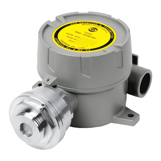
GTD-1000Tx(M)
Instruction Manual
Headquarters / Engineering research laboratory :
23 Gunpo Advance d Industry 1-ro(Bugok-dong), Gunpo-si, Gyeonggi-do
Tel +82-31-490-0800 Fax +82-31-490-0801
Yeongnam business office / Plant :
55 Gonghangap-gil 85beon-gil, Gangseogu, Busan Metropolitan City
Tel +51-973-8518 Fax +51-973-8519
E-mail : info@gastron.com
www.gastron.com
Read in detail for correct use.
Advertisement
Table of Contents

Related Manuals for GASTRON GTD-1000T Series


Summary of Contents for GASTRON GTD-1000T Series
- Page 1 Headquarters / Engineering research laboratory : 23 Gunpo Advance d Industry 1-ro(Bugok-dong), Gunpo-si, Gyeonggi-do Tel +82-31-490-0800 Fax +82-31-490-0801 Yeongnam business office / Plant : 55 Gonghangap-gil 85beon-gil, Gangseogu, Busan Metropolitan City Tel +51-973-8518 Fax +51-973-8519 E-mail : info@gastron.com www.gastron.com Read in detail for correct use.
- Page 2 Gas detectors satisfying customers. From now on, solve all anguishes concerning Gas detector with the products of Gastron Co. Ltd, We Gastron Co. will take a responsibility and give you satisfaction.
-
Page 3: Table Of Contents
GTD-1000Tx(M) Contents Contents www.gastron.com Instruction Manual 04_05 1. Overview ······································································································································································ 7.2.1. Zero Calibration ······································································································································· 7.2.2. Span Calibration ······································································································································ 2. Configuration ······························································································································································ 7.3. ALARM Mode ···················································································································································· 7.4. Device Mode ······················································································································································ 3. Specification ································································································································································ 8. Troubleshooting 3.1. Basic Specifications ············································································································································ ·························································································································································· 3.2. -
Page 4: Overview
GTD-1000Tx(M) 1. Overview 3. Specification www.gastron.com Instruction Manual 06_07 GTD-1000Tx(M) toxic gas detector has been developed to detect gas leaked from industrial sites and various toxic gases 3.1. Basic Specifications generated from factories, gas storages, and manufacturing processes that produce or use toxic gases and to prevent... -
Page 5: Electrical Specifications (Standard Type)
GTD-1000Tx(M) 3. Specification 4. Name and Description of Each Part www.gastron.com Instruction Manual 08_09 3.3. Electrical Specifications (Standard Type) 4.1. Components ITEMS SPECIFICATION Input Voltage(Standard) Absolute min: ※ Customer supplied PSU must meet Nominal: requirements IEC1010-1 and CE Absolute max: Marking requirements. Ripple maximum allowed: 1V pk-pk Max. -
Page 6: Installation
GTD-1000Tx(M) 4. Name and Description of Each Part 5. Installation www.gastron.com Instruction Manual 10_11 ■ It is prohibited for an individual, other than an approved user or a technician responsible for installation and repair ITEMS SPECIFICATION CN6 consists of DC 24 V power supply and DC 4~20 mA standard output connection terminal from the head office, to install a gas leak sensor on site or open the cover of the installed gas leak sensor and Power/Signal Terminal (VISO, +24V, mA, GND, ETH). -
Page 7: Main Pcb Configuration
GTD-1000Tx(M) 5. Installation 5. Installation www.gastron.com Instruction Manual 12_13 5.2. Main PCB Configuration 5.3. Terminal Configuration ■ After detaching the display parts, the Main PCB terminal layout appears as shown in the figure below. ■ <Warning - Turn off power before connecting power terminal> ■ Loosen 5 terminal fixing screws located at top part of detached terminal block CN6 (VIS, +, mA, -, ETH) Connector by turning counter-clockwise using a Θ driver. Connect DC 18~24 V power to +, and - then connect signal cable to mA. Tighten 5 terminal fixing screws clockwise (cw) so that terminal does not leave the track then insert Main PCB as the same condition before disassembly. -
Page 8: Wiring For 4~20Ma Source Operation Type
GTD-1000Tx(M) 5. Installation 5. Installation www.gastron.com Instruction Manual 14_15 5.3.1. Wiring for 4~20mA Source Operation Type 5.3.3. Wiring for 4~20mA 3Wire Sink Operation Type ■ Connect 4-20 mA signal terminal at PLC side to 'mA' ■ Connect (+) and (-) terminals for 4-20 mA sink output of GTD-1000Tx(M). GND terminal is used in common at PLC side to VISO terminal and power (24V DC) with power. -
Page 9: Detector Operation Flow
GTD-1000Tx(M) 5. Installation 6. Detector Operation Flow www.gastron.com Instruction Manual 16_17 Display board is connected and used during maintenance and repair. For normal display operation after connecting in operation status, contact ‘RESET’ key. 6.1. Initial Operation Status (Power On) ■ After wiring to power terminal at the top of Main PCB board then supply power, the following contents are displayed on LCD. -
Page 10: Operation Flow
GTD-1000Tx(M) 6. Detector Operation Flow 6. Detector Operation Flow www.gastron.com Instruction Manual 18_19 6.3. Operation Flow 6.4. Menu Configuration Table ■ A fter power on, it passes self-diagnostic process then enters Measuring Mode. Here, by operating front keys, LEVEL2 LEVEL1 DEFAULT NAME PARAMETER you can go to internal System Mode. GAS TYPE (Gas Type) [DEFIN./USER] DEFIN. -
Page 11: System Mode
GTD-1000Tx(M) 7. System Mode 7. System Mode www.gastron.com Instruction Manual 20_21 7.1. PROGRAM MODE 7.2. Calibration Mode ■ Due to characteristics of the gas detector, minimum 30 min of stabilization time is required and maintenance PASSWORD - Contacting "FUNC" key for 2 sec or longer in Measuring Mode enters Password mode. condition may change depending on site condition.. [**] - After setting Password using "↑" or "↓" key, contact “FUNC" key. - If password is correct, it enters Program mode. PROGRAM 7.2.1. Zero Calibration - By contacting "↑" or "↓" key, mode changes in defined order. -
Page 12: Span Calibration
GTD-1000Tx(M) 7. System Mode 7. System Mode www.gastron.com Instruction Manual 22_23 7.2.2. Span Calibration 7.3. ALARM MODE CALIBRA. - Contact "↑" or "↓" key to select "Calibration Mode". PASSWORD - Contacting “FUNC” key for 2 sec or longer in Measuring Mode enters Password mode. MODE - Contact "FUNC" key when "CALIBRA. MODE" is displayed to enter Calibration Mode. [**] - After setting Password using "↑" or "↓" key, contact "FUNC" key. - Contact "↑" or "↓" key to select "Alarm Mode". CALIBRA. ALARM - Contact "↑" or "↓" key to achieve [SPAN] then contact "FUNC" key to enter Span Calibration mode. - Contact "FUNC" key when "ALARM MODE" is displayed to enter Alarm setting mode. [SPAN] MODE - Contact "RESET" key to return to Measuring Mode. - It is a setting where Alarm Mode Setting is turned on or off. -
Page 13: Device Mode
GTD-1000Tx(M) 7. System Mode 8. Troubleshooting www.gastron.com Instruction Manual 24_25 8.1. Fault List - It is a mode that sets operational direction of Alarm2. Contact "↑" or "↓" key to display "INC" or A2 TYPE [INC] "DEC". FAULT MESSAGE DESCRIPTION & CONDITION CAUSE - "INC" mode operates when the value is equal or larger than set alarm threshold. "DEC" mode A2 TYPE FAULT2 operates when the value is equal or less than set alarm threshold. -
Page 14: Interface Configuration
GTD-1000Tx(M) 9. Interface Configuration 10. Drawings and Dimensions www.gastron.com Instruction Manual 26_27 9.1. MODBUS RS485 10.1. Standard Type 9.1.1. Interface setting ■ Data Format: RTU ■ Baud rate: 9600 bps ■ Data bits: 8bits ■ Stop bit: 1bits ■ Parity: Even ■ For details, please go to www. modbus.org 9.1.2. MODBUS RS485 Register map TYPE ADDRESS BITS DESCRIPTION Measured Gas 30001 BIT15~0... -
Page 15: Precautions Before Installation
GTD-1000Tx(M) 11. Precautions before Installation 11. Precautions before Installation www.gastron.com Instruction Manual 28_29 11.1. Selecting a Place for Installation (Occupational Health & Safety Act Data) ■ Installation Height: 1,000 M below sea level ■ Relative Humidity: 5% ~ 99% (Non-condensing) A gas leak detector alarm shall be installed in the following places. ■ Installation Site: Indoor and Outdoor ■ Around chemical equipment and accessories that have concerns of gas leak. -
Page 16: Revision History
GTD-1000Tx(M) 12. Revision History www.gastron.com Instruction Manual 30_31 VERSION CONTENTS DATE * Manual Initial Revision 2017.11.17 Changed Address 2018.01.04...
Need help?
Do you have a question about the GTD-1000T Series and is the answer not in the manual?
Questions and answers