Table of Contents
Advertisement
Quick Links
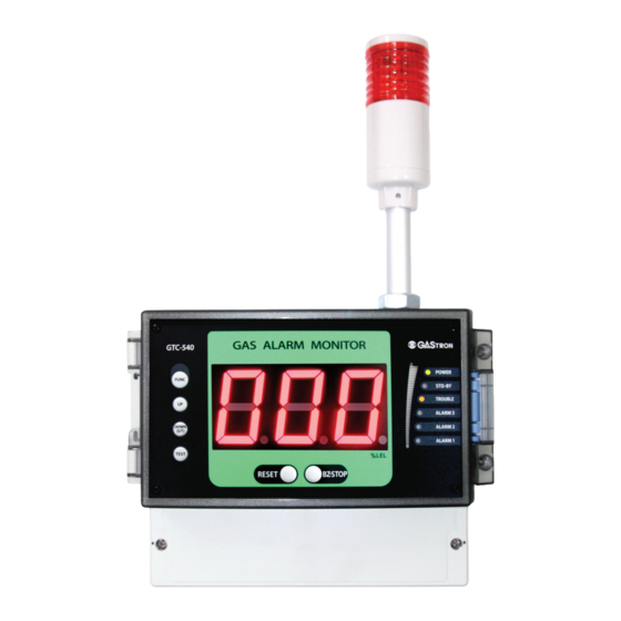
GTC-540
Instruction Manual
Headquarters / Engineering research laboratory :
23 Gunpo Advance d Industry 1-ro(Bugok-dong), Gunpo-si, Gyeonggi-do
Tel +82-31-490-0800 Fax +82-31-490-0801
Yeongnam business office / Plant :
55 Gonghangap-gil 85beon-gil, Gangseogu, Busan Metropolitan City
Tel +51-973-8518 Fax +51-973-8519
E-mail : info@gastron.com
www.gastron.com
Read in detail for correct use.
Advertisement
Table of Contents

Subscribe to Our Youtube Channel
Related Manuals for GASTRON GTC-500 Series


Summary of Contents for GASTRON GTC-500 Series
- Page 1 Headquarters / Engineering research laboratory : 23 Gunpo Advance d Industry 1-ro(Bugok-dong), Gunpo-si, Gyeonggi-do Tel +82-31-490-0800 Fax +82-31-490-0801 Yeongnam business office / Plant : 55 Gonghangap-gil 85beon-gil, Gangseogu, Busan Metropolitan City Tel +51-973-8518 Fax +51-973-8519 E-mail : info@gastron.com www.gastron.com Read in detail for correct use.
- Page 2 Gas & Flame We sincerely thank you for purchasing the product of Gastron Co. Ltd. Our Gastron Co.Ltd. is a company specialized in Gas Detector & Gas Monitoring System and have been Detection System recognized by many customers for the best quality and use convenience. We always seek to help our customers to find the product they need and we continuously research to develop gas detectors that satisfies our customers.
-
Page 3: Table Of Contents
GTC-540 Contents Contents www.gastron.com Instruction Manual 04_05 1. Overview ······································································································································································ 6.4.9. Calibration Data Initialization Mode ······································································································· 2. Characteristics 7. Interface Configuration ····························································································································································· ············································································································································· 7.1. MODBUS RS485 ····················································································································································· 3. Specifications ······························································································································································· 7.1.1. Interface Setting ······································································································································ 3.1. Basic Specifications ············································································································································ 7.1.2. MODBUS RS485 Register map ···············································································································... -
Page 4: Overview
GTC-540 1. Overview 3. Specifications www.gastron.com Instruction Manual 06_07 Receiver of GTC-540 is a receiver with high-performance A/D converter and micro-processor and has various functions 3.1. Basic Specifications built-in. The receiver is a stand-alone type that connects to a detector and is protected by a case made of ABS material. It... -
Page 5: Electrical Specifications (Standard Type)
GTC-540 3. Specifications 4. Name and Description of Each Part www.gastron.com Instruction Manual 08_09 3.3. Electrical Specifications (Standard Type) ITEMS SPECIFICATION Absolute min: AC 90V Input Voltage(AC Type/Standard) Nominal: AC 220V Absolute max: AC 250V Absolute min: Input Voltage(DC Type) Nominal: ※ Customer supplied PSU must meet requirements... - Page 6 GTC-540 4. Name and Description of Each Part 4. Name and Description of Each Part www.gastron.com Instruction Manual 10_11 ITEMS SPECIFICATION ITEMS SPECIFICATION It is made of ABS Material. It fixes the display and protects the circuit from surrounding "BZ-STOP" S/W...
-
Page 7: Installation
GTC-540 5. Installation 5. Installation www.gastron.com Instruction Manual 12_13 ■ It is prohibited for an individual, other than an approved user or a technician responsible for installation and repair 5.2. Signal Terminal Configuration from the head office, to install a gas detector on site or open the cover of the installed gas leak detector and manipulate it. This may cause serious loss of life and property from fire, explosion, and etc. In addition, please check whether there is any remaining explosive gas or combustible material in the surroundings. -
Page 8: Relay Terminal Configuration
GTC-540 5. Installation 5. Installation www.gastron.com Instruction Manual 14_15 5.3. Relay Terminal Configuration 5.4. 3-wire Type Gas detector Connection Method ■ Using CN5 terminal, it consists of 3 SPDT-type Alarm relay and 1 SPDT-type Trouble relay. ■ When the gas detector has 3-wire (V+, mA, V-) for power and ■ Alarm Lamp (LP) can connect DC external warning light. 420 mA output components, connect to the Channel Unit as ■ LP terminal output DC +24V power regardless of AC, DC power mode. This is to use an external DC flash light or shown in Figure 5. external devices. -
Page 9: Operation Method
GTC-540 6. Operation Method 6. Operation Method www.gastron.com Instruction Manual 16_17 6.1. Power ON 6.2. Test Mode ■ Check wirings for operation power, detection parts, alarm parts, and concentration display. ■ Pressing "TEST" S/W for 2 sec or longer in gas concentration display mode enters Test mode. ■ Check the power input then turn ON the power S/W. ■ In test mode, when it passes 30 min after the last S/W control, it automatically returns to the gas concentration ■ Check whether power LED at alarm and concentration display parts light on. display mode. ■ Check whether "SELF" is displayed on FND concentration display part. - When it enters Test mode, gas concentration number displays and flickers. - This function enables testing at channel unit without injecting gas to the detector sensor. It can set an arbitrary concentration when the user presses "Test" S/W and alarm function operates... -
Page 10: Operation Setting
GTC-540 6. Operation Method 6. Operation Method www.gastron.com Instruction Manual 18_19 6.4. Operation Setting LEVEL4 LEVEL1 LEVEL2 LEVEL3 DEFAULT (Range available for Selection) 6.4.1. Setting Table FUNC→ FUNC→ FUNC → FUNC → NEXT (Maintenance-Level) 0 ~ Full range LEVEL4 LEVEL1... -
Page 11: Program Mode
GTC-540 6. Operation Method 6. Operation Method www.gastron.com Instruction Manual 20_21 6.4.2. PROGRAM MODE ■ After setting a password, move to "UP" S/W or "DOWN" S/W then press "FUNC" S/W to enter the mode. ■ In Program setting function, when it passes 10 s after the last S/W control, it automatically returns to gas - Decimal point is used when it is necessary to change decimal point for measured range. concentration display mode. Decimal point position is set by pressing "UP" S/W or"DOWN" S/W where it changes as shown on the left. (Default 100) Ex)100, 10.0, 1.00... -
Page 12: Alarm Mode
GTC-540 6. Operation Method 6. Operation Method www.gastron.com Instruction Manual 22_23 - A message indicating completion of setting is displayed as "End" for 2 sec then it returns to gas - Function to set SAD value. SAD value increase or decreases when "UP" S/W or "DOWN" S/W is concentration display status. pressed, respectively. For negative value, "-" sign displays above the first digit. (Default 0) - When a desired SAD is displayed, press "FUNC" S/W to set it and enter the next item. ▼ ▲ - When "FUNC" S/W is pressed, it enters Program Mode. - (Ex.) When output error at detector is -2, the actual display should be -2, but SAD set value of 2 is corrected and 0 is displayed. - Page 13 GTC-540 6. Operation Method 6. Operation Method www.gastron.com Instruction Manual 24_25 - Alarm level is set to the concentration outlined in domestic regulations as factory setting. - ON/OFF of Energizer Mode is determined by "UP" S/W or "DOWN" S/W. - It is a mode to set a direction of Alarm 1 operation. Pressing "UP" S/W or "DOWN" S/W displays - When ON, it is in Normal Open (NO) status. "H" or "L", respectively. - When OFF, it is in Normal Close (NC) status.
-
Page 14: Option Mode (Option Setting)
■ In Option setting mode, when it passes 10 sec after the last S/W control, it automatically returns to gas - When "RESET" S/W is pressed, it returns to Alarm Setting Mode. concentration display mode. ■ In option mode, most settings are factory preset, therefore, this function should not be adjusted. - It is a mode to change Alarm1 contact output and "ON" and "OFF" mode changes when "UP" S/W When it is unavoidable, the user must seek help from GasTron to adjust. or "DOWN" S/W are pressed. - Alarm1 contact output mode has two modes; "ON" and "OFF". In OFF mode, Alarm 1 contact - It is a mode to set Option function. output does not run. In ON mode, it runs. -
Page 15: Test Mode
GTC-540 6. Operation Method 6. Operation Method www.gastron.com Instruction Manual 28_29 6.4.5. Test Mode - By pressing "UP" S/W or "DOWN" S/W, ON/OFF status can be set and when it is ON, UNDER function is available for use. (Default OFF) ■ After setting a password, move to "UP" S/W or "DOWN" S/W then press "FUNC" S/W to enter the mode. - When a desired item is displayed, press "FUNC" S/W to set it and enter the next item. ■ In test mode, when it passes 10 sec after the last S/W control, it automatically returns to gas concentration display mode. - When "RESET" S/W is pressed, it enters Option Setting Mode. - Test mode enables testing without injecting gas to the detector sensor. The user can set an - For measurement display, it displays raw data from -XXXX ~ +YYYY. -
Page 16: 485 Setting Mode
GTC-540 6. Operation Method 6. Operation Method www.gastron.com Instruction Manual 30_31 - It is mA Output Signal Test Mode. - Press "FUNC" S/W to enter mA Output setting function. - Channel number is a mode that enters serial number of control unit to enable recognition of - When "RESET" S/W is pressed, it enters Test Setting Mode. operation status of each control unit at other equipment, such as PC, etc. Pressing "UP" S/W or "DOWN" S/W increase or decreases Address No. Value, respectively. (Default 1) ▼ ▲... -
Page 17: Maintenance Mode
GTC-540 6. Operation Method 6. Operation Method www.gastron.com Instruction Manual 32_33 6.4.7. Maintenance Mode ■ Pressing both "RESET" and "TEST" S/W for 2 sec or longer in gas concentration display mode enters Maintenance mode. - It is a mode that displays value converted from processor after inputting 20mA current to (mA) ▼ ■ "RESET" S/W must be pressed in Maintenance mode to return to gas concentration display mode. terminal. - Press "FUNC" S/W when the displayed number is stable to display SUC (Success) for a current input within normal range and move to the next item. -
Page 18: Factory Initialization Mode
It is a mode that resets only calibration data from the currently saved data to the original factory ■ By pressing "FUNC" S/W + "UP" S/W + "DOWN" S/W for 2 seconds, , it enters the mode. setting. When "RESET" S/W is pressed, it returns to gas concentration display mode. ■ Factory initial is a mode that resets the data to the original factory setting. ■ In factory initialization mode, most settings are factory preset, therefore, this function should not be adjusted. When it is unavoidable, the user must seek help from GasTron to adjust. - Press "FUNC" S/W TO enter. It is a mode that resets the current saved data to the original factory setting. ▼ ▲ - By pressing "UP" S/W or "DOWN" S/W, Yes/no status can be set. When it is "Yes", Calibration When "RESET" S/W is pressed, it returns to gas concentration display mode. -
Page 19: Interface Configuration
GTC-540 7. Interface Configuration 8. Drawings and Dimensions www.gastron.com Instruction Manual 36_37 7.1. MODBUS RS485 8.1. Drawing 1 7.1.1. Interface setting ■ Data Format: RTU ■ Baud rate: 9600 bps ■ Data bits: 8bits ■ Stop bit: 1bits ■ Parity: Even ■ For details, please go to www. modbus.org 7.1.2. MODBUS RS485 Register map TYPE ADDRESS BITS DESCRIPTION Measured Gas 30001 BIT15~0... -
Page 20: Revision History
GTC-540 8. Drawings and Dimensions 9. Revision History www.gastron.com Instruction Manual 38_39 8.2. Drawing 2 VERSION CONTENTS DATE Initial Revision of Manual 2011. 08. 25 Changed Main PCB Layout and Added function 2014. 01. 15 Corrected Program Mode Function 2015. 04. 27 Changed Font 2016.
Need help?
Do you have a question about the GTC-500 Series and is the answer not in the manual?
Questions and answers