Table of Contents
Advertisement
Quick Links
Advertisement
Table of Contents

Related Manuals for GASTRON GTD-3000Ex


Summary of Contents for GASTRON GTD-3000Ex
- Page 1 GTD-3000Ex Instruction Manual Read in detail for correct use.
- Page 2 GTD-3000Ex Instruction Manual Gas & Flame Detection System When abnormalities occur after purchasing the product, please contact the following address. ·Address : 23 Gunpo Advanced Industry 1-ro, Gunpo-si, Gyeonggi-do ·Tel : 031-490-0800 ·Fax : 031-490-0801 ·URL : www.gastron.com ·e-mail : info@gastron.com...
- Page 3 Thank you very much for purchasing a product from Gastron Co. Ltd. Our Gastron Co.Ltd. is a company specialized in Gas Detector & Gas Monitoring System and have been recognized by many customers for the best quality and use convenience. We always seek to help our customers to find the product they need and we continuously research to develop gas detectors that satisfies our customers.
-
Page 4: Table Of Contents
GTD-3000Ex Contents Instruction Manual Overview · · · · · · · · · · · · · · · · · · · · · · · · · · · · · · · · · · · · · · · · · · · · · · · · · · · · · · · · · · · · · · · · · · · · · · · · · · · · · · · · · · · · · · · · · · ·... - Page 5 Contents www.gastron.com 04_05 7. System Mode · · · · · · · · · · · · · · · · · · · · · · · · · · · · · · · · · · · · · · · · · · · · · · · · · · · · · · · · · · · · · · · · · · · · · · · · · · · · · · · · · · · · · ·...
-
Page 6: Overview
2. Configuration Body of GTD-3000Ex is made of Aluminum alloy and the gas sensor module is made of stainless steel. It consists of a complete explosion-proof enclosure (Ex d IIC T6). This product can be installed in areas with flammable gas leak and explosion hazards. -
Page 7: Specification
3. Specification www.gastron.com 06_07 3.1. Basic Specifications ITEMS SPECIFICATION Measuring Type Diffusion Measuring Value Display Local Digital LCD or OLED Display - Catalytic Cell) Measuring Method - Thermal Conductivity Cell - Heated-semiconductor Cell Detectible Gas Flammable gas Measuring Range 0~100% LEL Accuracy ≤... -
Page 8: Electrical Specifications (Standard Type)
GTD-3000Ex 3. Specification Instruction Manual 3.3. Electrical Specifications (Standard Type) ITEMS SPECIFICATION Input Voltage(Standard) Absolute min: ※ Customer supplied PSU must meet Nominal: requirements IEC1010-1 and CE Absolute max: Marking requirements. Ripple maximum allowed: 1V pk-pk Max. wattage: 4.8W @+24 VDC Wattage Max. -
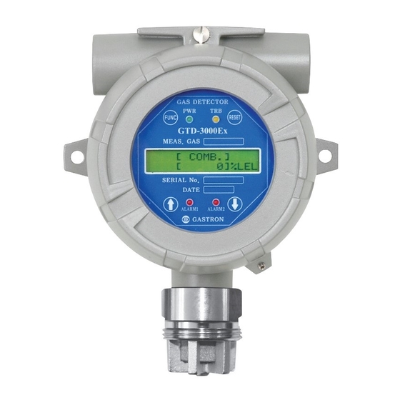
Page 9: Name And Description Of Each Part
4. Name and Description of Each Part www.gastron.com 08_09 4.1. Components [Figure 2. GTD-3000Ex Components] NAME DESCRIPTIONS Housing Protects Sensor and PCB Board built in from external environmental change and the Housing shock It amplifies output signal from the sensor and converts and send it as DC 4~20 mA standard output. - Page 10 Jumper to B operates in A contact mode. Warning Light It is a connector connected when a warning light is used. (Option) Connector Program It is a connector for downloading the program for the product. Connector [Table 1. GTD-3000Ex 구성요소 설명]...
-
Page 11: Installation
5. Installation www.gastron.com 10_11 It is prohibited for an individual, other than an approved user or a technician responsible for installation and repair from the head office, to install a gas leak detector on site or open the cover of the installed gas leak detector and manipulate it. -
Page 12: Main Pcb Configuration
GTD-3000Ex 5. Installation Instruction Manual 5.2. Main PCB Configuration ■ After detaching the display parts, the Main PCB terminal layout appears as shown in the figure below. [Figure 5. Main PCB Terminal Layout] NAME DESCRIPTION CN11 Power & Output Signal Terminal CN10 Alarm &... -
Page 13: Terminal Configuration
5. Installation www.gastron.com 12_13 5.3. Power and 4-20mA Terminal Configuration ■ <Warning - Turn off power before connecting power terminal> ■ After disassembling display parts, there is a terminal block in the Main PCB as shown in the figure below. -
Page 14: Wiring For 4~20Ma Source Operation Type
5.3.1. Wiring for 4~20mA Source Operation Type ■ Connect 4-20 mA signal terminal at PLC side to 'mA' of GTD-3000Ex. GND terminal is used in common with power. Then, turn on the J1 Jumper. ■ HART Communicator can only be used in models using HART Option board. -
Page 15: Wiring For 4~20Ma 3Wire Sink Operation Type
■ Connect (+) and (-) terminals for 4-20 mA sink output at PLC side to VISO terminal and power (24V DC) (-) terminal, respectively. Connect‘mA’terminal of GTD-3000Ex to‘GND’ terminal. Then, turn off the J1 Jumper. [Figure 9. 4-20mA 3Wire Sink Configuration] 5.4. -
Page 16: Relay Mode Configuration
5.4.2. Relay Mode Configuration [Figure 11. Relay Mode Setting] ■ Relay of GTD-3000Ex operates in 2 types of method; Normal open and Normal close. The Jumper is constructed to configure relay operation method at the Main PCB and operating setting is as follows. -
Page 17: Installation Cable Length
16_17 5.5. Installation Cable Length ■ The maximum length between GTD-3000Ex and power supply is decided by wire specification. ■ Max. Installation Length = VMAXDROP ÷ IMAX ÷ WIRER/m ÷ 2 ·VMAXDROP: Maximum Power Loop Voltage Drop (=Power Supply voltage - min operating voltage) ·IMAX : Max. -
Page 18: Detector Operation Flow
GTD-3000Ex 6. Detector Operation Flow Instruction Manual 6.1. Initial Operation Status (Power On) ■ After wiring to power terminal at the top of Main PCB board then supply power, the following contents are displayed on LCD. Approx. 30 m of stabilization of time is needed from the initial supply of operation power and it starts to operate normally after sufficient stabilization. -
Page 19: Operation Flow
■ When“RESET”key contacts at Program Mode Screen, it returns to Measuring Mode. When "RESET" key contacts at each Program Setting Screen, it returns to the parent step. [Figure 13. GTD-3000Ex Mode Configuration] ■ Operation keys for detector system mode are defined as below. -
Page 20: Menu Configuration Table
GTD-3000Ex 6. Detector Operation Flow Instruction Manual 6.4. Menu Configuration Table LEVEL2 LEVEL1 DEFAULT NAME PARAMETER GAS TYPE [DEFINE/USERG.] DEFINE GAS SELECT Factory Set COMB. UNIT SELECT %/%LEL/PPM/PPB %LEL PROGRAMMABLE MODE DECIMAL POINT 0.100/1.00/10.0/100 HIGH SCALE 1~9999 PASSWORD 00~99 ZERO CALIBRATION... - Page 21 6. Detector Operation Flow www.gastron.com 20_21 LEVEL2 LEVEL1 DEFAULT NAME PARAMETER ALARM2 TYPE SEL. [INCREASE/ DECREASE] INCREASE (ALARM2 TYPE SELECT) ALARM2 LEVEL ADJ [ 1~Full Scale] (ALARM2 LEVEL ADJUST) ALARM PROGRAM ALARM2 DEAD BAND [ 0.0~ 10% of Full Scale ]% FS...
-
Page 22: System Mode
GTD-3000Ex 7. System Mode Instruction Manual 7.1. PROGRAM MODE - Contacting "FUNC" key with the Magnet-bar for 2 sec or longer in Measuring Mode enters PASSWORD Password mode. [**] - After setting Password using "↑" or "↓" key, contact "FUNC" key. -
Page 23: Calibration Mode
7. System Mode www.gastron.com 22_23 7.2. CALIBRATION MODE ■ Due to characteristics of the gas detector, minimum 30 min of stabilization time is required and maintenance condition may change depending on site condition. 7.2.1. Zero Calibration PASSWORD - Contacting "FUNC" key with the Magnet-bar for 2 sec or longer in Measuring Mode enters Password mode. -
Page 24: Span Calibration
GTD-3000Ex 7. System Mode Instruction Manual 7.2.2. Span Calibration - Contact "↑" or "↓" key to select "Calibration Mode". CALIBRATION - Contact "FUNC" key when "CALIBRATION MODE" is displayed to enter Calibration Mode. MODE - Contact "RESET" key to return to Measuring Mode. -
Page 25: Alarm Mode
7. System Mode www.gastron.com 24_25 7.3. ALARM MODE - Contacting "FUNC" key with the Magnet-bar for 2 s or longer in Measuring Mode enters Password PASSWORD mode. [**] - After setting Password using "↑" or "↓" key, contact "FUNC" key. - Page 26 GTD-3000Ex 7. System Mode Instruction Manual - It is a mode that sets whether to contact relay contact during Alarm1 operation. Contact "↑" or "↓" key ALARM1 RELAY CTL to change the display between "ON" or "OFF". [ ON] - In ON mode, relay runs during Alarm1 operation. In OFF mode, relay do not run during Alarm1 operation.
-
Page 27: Troubleshooting
8. Troubleshooting www.gastron.com 26_27 8.1. Fault List FAULT MESSAGE DESCRIPTION & CONDITION CAUSE [FAULT-01] Occurs when sensor module is disconnected. Defective Sensor Module connection "SENOR EMPTY" [FAULT-02] Sensor output is above ADC max. value. Defective sensor module or transmitter board ADC "SENSOR HIGH"... -
Page 28: Interface Configuration
GTD-3000Ex 9. Interface Configuration Instruction Manual 9.1. MODBUS RS485 9.1.1. Interface setting ■ Data Format: RTU ■ Baud rate: 9600 bps ■ Data bits: 8bits ■ Stop bit: 1bits ■ Parity: Even ■ For details, please go to www. modbus.org 9.1.2. -
Page 29: Drawings And Dimensions
10. Drawings and Dimensions www.gastron.com 28_29 10.1. Standard Type [Figure 13. GTD-3000Ex Standard Type Drawing]... - Page 30 GTD-3000Ex 10. Drawings and Dimensions Instruction Manual 10.2. When Connecting Warning Light [Figure 14. GTD-3000Ex Warning Light Connection Drawing]...
-
Page 31: For Rain Cover Assembly
10. Drawings and Dimensions www.gastron.com 30_31 10.3. For Rain cover Assembly [Figure 15. GTD-3000Ex Rain Cover Assembly Drawing]... -
Page 32: Precautions Before Installation
GTD-3000Ex 11. Precautions before Installation Instruction Manual 11.1. Selecting a Place for Installation (Occupational Health & Safety Act Data) A gas leak detector alarm shall be installed in the following places. ■ Around chemical equipment and accessories that have concerns of gas leak. This includes compressors, valves, reactors, pipe joints, etc. - Page 33 11. Precautions before Installation www.gastron.com 32_33 ■ Surrounding temperature shall be in a range of -20 to 60 C (For the main unit and sensor, refer to each sensor manual.) ■ Installation Height: 1,000 M below sea level ■ Relative Humidity: 5% ~ 99% (Non-condensing) ■...
-
Page 34: Revision History
GTD-3000Ex 12. Revision History Instruction Manual VERSION CONTENTS DATE * Initial Revision of the manual 2013. 07. 11 * Added function in Maintenance Mode 2014. 07. 01 * Modify Version Display * Changed to Naver Font 2016. 03. 19 1> Added SPAN SKIP MENU 2>... - Page 35 34_35...
- Page 36 Headquarters / Engineering research laboratory : 23 Gunpo Advance d Industry 1-ro(Bugok-dong), Gunpo-si, Gyeonggi-do Tel +82-31-490-0800 Fax +82-31-490-0801 Yeongnam business office / Plant : 55 Gonghangap-gil 85beon-gil, Gangseogu, Busan Metropolitan City Tel +51-973-8518 Fax +51-973-8519 E-mail : info@gastron.com www.gastron.com...
Need help?
Do you have a question about the GTD-3000Ex and is the answer not in the manual?
Questions and answers