Table of Contents
Advertisement
Quick Links
GTD-5100F
Instruction Manual
Headquarters / Engineering research laboratory :
23 Gunpo Advance d Industry 1-ro(Bugok-dong), Gunpo-si, Gyeonggi-do
Tel +82-31-490-0800 Fax +82-31-490-0801
Yeongnam business office / Plant :
55 Gonghangap-gil 85beon-gil, Gangseogu, Busan Metropolitan City
Tel +51-973-8518 Fax +51-973-8519
E-mail : info@gastron.com
www.gastron.com
Read in detail for correct use.
Advertisement
Table of Contents

Related Manuals for GASTRON GTD-5100F


Summary of Contents for GASTRON GTD-5100F
- Page 1 Headquarters / Engineering research laboratory : 23 Gunpo Advance d Industry 1-ro(Bugok-dong), Gunpo-si, Gyeonggi-do Tel +82-31-490-0800 Fax +82-31-490-0801 Yeongnam business office / Plant : 55 Gonghangap-gil 85beon-gil, Gangseogu, Busan Metropolitan City Tel +51-973-8518 Fax +51-973-8519 E-mail : info@gastron.com www.gastron.com Read in detail for correct use.
- Page 2 Gas detectors satisfying customers. From now on, solve all anguishes concerning Gas detector with the products of Gastron Co. Ltd, We Gastron Co. will take a responsibility and give you satisfaction. In the present instruction manual, operation method for Gas detector as well as simple methods for maintenance and repair, etc.
-
Page 3: Table Of Contents
GTD-5100F Contents Contents www.gastron.com Instruction Manual 04_05 Overview 7. System Mode · · · · · · · · · · · · · · · · · · · · · · · · · · · · · · · · · · · · · · · · · · · · · · · · · · · · · · · · · · · · · · · · · · · · · · · · · · · · · · · · · · · · · · · · · · ·... -
Page 4: Overview
ITEMS SPECIFICATION accidents in advance. GTD-5100F gas detector is installed in areas with gas leak hazards, continuously monitors gas leak at Measuring Type Auto Sampling type all times, and measures gas by sucking in the external air using a built-in pump. -
Page 5: Electrical Specifications (Standard Type)
Rated 1.0 A @ 30VDC or 0.5 A @ 125 VAC Power CVVS or CVVSB with shield Wiring requirement Analog CVVS or CVVSB with shield RS485 STP(Shielded Twisted Pair) [Figure 2. GTD-5100F Components] Analog 2500m Cable Connection Length RS485 1000m EMC Protection: Complies with EN50270... -
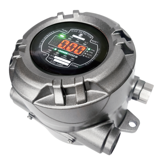
Page 6: Front Display Configuration
Cable gland It is power and signal cable inlet. NAME DESCRIPTIONS [Table 1. GTD-5100F Component Description] Power LED(Green) When the power (AC 24V 24V) is supplied normally, LED lights on. Trouble LED Displayed when fault is detected during gas detector self-test. -
Page 7: Installation
GTD-5100F 5. Installation 5. Installation www.gastron.com Instruction Manual 12_13 5.1. Terminal Configuration 5.2. Power and 4-20mA Signal Configuration ■ <Warning - Do not open when electrical current is flowing> ■ <Warning - Turn off power before connecting power terminal> ■ Loosen case cover set screw located in the front part of the detector and detach the case cover. - Page 8 GTD-5100F 5. Installation 5. Installation www.gastron.com Instruction Manual 14_15 5.2.3. Power and 4~20mA 3 Sink Configuration 5.4. RS-485 Terminal Configuration ■ Connect (+) and (-) terminals for 4-20 mA sink output at ■ Connect RS-485A and RS-485B of CN17 with MODBUS Master terminal as shown below.
- Page 9 GTD-5100F 6. Operation 6. Operation www.gastron.com Instruction Manual 16_17 6.1. Power On 6.2. Measuring Mode ■ After checking wiring and power voltage, turn on the power switch located at the front part. - It displays gas concentration received from sensor on FND digital display in numbers and the current ■...
- Page 10 GTD-5100F 7. System Mode 7. System Mode www.gastron.com Instruction Manual 18_19 7.1. Mode Configuration LEVEL1 LEVEL2 LEVEL3 DEFAULT ZERO NO , YES ■ This device consists of the following menu configuration. Current Zero Measurement TYPE Menu Display Description Notes WAIT(Wait)
- Page 11 GTD-5100F 7. System Mode 7. System Mode www.gastron.com Instruction Manual 20_21 7.3. Configuration Mode - It is a mode that sets sensor calibration frequency in a unit of month. Pressing ▲"key or "▼"key increases or decrease number, respectively. - When "FUNC" key is pressed for 2 sec or longer in measuring mode, it enters password required step.
-
Page 12: Zero Calibration
GTD-5100F 7. System Mode 7. System Mode www.gastron.com Instruction Manual 22_23 7.4. Program Setting 7.5. Zero Calibration - - When "FUNC" key is pressed for 2 sec or longer in gas concentration display mode, it enters menu - When "FUNC" key is pressed for 2 sec or longer in measuring mode, it enters menu selection mode. -
Page 13: Span Calibration
GTD-5100F 7. System Mode 7. System Mode www.gastron.com Instruction Manual 24_25 7.6. Span Calibration 7.7. Alarm Data Setting (Alarm Mode) - When "FUNC" key is pressed for 2 sec or longer in measuring mode, it enters menu selection mode. - - When "FUNC" key is pressed for 2 sec or longer in gas concentration display mode at the same time, UP key or DOWN key to select "CALB"... - Page 14 GTD-5100F 7. System Mode 7. System Mode www.gastron.com Instruction Manual 26_27 - It is a mode that sets Dead band value for Alarm1 operation. Use " "UP key or DOWN key to set a value. - It is a mode that sets Dead band value for Alarm1 operation. Use UP key or DOWN key to set a value.
-
Page 15: Troubleshooting
GTD-5100F 8. Troubleshooting 8. Troubleshooting www.gastron.com Instruction Manual 28_29 8.1. Fault List 8.3. Recovery List FAULT DESCRIPTION & CONDITION CAUSE CAUSE SOLUTION When a sensor cartridge is not equipped in the 1) Sensor cartridge connection fault 1) Check status of sensor cartridge connector... -
Page 16: Interface Configuration
GTD-5100F 9. Interface Configuration 9. Interface Configuration www.gastron.com Instruction Manual 30_31 9.1. MODBUS RS485 9.2. MODBUS/TCP Interface 9.1.1. Interface setting 9.2.1. Interface setting ■ Data Format: RTU ■ Stop bit: 1bits ■ MODBUS Port Number 502 ■ Baud rate: 9600 bps ■... - Page 17 GTD-5100F 9. Interface Configuration 9. Interface Configuration www.gastron.com Instruction Manual 32_33 TYPE ADDRESS BITS DESCRIPTION TYPE ADDRESS BITS DESCRIPTION Decimal point indicator(0~3) 40020 BIT0~15 High Scale Value in floating point format word 1 of 2 Real type high scale setting...
-
Page 18: Drawings And Dimensions
It can be used in ZONE 1 (ONE) and ZONE 2 (TWO) hazardous sites. ■ Allowable temperature is 85 C or below, which corresponds to T6. [Figure 7. GTD-5100F Drawing and Dimensions] ■ Use with surrounding temperature in a range of -20 C ~ 60 °C. -
Page 19: Revision History
GTD-5100F 11. Precautions before Installation 12. Revision History www.gastron.com Instruction Manual 36_37 ■ Installation Height: 1,000 M below sea level VERSION CONTENTS DATE ■ Relative Humidity: 5% ~ 99% (Non-condensing) Rev. 1.0 Initial Revision of Manual 2016.09.29 ■ Installation Site: Indoor and Outdoor Rev.
Need help?
Do you have a question about the GTD-5100F and is the answer not in the manual?
Questions and answers