
Related Manuals for Stryker MV3 5900


Summary of Contents for Stryker MV3 5900
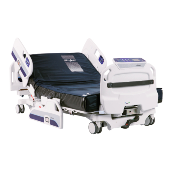
- Page 1 M M V V 3 3 ™ ™ B B a a r r i i a a t t r r i i c c B B e e d d M M a a i i n n t t e e n n a a n n c c e e M M a a n n u u a a l l 5900 5900-009-002 Rev A.0 2019/08...
- Page 3 General warning Caution Warning; electricity Fuse rating Do not drill Hydraulic oil pressure Pinch/crush hazard Non-ionizing radiation Catalogue number Serial number European medical device CE mark Authorized representative in the European Community For US Patents see www.stryker.com/patents Manufacturer 5900-009-002 Rev A.0...
- Page 4 Safe working load Mass of equipment Maximum patient weight Adult patient biometrics Alternating current Direct current Duty cycle of product ≤2m ≥18m Unit provides terminal for connection of a potential equalization conductor. The potential equalization conductor provides direct connection between the unit and potential equalization busbar of the electrical installation.
-
Page 5: Table Of Contents
T T a a b b l l e e o o f f C C o o n n t t e e n n t t s s Warning/Caution/Note Definition ..........................3 Summary of safety precautions ..........................4 Introduction ................................5 Product description ..............................5 Indications for use..............................5 Clinical benefits ..............................5... - Page 6 Deck pan assembly, seat deck, patient left ......................55 Deck assembly, head section ..........................56 Deck pan assembly, head deck, patient right ......................65 Deck pan assembly, head deck, patient left ......................66 Lock assembly, head deck position ........................67 Deck assembly, knee section ..........................68 Deck pan assembly, knee deck, patient right ......................72 Deck pan assembly, knee deck, patient left...
- Page 7 W W a a r r n n i i n n g g / / C C a a u u t t i i o o n n / / N N o o t t e e D D e e f f i i n n i i t t i i o o n n The words W W A A R R N N I I N N G G , C C A A U U T T I I O O N N , and N N O O T T E E carry special meanings and should be carefully reviewed.
- Page 8 • Do not use this product for psychiatric, pediatric, or home health care use. • Do not use this product in an oxygen rich environment. • Always use Stryker approved mattresses that have been tested for compatibility with the product frame to avoid the risk of patient entrapment.
-
Page 9: Expected Service Life
P P r r o o d d u u c c t t d d e e s s c c r r i i p p t t i i o o n n The Stryker model 5900 M M V V 3 3 ™ ™ bariatric hospital bed is an AC-powered adjustable hospital bed designed to be utilized with a patient support surface matching the deck size of the bed frame. - Page 10 S S p p e e c c i i f f i i c c a a t t i i o o n n s s W W A A R R N N I I N N G G - - Always use Stryker approved mattresses that have been tested for compatibility with the product frame to avoid the risk of patient entrapment.
-
Page 11: Specifications
Battery voltage 12 VDC (x2) (Stryker part number: 5900280025) N N o o t t e e - - Always replace with Stryker approved batteries. Duty cycle 2 minutes ON, 18 minutes OFF Application environments 1, 2, 3, and 5 per IEC 60601-2-52 Maximum acoustic sound pressure <... - Page 12 C C o o n n t t a a c c t t i i n n f f o o r r m m a a t t i i o o n n Contact Stryker Customer Service or Technical Support at: 1-800-327-0770.
- Page 13 Competent authority of the European Member State where the user and/or patient is established. To view your operations or maintenance manual online, see https://techweb.stryker.com/. Have the serial number (A) of your Stryker product available when calling Stryker Customer Service or Technical Support. Include the serial number in all written communication.
-
Page 14: Preventive Maintenance
Remove the product from service before you perform the preventive maintenance inspection. Make sure that all items listed during annual preventive maintenance for all Stryker Medical products. You may need to perform preventive maintenance checks more often based on your level of product usage. Service only by qualified personnel. - Page 15 Inspect hi-lo actuators for oil leaks Inspect footboard connector housing for cracks or damage All motions function Nurse call functions Auxiliary outlets function (test ground fault interrupter) Replace batteries (one year expected service life) Set clock to local date and time Product serial number: Completed by: Date:...
-
Page 16: Error Codes
E E r r r r o o r r c c o o d d e e s s Error codes are detailed in the table below. T T r r o o u u b b l l e e s s h h o o o o t t i i n n g g E E r r r r o o r r c c o o d d e e C C a a u u s s e e 0.02... - Page 17 T T r r o o u u b b l l e e s s h h o o o o t t i i n n g g E E r r r r o o r r c c o o d d e e C C a a u u s s e e 0.13 ACB HILO foot board is not responding...
-
Page 18: Maintenance Menu
T T r r o o u u b b l l e e s s h h o o o o t t i i n n g g E E r r r r o o r r c c o o d d e e C C a a u u s s e e 0.27 AVB board is not responding... - Page 19 T T r r o o u u b b l l e e s s h h o o o o t t i i n n g g E E r r r r o o r r c c o o d d e e C C a a u u s s e e 1.14 HILO head drive circuit error...
- Page 20 T T r r o o u u b b l l e e s s h h o o o o t t i i n n g g E E r r r r o o r r c c o o d d e e C C a a u u s s e e Knee drive circuit malfunction 1.
- Page 21 T T r r o o u u b b l l e e s s h h o o o o t t i i n n g g E E r r r r o o r r c c o o d d e e C C a a u u s s e e 1.29 SMB head configuration error...
- Page 22 E E l l e e c c t t r r i i c c a a l l d d i i a a g g r r a a m m FOOT BRACKET 5900200135 AVB 5900280034 HEAD ACTUATOR W/ CPR HILO FOOT ACTUATOR HILO HEAD ACTUATOR FOOT ACTUATOR...
- Page 23 C C a a b b l l e e r r o o u u t t i i n n g g 5900-009-002 Rev A.0...
-
Page 24: Language
M M a a i i n n t t e e n n a a n n c c e e m m e e n n u u The maintenance menu provides access to the following settings: • Language •... -
Page 25: Actuator Maintenance
5. Highlight P P r r e e s s s s √ √ t t o o s s e e t t and press E E n n t t e e r r to set the product clock. A A c c t t u u a a t t o o r r m m a a i i n n t t e e n n a a n n c c e e C C A A U U T T I I O O N N - - Always make sure that the product is clear of obstacles before you use motion functions. -
Page 26: Angle Maintenance
6. Highlight P P r r o o c c e e e e d d and press E E n n t t e e r r to access scale maintenance. C C a a l l i i b b r r a a t t e e s s c c a a l l e e N N o o t t e e - - Make sure that the product litter deck is flat and horizontal before you calibrate the scale. -
Page 27: Width Maintenance
To calibrate the angles: 1. Enter the Maintenance menu (page 20). 2. Enter Actuator maintenance (page 21). 3. Highlight C C a a l l i i b b r r a a t t e e a a n n g g l l e e s s and press E E n n t t e e r r . 4. -
Page 28: Patient Station
P P a a t t i i e e n n t t s s t t a a t t i i o o n n The patient station menu allows the user to set the product to patient station interface. Patient station provides access to the following settings: •... -
Page 29: Service
• Do not place unprotected circuit boards on the floor. N N o o t t e e - - Always ship back circuit boards to Stryker in the same antistatic bags that the new boards were originally shipped in. - Page 30 C C a a s s t t e e r r r r e e p p l l a a c c e e m m e e n n t t C C A A U U T T I I O O N N •...
- Page 31 8. Using a #2 Phillips screwdriver, remove the two screws from the power supply mounting bracket closest to the outside of the bed. 9. Hinge the batteries down. C C A A U U T T I I O O N N •...
- Page 32 F F o o o o t t b b o o a a r r d d k k e e y y p p a a d d / / d d i i s s p p l l a a y y r r e e p p l l a a c c e e m m e e n n t t T T o o o o l l s s r r e e q q u u i i r r e e d d : : •...
- Page 33 8. Disconnect the keypad/display cable. Remove and save the keypad display. 9. Remove the footboard from the product. 10. Using a #2 Phillips screwdriver, remove and save the two screws that secure the footboard main cable to the bottom of the footboard.
- Page 34 • Syn-Tech grease (3000-200-719) P P r r o o c c e e d d u u r r e e : : 1. Raise the product to the highest height position. 2. On the footboard control panel, press E E n n t t e e r r to access the S S e e t t t t i i n n g g s s menu. 3.
- Page 35 L L i i f f t t a a c c t t u u a a t t o o r r r r e e p p l l a a c c e e m m e e n n t t ( ( h h e e a a d d / / f f o o o o t t ) ) T T o o o o l l s s r r e e q q u u i i r r e e d d : : •...
- Page 36 P P r r o o c c e e d d u u r r e e : : 1. Push down on the brake pedal to apply the brake. 2. On the footboard control panel, press E E n n t t e e r r to access the S S e e t t t t i i n n g g s s menu. 3.
- Page 37 11. Using a #2 Phillips screwdriver, remove and save the two screws that secure the inspection cover to the base frame weldment. Remove and save the inspection cover. 12. Using a #2 Phillips screwdriver, remove and save the two screws that secure the board assembly to the base frame weldment.
- Page 38 • Needle nose pliers • Syn-Tech grease (3000-200-719) P P r r o o c c e e d d u u r r e e : : 1. Raise the product to the highest height position. 2. On the footboard control panel, press E E n n t t e e r r to access the S S e e t t t t i i n n g g s s menu. 3.
- Page 39 • 3/8” hex driver • 7/16” socket P P r r o o c c e e d d u u r r e e : : 1. Using a 3/8” hex driver, attach the patient helper mounting bracket with the four supplied screws. N N o o t t e e - - Make sure that the armrest pin faces upward.
- Page 40 T T o o p p l l e e v v e e l l a a s s s s e e m m b b l l y y 5900103001 Rev G (Reference only) 2X TORQUE TO 150-180in/lbs TORQUE TO 150-180in/lbs...
- Page 41 5900-009-002 Rev A.0...
- Page 42 TORQUE TO 50-70in/lbs TORQUE TO 50-70in/lbs TORQUE TO 70-90in/lbs 5900-009-002 Rev A.0...
-
Page 43: Deck Assembly, Seat Section
I I t t e e m m N N u u m m b b e e r r N N a a m m e e Q Q u u a a n n t t i i t t y y 5900200119 Hi-low frame assembly 5900340082... - Page 44 I I t t e e m m N N u u m m b b e e r r N N a a m m e e Q Q u u a a n n t t i i t t y y 5900320016 Washer, EPDM rubber 0.49ID x 1.063OD x 0.093W...
- Page 45 U U p p p p e e r r f f r r a a m m e e a a s s s s e e m m b b l l y y 5900200120 Rev E (Reference only) 5900-009-002 Rev A.0...
- Page 46 2X / BOX 2X / BOX DETAIL A DETAIL B 5900-009-002 Rev A.0...
- Page 47 17 2X 18 2X DETAIL C 19 3X DETAIL D 5900-009-002 Rev A.0...
- Page 48 17 4X 27 2X 28 2X DETAIL E 17 4X 17 2X Torque item 11 to 50-70 in-lb 5900-009-002 Rev A.0...
- Page 49 50 6X I I t t e e m m N N u u m m b b e e r r N N a a m m e e Q Q u u a a n n t t i i t t y y 5900240094 Upper frame weldment 5900310020...
- Page 50 I I t t e e m m N N u u m m b b e e r r N N a a m m e e Q Q u u a a n n t t i i t t y y 5900200164 ASM, HRNS support span 5900340090...
- Page 51 D D e e c c k k a a s s s s e e m m b b l l y y , , s s e e a a t t s s e e c c t t i i o o n n 5900200041 Rev E (Reference only) 5900-009-002 Rev A.0...
- Page 52 Torque item 14 to 25-30 in-lb Torque item 14 to 25-30 in-lb 5900-009-002 Rev A.0...
- Page 53 5900-009-002 Rev A.0...
- Page 54 5900-009-002 Rev A.0...
- Page 55 5900-009-002 Rev A.0...
-
Page 56: Deck Pan Assembly, Seat Deck, Patient Left
I I t t e e m m N N u u m m b b e e r r N N a a m m e e Q Q u u a a n n t t i i t t y y 5900240025 Frame weldment, seat deck 5900200038... - Page 57 I I t t e e m m N N u u m m b b e e r r N N a a m m e e Q Q u u a a n n t t i i t t y y 5900340097 Screw, sems pan PH #6-32x1-1/2LG INT wash zinc PL...
- Page 58 D D e e c c k k p p a a n n a a s s s s e e m m b b l l y y , , s s e e a a t t d d e e c c k k , , p p a a t t i i e e n n t t r r i i g g h h t t 5900200038 Rev A (Reference only) I I t t e e m m N N u u m m b b e e r r...
- Page 59 D D e e c c k k p p a a n n a a s s s s e e m m b b l l y y , , s s e e a a t t d d e e c c k k , , p p a a t t i i e e n n t t l l e e f f t t 5900200039 Rev A (Reference only) I I t t e e m m N N u u m m b b e e r r...
- Page 60 D D e e c c k k a a s s s s e e m m b b l l y y , , h h e e a a d d s s e e c c t t i i o o n n 5900200055 Rev E (Reference only) 5900-009-002 Rev A.0...
- Page 61 Torque item 16 to 25-30 in-lb Torque item 16 to 25-30 in-lb 5900-009-002 Rev A.0...
- Page 62 5900-009-002 Rev A.0...
- Page 63 5900-009-002 Rev A.0...
- Page 64 1.75±0.125 12.75±0.125 5900-009-002 Rev A.0...
- Page 65 5900-009-002 Rev A.0...
- Page 66 5900-009-002 Rev A.0...
-
Page 67: Deck Pan Assembly, Head Deck, Patient Right
I I t t e e m m N N u u m m b b e e r r N N a a m m e e Q Q u u a a n n t t i i t t y y 5900240042 Deck weldment, head section 5900200068... - Page 68 I I t t e e m m N N u u m m b b e e r r N N a a m m e e Q Q u u a a n n t t i i t t y y 5900340101 Screw, rd hd flg hex drive 1/4-unc x 3/8lg zinc...
- Page 69 D D e e c c k k p p a a n n a a s s s s e e m m b b l l y y , , h h e e a a d d d d e e c c k k , , p p a a t t i i e e n n t t r r i i g g h h t t 5900200068 Rev A (Reference only) I I t t e e m m N N u u m m b b e e r r...
- Page 70 D D e e c c k k p p a a n n a a s s s s e e m m b b l l y y , , h h e e a a d d d d e e c c k k , , p p a a t t i i e e n n t t l l e e f f t t 5900200069 Rev A (Reference only) I I t t e e m m N N u u m m b b e e r r...
- Page 71 L L o o c c k k a a s s s s e e m m b b l l y y , , h h e e a a d d d d e e c c k k p p o o s s i i t t i i o o n n 5900200051 Rev A (Reference only) I I t t e e m m N N u u m m b b e e r r...
- Page 72 D D e e c c k k a a s s s s e e m m b b l l y y , , k k n n e e e e s s e e c c t t i i o o n n 5900200056 Rev E (Reference only) 5900-009-002 Rev A.0...
- Page 73 5900-009-002 Rev A.0...
- Page 74 Torque item 15 to 25-30 in-lb 5900-009-002 Rev A.0...
-
Page 75: Deck Pan Assembly, Knee Deck, Patient Right
I I t t e e m m N N u u m m b b e e r r N N a a m m e e Q Q u u a a n n t t i i t t y y 5900240045 Deck weldment, knee section 5900200072... - Page 76 D D e e c c k k p p a a n n a a s s s s e e m m b b l l y y , , k k n n e e e e d d e e c c k k , , p p a a t t i i e e n n t t r r i i g g h h t t 5900200073 Rev A (Reference only) I I t t e e m m N N u u m m b b e e r r...
- Page 77 D D e e c c k k p p a a n n a a s s s s e e m m b b l l y y , , k k n n e e e e d d e e c c k k , , p p a a t t i i e e n n t t l l e e f f t t 5900200072 Rev A (Reference only) I I t t e e m m N N u u m m b b e e r r...
- Page 78 D D e e c c k k a a s s s s e e m m b b l l y y , , f f o o o o t t s s e e c c t t i i o o n n 5900200057 Rev G (Reference only) 5900-009-002 Rev A.0...
- Page 79 Torque item 16 to 25-30 in-lb Torque item 16 to 25-30 in-lb 5900-009-002 Rev A.0...
- Page 80 5900-009-002 Rev A.0...
- Page 81 5900-009-002 Rev A.0...
- Page 82 5900-009-002 Rev A.0...
- Page 83 I I t t e e m m N N u u m m b b e e r r N N a a m m e e Q Q u u a a n n t t i i t t y y 5900240106 Deck weldment, foot section 5900200074...
- Page 84 I I t t e e m m N N u u m m b b e e r r N N a a m m e e Q Q u u a a n n t t i i t t y y 5900330020 Bushing, flg 0.500X0.625X0.313LG (flg 0.875X0.062)
- Page 85 D D e e c c k k p p a a n n a a s s s s e e m m b b l l y y , , f f o o o o t t d d e e c c k k , , p p a a t t i i e e n n t t r r i i g g h h t t 5900200075 Rev A (Reference only) I I t t e e m m N N u u m m b b e e r r...
- Page 86 D D e e c c k k p p a a n n a a s s s s e e m m b b l l y y , , f f o o o o t t d d e e c c k k , , p p a a t t i i e e n n t t l l e e f f t t 5900200074 Rev A (Reference only) I I t t e e m m N N u u m m b b e e r r...
- Page 87 H H I I L L O O f f r r a a m m e e a a s s s s e e m m b b l l y y 5900200122 Rev D (Reference only) 5900-009-002 Rev A.0...
- Page 88 5900-009-002 Rev A.0...
-
Page 89: Lower Frame Assembly
Torque item 11 to 50-70 in-lb DETAIL A Torque item 11 to 50-70 in-lb I I t t e e m m N N u u m m b b e e r r N N a a m m e e Q Q u u a a n n t t i i t t y y 5900200124 Caster frame assembly... - Page 90 I I t t e e m m N N u u m m b b e e r r N N a a m m e e Q Q u u a a n n t t i i t t y y 5900350017 Snap-cap cover #12/12 white 5900350003...
- Page 91 L L o o w w e e r r f f r r a a m m e e a a s s s s e e m m b b l l y y 5900200123 Rev B (Reference only) Torque item 2 to 150-180 in-lb FOOT...
- Page 92 I I t t e e m m N N u u m m b b e e r r N N a a m m e e Q Q u u a a n n t t i i t t y y 5900280027 Sensor assembly, load cell K-SBS 5900330020...
- Page 93 C C a a s s t t e e r r f f r r a a m m e e a a s s s s e e m m b b l l y y 5900200124 Rev D (Reference only) RED SIDE TOWARDS FOOT END OF BED RED SIDE TOWARDS...
- Page 94 APPLY NS-18191-G GREASE TO SHAFT (TYPICAL BOTH ENDS) CENTER BRAKE CHANGE LEVER DETAIL ( TYPICAL BOTH HEAD AND FOOT) 5900-009-002 Rev A.0...
- Page 95 TORQUE TO 140-160in/lbs TYP TORQUE TO 140-160in/lbs TYP CASTER CHANGE LEVER DETAILS ( TYPICAL 4 CORNERS) TORQUE TO 50-70in/lbs TYP GROUND STRAP INSTALLED ON PATIENT LEFT HEAD & PATIENT RIGHT FOOT INNER FRAME RAILS. ORIENT GROUND STRAP AS SHOWN USING ANTI-ROTATE CLIP. BRAKE SWITCH INSTALLED ON HEAD END ONLY TORQUE TO...
- Page 96 I I t t e e m m N N u u m m b b e e r r N N a a m m e e Q Q u u a a n n t t i i t t y y 5900200118 Frame weldment, caster frame with inserts...
- Page 97 R R a a i i l l a a s s s s e e m m b b l l y y , , h h e e a a d d 5900200130 Rev C (right) (Reference only) 5900200131 Rev C (left) (Reference only) ROUTE ARM CABLES UNDER POSTS &...
- Page 98 INSTALL GEARS WITH ARROWS POINTING TO TOP SCREW RELATIVE TO ARM CENTERLINE. TYPICAL BOTH ARMS. START SCREWS IN THREADS - DO NOT TIGHTEN AT THIS TIME. CONNECT TO 6-PIN HEADER ON PCBA CONNECT LOCK HARNESS CONNECTOR DURING LATCH ASSEMBLY INSTALLATION. CONNECT RAIL POSITION HARNESS TO CORRESPONDING SWITCHES, ORIENT AND INSTALL AS SHOWN.
- Page 99 RACK MESH ADJUSTING SET SCREW APPLY NS-18191-G GREASE TO LENGTH OF RACK APPLY NS-18191-G AFTER MESH IS TIGHT, TORQUE ALL GEAR GREASE TO LENGTH SCREWS TO 45IN/LB (TWICE AROUND) OF RACK TIGHTEN RACK MESH SET SCREW TO ENSURE GEAR MESH IS TIGHT. FUNCTIONALLY CYCLE TEST TO ENSURE CORRECT SETTING FOR GRAVITY FALL AND "HITCH"...
- Page 100 CABLE TIE WIRES NEATLY TO BACKPLATE ROUTE HARNESSES UNDER PLATE TABS AS SHOWN. CABLE TIE WIRES NEATLY TO BACKPLATE LOOP RAIL ARM HARNESS AS SHOWN, ORIENT P-CLIP HORIZONTALLY. CONNECT TO PCBA. LOOP RAIL ARM HARNESS AS SHOWN, ORIENT P-CLIP HORIZONTALLY. CONNECT TO PCBA.
-
Page 101: Bracket Assembly, Lower Rail Slide
REMOVE ADHESIVE BACKING PAPER, AND ADHERE TO BLOWMOLD PANEL. REMOVE ADHESIVE BACKING PAPER, AND ADHERE TO SPEAKER COVER AND BLOW MOLD PANEL WHILE ALIGNING WITH COVER PLATE. CUTOUT "A" ROUTE HARNESS INTERNALLY THRU PANEL CUTOUT "A", TO CUTOUT "C". ROUTE HARNESS INTERNALLY THRU PANEL CUTOUT "B"... - Page 102 R R a a i i l l a a s s s s e e m m b b l l y y , , h h e e a a d d 5 5 9 9 0 0 0 0 2 2 0 0 0 0 1 1 3 3 0 0 R R e e v v C C ( ( R R e e f f e e r r e e n n c c e e o o n n l l y y ) ) I I t t e e m m N N u u m m b b e e r r N N a a m m e e...
- Page 103 R R a a i i l l a a s s s s e e m m b b l l y y , , h h e e a a d d 5 5 9 9 0 0 0 0 2 2 0 0 0 0 1 1 3 3 0 0 R R e e v v C C ( ( R R e e f f e e r r e e n n c c e e o o n n l l y y ) ) I I t t e e m m N N u u m m b b e e r r N N a a m m e e...
- Page 104 R R a a i i l l a a s s s s e e m m b b l l y y , , h h e e a a d d 5 5 9 9 0 0 0 0 2 2 0 0 0 0 1 1 3 3 1 1 R R e e v v C C ( ( R R e e f f e e r r e e n n c c e e o o n n l l y y ) ) I I t t e e m m N N u u m m b b e e r r N N a a m m e e...
- Page 105 R R a a i i l l a a s s s s e e m m b b l l y y , , f f o o o o t t 5900200132 Rev C (right) (Reference only) 5900200133 Rev C (left) (Reference only) ROUTE ARM CABLES UNDER POSTS &...
- Page 106 CONNECT TO 6-PIN HEADER ON PCBA CONNECT LOCK HARNESS CONNECTOR DURING LATCH ASSEMBLY INSTALLATION. CONNECT RAIL POSITION HARNESS TO CORRESPONDING SWITCHES, ORIENT AND INSTALL AS SHOWN. RACK MESH ADJUSTING SET SCREW APPLY NS-18191-G GREASE TO LENGTH OF RACK AFTER MESH IS TIGHT, TORQUE ALL GEAR SCREWS TO 45IN/LB (TWICE AROUND) TIGHTEN RACK MESH SET SCREW TO ENSURE GEAR APPLY NS-18191-G...
- Page 107 0.25 8.00 PLACE TAPE APPROXIMATELY AS SHOWN ON BACKPLATE 5900-009-002 Rev A.0...
- Page 108 CABLE TIE WIRES NEATLY TO BACKPLATE ROUTE HARNESSES UNDER CABLE TIE WIRES NEATLY PLATE TABS AS SHOWN. TO BACKPLATE LOOP RAIL ARM HARNESS AS SHOWN, ORIENT P-CLIP HORIZONTALLY. CONNECT TO PCBA. WIRE HARNESS ROUTING ROUTE ALL HARNESSES AS SHOWN. 5900-009-002 Rev A.0...
- Page 109 ROUTE KEYPAD RIBBON HARNESS THRU THIS NOTCH DURING ASSEMBLY; PLUG INTO PCBA HEADER. LOCATE CPR LABEL APPROXIMATELY AS SHOWN, CENTERED ON RAIL ARM COVER. R R a a i i l l a a s s s s e e m m b b l l y y , , f f o o o o t t 5 5 9 9 0 0 0 0 2 2 0 0 0 0 1 1 3 3 2 2 R R e e v v C C ( ( R R e e f f e e r r e e n n c c e e o o n n l l y y ) ) I I t t e e m m N N u u m m b b e e r r N N a a m m e e...
- Page 110 R R a a i i l l a a s s s s e e m m b b l l y y , , f f o o o o t t 5 5 9 9 0 0 0 0 2 2 0 0 0 0 1 1 3 3 2 2 R R e e v v C C ( ( R R e e f f e e r r e e n n c c e e o o n n l l y y ) ) I I t t e e m m N N u u m m b b e e r r N N a a m m e e...
- Page 111 R R a a i i l l a a s s s s e e m m b b l l y y , , f f o o o o t t 5 5 9 9 0 0 0 0 2 2 0 0 0 0 1 1 3 3 3 3 R R e e v v C C ( ( R R e e f f e e r r e e n n c c e e o o n n l l y y ) ) I I t t e e m m N N u u m m b b e e r r N N a a m m e e...
- Page 112 T T i i m m i i n n g g l l i i n n k k a a s s s s e e m m b b l l y y 5900200121 Rev C (Reference only) I I t t e e m m N N u u m m b b e e r r N N a a m m e e...
- Page 113 R R a a i i l l a a r r m m a a s s s s e e m m b b l l y y , , p p o o w w e e r r / / c c o o m m m m u u n n i i c c a a t t i i o o n n 5900200061 Rev B (Reference only) (SEE DETAIL B) DETAIL B...
- Page 114 R R a a i i l l a a r r m m a a s s s s e e m m b b l l y y , , n n u u r r s s e e c c a a l l l l / / s s p p e e a a k k e e r r 5900200062 Rev B (Reference only) (SEE DETAIL B) DETAIL B...
- Page 115 R R a a i i l l a a r r m m a a s s s s e e m m b b l l y y , , n n o o c c a a b b l l e e 5900200060 Rev A (Reference only) I I t t e e m m N N u u m m b b e e r r...
- Page 116 B B r r a a c c k k e e t t a a s s s s e e m m b b l l y y , , l l o o w w e e r r r r a a i i l l s s l l i i d d e e 5900200047 Rev B (Reference only) I I t t e e m m N N u u m m b b e e r r...
- Page 117 L L a a t t c c h h l l o o c c k k a a s s s s e e m m b b l l y y , , l l e e f f t t h h e e a a d d / / r r i i g g h h t t f f o o o o t t - - 5 5 9 9 0 0 0 0 2 2 0 0 0 0 0 0 2 2 3 3 Rev B (Reference only) I I t t e e m m N N u u m m b b e e r r...
- Page 118 L L a a t t c c h h l l o o c c k k a a s s s s e e m m b b l l y y , , r r i i g g h h t t h h e e a a d d / / l l e e f f t t f f o o o o t t - - 5 5 9 9 0 0 0 0 2 2 0 0 0 0 0 0 2 2 4 4 Rev B (Reference only) I I t t e e m m N N u u m m b b e e r r...
- Page 119 P P o o w w e e r r s s u u p p p p l l y y c c o o r r d d 0039-254-000 Rev AA (Reference only) 5900-009-002 Rev A.0...
-
Page 120: Power Supply Cord
A A c c c c e e s s s s o o r r y y c c o o r r d d , , t t y y p p e e B B 1 1 2 2 0 0 V V 5900430166 Rev A (Reference only) I I t t e e m m N N u u m m b b e e r r... - Page 121 F F o o o o t t b b o o a a r r d d a a s s s s e e m m b b l l y y - - 5 5 9 9 0 0 0 0 2 2 0 0 0 0 0 0 2 2 5 5 Rev B (Reference only) 20 2X 5900-009-002 Rev A.0...
- Page 122 16 2X 23 2X I I t t e e m m N N u u m m b b e e r r N N a a m m e e Q Q u u a a n n t t i i t t y y 5900650002 Panel, footboard FSC 60°...
- Page 123 I I t t e e m m N N u u m m b b e e r r N N a a m m e e Q Q u u a a n n t t i i t t y y 5900370102 Rivet, 3/16 x 5/16"...
- Page 124 E E x x p p a a n n d d a a b b l l e e h h e e a a d d b b o o a a r r d d a a s s s s e e m m b b l l y y - - 5 5 9 9 0 0 0 0 2 2 0 0 0 0 0 0 2 2 6 6 Rev D (Reference only) 21 4X 5900-009-002 Rev A.0...
- Page 125 19 2X I I t t e e m m N N u u m m b b e e r r N N a a m m e e Q Q u u a a n n t t i i t t y y 5900650003 Panel, expandable headboard, patient right, large...
- Page 126 I I t t e e m m N N u u m m b b e e r r N N a a m m e e Q Q u u a a n n t t i i t t y y 5900690094 Label, transport warning 5900310017...
- Page 127 E E M M C C i i n n f f o o r r m m a a t t i i o o n n W W A A R R N N I I N N G G - - The use of accessories, transducers, and cables, other than those specified or provided by the manufacturer, could result in increased electromagnetic emissions or decreased electromagnetic immunity and result in improper operation.
- Page 128 G G u u i i d d a a n n c c e e a a n n d d m m a a n n u u f f a a c c t t u u r r e e r r ’ ’ s s d d e e c c l l a a r r a a t t i i o o n n - - e e l l e e c c t t r r o o m m a a g g n n e e t t i i c c i i m m m m u u n n i i t t y y Main power quality should Electrostatic fast transient/ +2 kV for power supply lines...
- Page 129 Portable and mobile RF communications equipment should be used no closer to any part of the 5900 M M V V 3 3 Bariatric bed, including cables, than the recommended separation distance calculated from the equation appropriate for the frequency of the transmitter. Recommended separation distance D=(1.2) (√...
- Page 130 W W A A R R N N I I N N G G • Portable RF communications equipment, including peripherals such as antenna cables and external antennas, should be no closer than 12 inches (30 cm) to any part of M M V V 3 3 , including cables specified by the manufacturer. •...
- Page 131 L L e e n n g g t t h h ( ( m m ) ) C C a a b b l l e e Nurse call (DB-37) Nurse call (1/4 in.) 5900-009-002 Rev A.0...
- Page 132 0 0 0 0 3 3 9 9 - - 2 2 5 5 4 4 - - 0 0 0 0 0 0 0039-254-000 5900-009-002 Rev A.0...
- Page 133 5 5 9 9 0 0 0 0 4 4 0 0 0 0 0 0 3 3 7 7 , , 5 5 9 9 0 0 0 0 4 4 0 0 0 0 0 0 4 4 0 0 5900400037 5900400040 5900-009-002 Rev A.0...
- Page 134 5 5 9 9 0 0 0 0 4 4 0 0 0 0 0 0 3 3 8 8 5900400038 5900-009-002 Rev A.0...
- Page 135 5 5 9 9 0 0 0 0 4 4 7 7 0 0 0 0 1 1 7 7 5900470017 5900-009-002 Rev A.0...
- Page 136 5 5 9 9 0 0 0 0 4 4 7 7 0 0 0 0 1 1 8 8 , , 5 5 9 9 0 0 0 0 4 4 7 7 0 0 0 0 1 1 9 9 5900470018 5900470019 5900-009-002 Rev A.0...
- Page 138 Stryker Medical 3800 E. Centre Avenue Portage, MI 49002 5900-009-002 Rev A.0 2019/08 WCR: AA.15...
Need help?
Do you have a question about the MV3 5900 and is the answer not in the manual?
Questions and answers