
Related Manuals for Stryker Model 1004


Summary of Contents for Stryker Model 1004
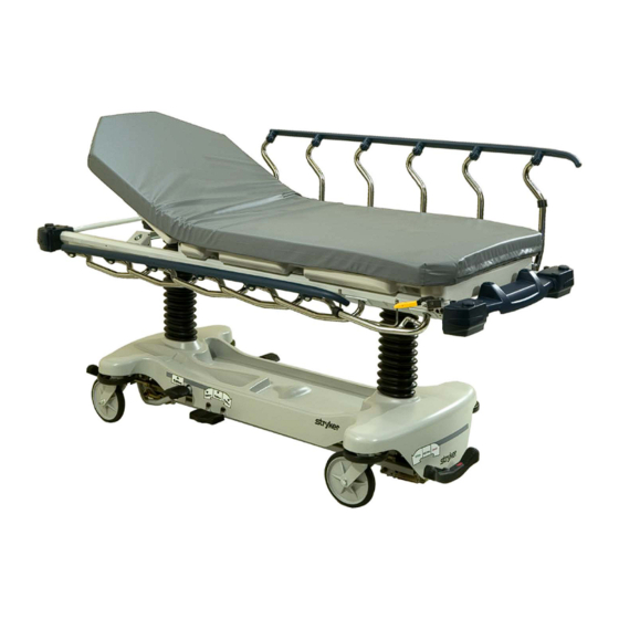
- Page 1 Operations Medical Manual Model 1004 ASC Stretcher Important Information File in your For parts or technical maintenance assistance call records 800 327 0770 (option 2)
-
Page 2: Table Of Contents
Table of Contents Introduction ................2−3 Operating Base Controls . -
Page 3: Introduction
Introduction INTRODUCTION This manual is designed to assist you with the operation of the Model ASC Stretcher. Read it thoroughly be- fore using the equipment or beginning any maintenance on it. SPECIFICATIONS Maximum Weight Capacity 500 pounds Overall Stretcher Length 84”... - Page 4 Introduction Before operating this stretcher, it is important to read and understand all information in this manual. Carefully read and strictly follow the warnings and cautions listed on this page. WARNING Always apply the caster brakes when a patient is getting on or off the stretcher. Push on the stretcher to en- sure the brakes are securely locked.
-
Page 5: Operating Base Controls
Stretcher Operation OPERATING BASE CONTROLS − SIDE CONTROL FOOT END HEAD END Pump pedal (A) to raise the litter. Depress in the center of pedal (B) to lower both ends of the stretcher together. Depress the side of pedal (B) closest to the foot end of the stretcher to lower the foot end. -
Page 6: Raising And Lowering Litter Height
Stretcher Operation RAISING AND LOWERING LITTER HEIGHT − SIDE CONTROL CAUTION To avoid damage, remove any equipment that may be in the way before raising or lowering the litter height. To raise the litter height, pump pedal (A) repeatedly until the desired height is achieved (see illustration on page To lower both ends of the litter together, depress the center of pedal (B). -
Page 7: Applying The Brake System
Stretcher Operation APPLYING THE BRAKE SYSTEM Brake/Steer Pedal (Optional) FOOT END HEAD END Brake/Steer Pedal (Optional) NOTE For user convenience, a brake/steer control pedal is located on both ends of the stretcher. WARNING Always apply the caster brakes when a patient is getting on or off the stretcher. Push on the stretcher to en- sure the brakes are securely locked. -
Page 8: Using The Siderails
Stretcher Operation OPERATING THE GLIDEAWAYt SIDERAILS FOOT END NOTE Raising and lowering the siderails safely is a two−handed operation. Use one hand to hold and position the siderail and the other hand to operate the siderail latch. WARNING When lowering the siderail to the collapsed position, keep extremities of patients and staff away from the side- rail spindles or injury could occur. -
Page 9: Operating The Pneumatic Fowler
Stretcher Operation OPERATING THE PNEUMATIC FOWLER Squeeze either or both of the yellow Fowler handles (A) for pneumatic assist in lifting the Fowler to the desired height. Remove hand(s) from handle when the desired height is achieved. The optional drop seat/lift assist Fowler uses the weight of the patient for additional assistance with lifting the Fowler. -
Page 10: Operating The Optional 2−Stage Permanently Attached Iv Pole
Stretcher Operation OPERATING THE OPTIONAL 2−STAGE PERMANENTLY ATTACHED IV POLE DETAIL OF I.V. POLE LATCH NOTE The 2−stage permanently attached IV pole is an option and may have been installed at either the head, foot or both ends of the stretcher. The choice was made at the time the stretcher was purchased. To use the 2−stage permanently attached IV pole: 1. -
Page 11: Operating The Optional 3−Stage Permanently Attached Iv Pole
Stretcher Operation OPERATING THE OPTIONAL 3−STAGE PERMANENTLY ATTACHED IV POLE DETAIL OF I.V. POLE LATCH DETAIL OF I.V. POLE GRIP NOTE The 3−stage permanently attached IV pole is an option and may have been installed at either the head, foot or both ends of the stretcher. -
Page 12: Operating The Optional Foot Extension / Defibrillator Tray
Stretcher Operation USING THE OPTIONAL FOOT EXTENSION/DEFIBRILLATOR TRAY 1. To use as a defibrillator tray, pull out the top knob (A) and pivot the tray (B) over the foot extension (C) until the tray extends flat over the foot end of the stretcher. -
Page 13: Using The Optional Serving Tray
Stretcher Operation USING THE OPTIONAL SERVING TRAY FOOT Pull out on either end of the serving tray to extend it to the proper width to fit on top of the stretcher siderails. To store the serving tray in the optional serving tray holder/foot board, push in both ends of the serving tray and slide it into the holder. -
Page 14: Preventative Maintenance Checklist
Preventative maintenance should be performed at a minimum of annually. A preventative maintenance pro- gram should be established for all Stryker Medical equipment. Preventative maintenance may need to be performed more frequently based on the usage level of the product. -
Page 15: Cleaning
Cleaning CLEANING Model 1004 stretchers are designed to be power−washable. The unit may show some signs of oxidation or discoloration from continuous washing. However, no degradation of the stretcher’s performance characteris- tics or functionality will occur due to power washing as long as the proper procedures are followed. - Page 16 If these types of products are used to clean Stryker patient handling equipment, measures must be taken to insure the stretchers are rinsed with clean water and thoroughly dried following cleaning. Failure to properly rinse and dry the stretchers will leave a cor- rosive residue on the surface of the stretcher, possibly causing premature corrosion of critical components.
-
Page 17: Limited Warranty
If requested by Stryker, products or parts for which a warranty claim is made shall be returned prepaid to Stryker’s factory. Any improper use or any alteration or repair by others in such manner as in Stryker’s judgement affects the product materially and adversely shall... -
Page 18: Return Authorization
Stryker will perform all service during regular business hours (9−5) * Replacement parts and labor for products under PM contract will be discounted. ** Does not include any disposable items, I.V. poles (except for Stryker HD permanent poles), mattresses, or damage re- sulting from abuse. - Page 19 European Representative Stryker EMEA RA/QA Director Stryker France ZAC Satolas Green Pusignan Av. De Satolas Green 69881 MEYZIEU Cedex France 3800 E. Centre Ave., Portage, MI 49002 (800) 327−0770 www.stryker.com JH 11/05 1004−009−001 REV B...
Need help?
Do you have a question about the Model 1004 and is the answer not in the manual?
Questions and answers