Sign In
Upload
Download
Table of Contents
Contents
Add to my manuals
Delete from my manuals
Share
URL of this page:
HTML Link:
Bookmark this page
Add
Manual will be automatically added to "My Manuals"
Print this page
×
Bookmark added
×
Added to my manuals
Manuals
Brands
Stryker Manuals
Medical Equipment
Visum 450
Installation and service manual
Stryker Visum 450 Installation And Service Manual
Hide thumbs
1
2
3
4
Table Of Contents
5
6
7
8
9
10
11
12
13
14
15
16
17
18
19
20
21
22
23
24
25
26
27
28
29
30
31
32
33
34
35
36
37
38
39
40
41
42
43
44
45
46
47
48
49
50
51
52
53
54
55
56
57
58
59
60
61
62
63
64
65
66
67
68
69
70
71
72
73
74
75
76
77
78
79
80
81
82
83
84
85
86
87
88
89
90
91
92
93
94
95
96
97
98
99
100
101
102
103
104
105
106
107
108
109
110
111
112
113
114
115
116
117
118
119
120
121
122
123
124
125
126
127
128
129
130
131
132
133
134
135
136
137
138
139
140
141
142
143
144
145
146
147
148
149
page
of
149
Go
/
149
Contents
Table of Contents
Troubleshooting
Bookmarks
Table of Contents
Table of Contents
1 Warnings and Cautions
Safeguards and Precautions
Warnings
2 Product Symbol Definition
3 Tool List
Required Tools
Optional Tools
4 Unpacking
Halogen Light
Suspension Box
Accessory Box
Light Head Boxes
LED Light
Suspension Box
Accessory Box
Light Head Boxes 1 and 2
Flat Panel Arms
Booms
5 Preparing the Mounting (Interface) Plate
6 Preparing the Suspensions
Installing the Cable Kit for Lights
Surgical Lights
Standard Horizontal Arm
Extended Horizontal Arm
Alternate Light Installation Instructions
Flat Panel
Booms
Routing Cables
7 Installing the Suspension and Boom Arms
Alternate Light Installation Instructions (Continued)
8 Installing Light Heads
LED and Halogen
Standard Light
Low Ceiling Light
9 Powering the System
Halogen Lights
Electrical and Data Connections
LED Lights
Power Supply Box Wall Mount (Optional)
Power Supply Box Connections
Power
Control
Wall Control Unit Port
Sorn
Sidne
Expansion Port (Optional)
Visum LED New Installation Setup
Required Tools
Installing USB to RS-232 Adapter (for Laptops Without Serial Ports)
Connecting a Laptop to the SIDNE Port on Visum LED System
Visum LED Main Menu
New Installation
10 Monitor Assembly
Light Flat Panel or Single Panel Installation
Adjusting the Yoke
Adjusting the Width
Adjusting the Height
Attaching the Monitor
Balancing the Monitor
Adjusting the Brakes
11 Boom Shelf Attachment and Adjusting Brakes/Stops
Boom Shelf and Accessories Attachment
Flexis Shelf Installation
Flexis Handle to MFR Bracket Installation
Flexis Handle to Service Head Installation
Installing Auxiliary Plates
Installing Other Accessories
Installing GCX Accessory Track on OSC600 down Tube
Drawer Installation
Lights and Flat Panel Arms
Height Adjustment
Tension Adjustment
Adjusting the Friction Brakes
Adjusting the Brake Force of the Extension and Spring Arms
Adjusting down Tube Screws
Adjusting the Cardanic Suspension
Boom Arms
Osc400
Osc600
12 Installing Covers
Lights and Flat Panel Suspension
Booms
Tandem
Cable Covers
Flat Panel/Light/Light Suspension
Light/Flat Panel Suspension - Teacup Installation
MMP200, OSC400, and OSC600
Mounting Motor Ring Covers
Replacing Rear End Spring Arm Covers
Installing a Flexstrip Kit (Dual Flat Panel Arm Only)
13 Accessories
Lights
Halogen In-Light Camera and Weighted Light Handle Assemblies
LED In-Light Camera and Weighted Light Handle Assemblies
Field Upgrade for Strykecam In-Light Camera
Power Supply Box Components
Camera Installation
14 Legacy
Suspension Installation
Installing Spring Arms (if Necessary for Lights Only Suspension)
Standard Width Yoke
Halogen Light Flat Panel Stop Replacement
Variant
Installing GCX Accessory Track on OSC400 Service Head
15 Cleaning and Completion
16 Servicing the Visum 600/450
Electronic Control System
Power Supply Box
Halogen Power Supply Box Troubleshooting Guide
Wall Control
Plug Layout of the Electronic Control System
Plug Allocation
Location of the Plug and Diagnostic Leds on the Terminal
Plug Allocation Operating Console and Diagnostic Leds
Plug Locations of the Power Box
Connections at the Front
Connections at the Back
Connection Structure of Systems
Can Bus Troubleshooting
Light Block Diagram
17 Servicing Booms
System Operation
Troubleshooting
Air Leaks
Miscellaneous Hardware Parts List
Replacing the Trim Strip
Replacing Med Gas
Replacing a Nitrogen Regulator
Replacing Med Gas Plate
Replacing the Brake Bladder
Reassembling the Service Head
Removing and Attaching the Front and Back Plates
Removing and Attaching the MFR
Removing Extrusions
Installing Extrusions
Removing Modules
Installing Modules
Replacing the Motor
Electro-Pneumatic (EP) Module
Removing the Electro-Pneumatic (EP) Module
Installing an Electro-Pneumatic (EP) Module
Generation 1 Service Head
Replacing a Shelf with Brake
Replacing the Brake Button
18 Servicing the LED
19 Replacement Part Numbers
20 Contact Information
Advertisement
Quick Links
1
Replacement Part Numbers
Download this manual
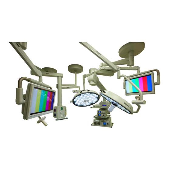
ALL OR'S SHOULD BE CONSIDERED AS
Booms and Lights
FULLY INTEGRATED WITH VIDEO, VOICE
ACTIVATION AND INSTRUMENT CONTROL
Installation and Service Manual
July 2011
1004-400-061 REV YB
www.stryker.com
Table of
Contents
Previous
Page
Next
Page
1
2
3
4
5
Advertisement
Table of Contents
Troubleshooting
Power Supply Box
96
Can Bus Troubleshooting
110
Servicing Booms
114
Need help?
Do you have a question about the Visum 450 and is the answer not in the manual?
Ask a question
Questions and answers
Related Manuals for Stryker Visum 450
Medical Equipment Stryker Visum Operation Manual
Blade led surgical light system (44 pages)
Medical Equipment Stryker Visum 300 Assembly, Operation And Maintenance Instructions
Ceiling-mounted exam light (32 pages)
Medical Equipment Stryker Visum 600 Installation And Service Manual
(149 pages)
Medical Equipment Stryker B3000n Badge Cleaning Manual
(6 pages)
Medical Equipment Stryker ProCuity Bed Series Operation Manual
(84 pages)
Medical Equipment Stryker ProCuity 3009PX-L-300 Operation Manual
(86 pages)
Medical Equipment Stryker SIDNE StrykeCam 2 User Manual
Sidne stryker visum led surgical light & strykecam 2 in-light camera package (396 pages)
Medical Equipment Stryker 1488 Manual
Hd 3-chip pendulum camera with integrated coupler (29 pages)
Medical Equipment Stryker 1115 Operation Manual
Prime series big wheel stretcher (66 pages)
Medical Equipment Stryker 747 Operation Manual
Transport stretcher (427 pages)
Medical Equipment Stryker Secure II 3002 Maintenance Manual
Med-surg bed (276 pages)
Medical Equipment Stryker InTouch FL27 Maintenance Manual
(252 pages)
Medical Equipment Stryker PneumoSure Instructions For Use Manual
High flow insufflator for laparoscopy and vessel harvesting (410 pages)
Medical Equipment Stryker PneumoSure Service Manual
High flow insufflator (76 pages)
Medical Equipment Stryker L10 Instructions For United States Users
Led light source with aim technology (52 pages)
Medical Equipment Stryker Triathlon Tritanium Surgical Manualline
With triathlon cementless beaded pa femoral component (66 pages)
This manual is also suitable for:
Mmp200
Visum 600
Osc400
Oms-200
Osc600
Table of Contents
Save PDF
Print
Rename the bookmark
Delete bookmark?
Delete from my manuals?
Login
Sign In
OR
Sign in with Facebook
Sign in with Google
Upload manual
Upload from disk
Upload from URL


Need help?
Do you have a question about the Visum 450 and is the answer not in the manual?
Questions and answers