
Related Manuals for Stryker stair-pro 6250


Summary of Contents for Stryker stair-pro 6250
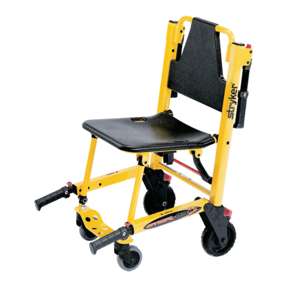
- Page 1 Stair-PRO Stair Chair ® Model 6250/6251/6252 Operations/Maintenance Manual Model 6250 Model 6251 Model 6252 For parts or technical assistance call: 1-800-327-0770 2011/03 6250-001-160 REV E.2 www.stryker.com...
-
Page 3: Table Of Contents
Stryker EMS Return Policy ........ - Page 4 Elastic Oxygen Bottle Holder - 6250-140-000 ........... 6250-001-160 REV E www.stryker.com...
-
Page 5: Symbols And Definitions
Provides special information to make maintenance easier or important instructions clearer. Return To Table of Contents www.stryker.com 6250-001-160 REV E... -
Page 6: Introduction
Maximum load capacity is total weight distributed in accordance to basic human anatomy. Operators must consider the weight of the patient, equipment, and accessories when determining the total load on the product. Stryker reserves the right to change specifications without notice. Return To Table of Contents 6250-001-160 REV E www.stryker.com... -
Page 7: Return To Table Of Contents Www.stryker.com 6250-001-160 Rev E
Optional Lift Handles Release Lever Upper Control Handle Release Cable Chair Fold Stair−TREAD Lock Bar Lock Bar Wheel Lock Lift Handle Release Button Lift Handle Release Button Foot End Front Caster Lift Handles Return To Table of Contents www.stryker.com 6250-001-160 REV E... -
Page 8: Warranty
Stryker, found to be defective. Two (2) year parts. Under this option, Stryker EMS warrants to the original purchaser that non-... -
Page 9: Stryker Ems Return Policy
Claim will be limited in amount to the actual replacement cost. In the event that this information is not received by Stryker within the fifteen (15) day period following the delivery of the merchandise, or the damage was not noted on the delivery receipt at the time of receipt, the customer will be responsible for payment of the original invoice in full. -
Page 10: Summary Of Safety Precautions
® Stair Chair as described in this manual. Use only Stryker approved parts and maintenance procedures. Using unapproved parts and procedures could cause unpredictable operation and/or injury and will void the product warranty. • Casters are not suitable for all surfaces. Caution should be used at all times. -
Page 11: Setup Procedures
Do not modify the Stair-PRO Stair Chair. Modifying the chair can cause unpredictable operation resulting in injury to the ® patient or operator. Modifying the chair will also void its warranty. Return To Table of Contents www.stryker.com 6250-001-160 REV E... -
Page 12: Operation Guide
Stair-TREAD™ system, ensure the belts are clean and dry before transporting the patient. • To avoid injury to the operators and/or the patient, operators should never attempt to transport patient loads greater than what they can safely lift. Return To Table of Contents 6250-001-160 REV E www.stryker.com... -
Page 13: Unfolding The Chair
Verify the lock is engaged by pulling up on the seat. If the lock is properly engaged, the chair will not fold. WARNING An unlocked chair can fold during use, causing injury to the patient or operator. Always make sure the chair is locked in the unfolded position before use. Return To Table of Contents www.stryker.com 6250-001-160 REV E... -
Page 14: Folding The Chair
Note: On models 6251 and 6252, rotate the front casters so they do not interfere with folding the chair. WARNING An unlocked chair can fold during use, causing injury to the patient or operator. Always make sure the chair is locked in the unfolded position before use. Return To Table of Contents 6250-001-160 REV E www.stryker.com... -
Page 15: Transferring The Patient To The Stair-Pro ® Stair Chair
Use all the restraints to secure the patient on the chair (page 16). Disengage the wheel locks before transporting. WARNING The Stair-PRO® is not recommended for use with suspected cervical, spinal, or fracture injuries. Return To Table of Contents www.stryker.com 6250-001-160 REV E... -
Page 16: Using Restraint Straps
To avoid damage to the buckles and straps, keep the restraint straps buckled when the chair is not being used with a patient. When attaching the restraint straps to the chair, remember the attachment points must provide strong anchorage and proper restraint position while not interfering with equipment and accessories. Return To Table of Contents 6250-001-160 REV E www.stryker.com... -
Page 17: Return To Table Of Contents
Figure 7 - Lengthen strap as necessary Figure 5 - Insert the end through the loop Figure 8 - Buckle strap Figure 6 - Pull the strap tight Figure 9 - Tighten strap securely Return To Table of Contents www.stryker.com 6250-001-160 REV E... -
Page 18: Return To Table Of Contents
Pull until the “D” ring rests against the foot rest tube. Attach the final “male” end clip on the strap. Figure 10-18 - Attaching the leg strap Return To Table of Contents 6250-001-160 REV E www.stryker.com... -
Page 19: Proper Lifting Techniques
• Keep your back straight. • Coordinate your movements with your partner and lift with your legs. • Avoid twisting. • Always operate the Stair-PRO ® Stair Chair as described in this manual. Return To Table of Contents www.stryker.com 6250-001-160 REV E... -
Page 20: Transporting The Patient On Flat Surfaces
Do not push the Model 6252 with the upper control handle in the fully extended position. Pushing the chair with the handle in the fully extended position may cause the chair to tip when obstacles are encountered. Return To Table of Contents 6250-001-160 REV E www.stryker.com... -
Page 21: Transporting The Patient Down Stairs
Both operators - simultaneously lift the chair, using the head and foot end lift handles and following the proper lifting techniques (see page 19). Carry the chair slowly down the stairs, avoiding any obstructions. Return To Table of Contents www.stryker.com 6250-001-160 REV E... -
Page 22: Return To Table Of Contents
Operators face each other while descending the stairs. Head end operator - Tilt the chair back just far enough to allow the Stair-TREAD™ system to contact the floor. Figure 28 - Tilt the chair Return To Table of Contents 6250-001-160 REV E www.stryker.com... -
Page 23: Return To Table Of Contents
Figure 32 - Bottom of stairs the upper control handle while the foot end operator provides slight upward pressure to tilt the chair back and engage the Stair-TREAD™ system. Return To Table of Contents www.stryker.com 6250-001-160 REV E... -
Page 24: Transporting The Patient Up Stairs
(see page 19). Carry the chair slowly up the stairs, avoiding any obstructions. Figure 35 - Transporting up the stairs Figure 36 - Transporting up the stairs Return To Table of Contents 6250-001-160 REV E www.stryker.com... -
Page 25: Operating The Wheel Locks
5” diameter (Model 6252) or a 6” diameter (Models 6250/6251) could compromise the holding ability of the wheel lock, possibly resulting in injury to the patient or operator and/or damage to the chair or other equipment. Return To Table of Contents www.stryker.com 6250-001-160 REV E... -
Page 26: Adjusting The Wheel Locking Force
Test the pedal locking force and verify that it holds properly before returning the chair to service. Note: If, after adjustment, the pedal still does not hold the wheel properly, replace the wheel. Return To Table of Contents 6250-001-160 REV E www.stryker.com... -
Page 27: Operating The Optional Locking Rear Lift Handles
To lower the handles: Lift up on the handle, pull the red trigger toward you with your thumb and fold the handle down against the chair frame. Return To Table of Contents www.stryker.com 6250-001-160 REV E... -
Page 28: Using The Optional Head Support (Model 6252 Only)
Wrap around the patient’s head, and overlap the straps to the desired tightness to secure. When not in use, these straps can be wrapped back around the handle and attached to the back of the support. Return To Table of Contents 6250-001-160 REV E www.stryker.com... -
Page 29: Using Additional Assistance
UP STAIRS Two Operators Operator Operator Operator Operator Two Operators One Helper Operator Two Operators Two Helpers Operator Helper Operator Helper Helper Helper Two Operators Three Helpers Operator Helper Operator Helper Return To Table of Contents www.stryker.com 6250-001-160 REV E... -
Page 30: Cleaning
WASHING PROCEDURE • Follow the cleaning solution manufacturer’s dilution recommendations exactly. • The preferred method Stryker Medical recommends for power washing stair chairs is with the standard hospital surgical cart washer or hand held wand unit. WASHING LIMITATIONS WARNING Use any appropriate personal safety equipment (goggles, respirator, etc.) to avoid the risk of inhaling contagion. -
Page 31: Return To Table Of Contents
• SOME CLEANING PRODUCTS ARE CORROSIVE IN NATURE AND MAY CAUSE DAMAGE TO THE PRODUCT IF USED IMPROPERLY. If the products described above are used to clean Stryker patient care equipment, measures must be taken to insure the chairs are wiped with a cloth soaked in clean water and thoroughly dried following cleaning. -
Page 32: Preventative Maintenance
(6252) Note: Keep up to date maintenance records using the Maintenance Record form on page Parts, Service or Technical Assistance Contact Stryker Customer Service at 1-800-327-0770 or Stryker Medical 3800 E. Centre Ave. Portage, MI 49002 ATTN: Customer Service... -
Page 33: Maintenance Record
Maintenance Record Date Maintenance Operation Performed Hours Return To Table of Contents www.stryker.com 6250-001-160 REV E... -
Page 34: Training Record
Training Record Training Date Training Method Trainee Name Basic Refresher Owner’s Manual, In-Service, Training Update Formal Class, Etc. Return To Table of Contents 6250-001-160 REV E www.stryker.com... -
Page 35: Quick Replacement Part List
The parts and accessories listed on this page are all currently available for purchase. Some of the parts identified on the assembly drawing parts in this manual may not be individually available for purchase. Please call Stryker Customer Service (800)-327-0770 for availability and pricing. -
Page 36: Service Information
Insert both ends of the top strap through the loops in the back section. Thread the end of the strap through the buckle and pull it tight. Thread the end of the bottom strap through the buckle and pull it tight. Return To Table of Contents 6250-001-160 REV E www.stryker.com... -
Page 37: Track Belt Replacement (For Model 6252)
Using a 1/2” wrench and a 3/16” hex key, remove the button head cap screw, nut, spacers and wheel from the frame on the same side as the parts removed in step one. Figure 48 - Remove the wheel assembly Return To Table of Contents www.stryker.com 6250-001-160 REV E... -
Page 38: Return To Table Of Contents
Figure 50 - Remove the rollers Remove the belts by threading them through the wheel support plate on the side where the parts were removed. Figure 51 - Remove the worn belts Return To Table of Contents 6250-001-160 REV E www.stryker.com... -
Page 39: Return To Table Of Contents
The gap between the belt and the track frame should measure between 3/8” and 1” as shown in Figure 54. 10. Spin the belts to verify they roll freely. Figure 54 - Proper belt tension Return To Table of Contents www.stryker.com 6250-001-160 REV E... -
Page 40: Track Belt Reconditioning (For Model 6252)
4. For a start/end point reference while sanding, use a permanent marker to color a tooth on the belt. Figure 57 - Mark a belt tooth for reference Return To Table of Contents 6250-001-160 REV E www.stryker.com... -
Page 41: Return To Table Of Contents
The gap between the belt and the track frame should measure between 3/8” and 1” as shown in Figure 61. 10. Spin the belts to verify they roll freely. Figure 61 - Proper belt tension Return To Table of Contents www.stryker.com 6250-001-160 REV E... -
Page 42: Rear Wheel Replacement
Discard the cap screw and nut. Use the new fasteners provided to attach the new wheel to the frame. Repeat for the other wheel, if necessary. Figure 63 - Remove the wheel assembly Return To Table of Contents 6250-001-160 REV E www.stryker.com... -
Page 43: Upper Control Handle Cable Replacement (For Model 6252)
Repeat steps 2-4 for the other end of the cable. Figure 65 - Remove one side of the cable Figure 67 - Attach one side of the new cable Figure 66 - Place the washer on the new cable Return To Table of Contents www.stryker.com 6250-001-160 REV E... -
Page 44: Chair Assembly
Chair Assembly 6250-001-005 Rev T (Reference Only) Return To Table of Contents 6250-001-160 REV E www.stryker.com... -
Page 45: Www.stryker.com 6250-001-160 Rev E
Chair Assembly 6250 6251 6252 Return To Table of Contents www.stryker.com 6250-001-160 REV E... -
Page 46: Return To Table Of Contents
Chair Assembly Return To Table of Contents 6250-001-160 REV E www.stryker.com... -
Page 47: Return To Table Of Contents
Lock Mechanism Assy. (page 6250-001-098 Pivot Spacer 6250-001-111 Flip-Up Handle Pivot Spacer 6250-001-140 Label, Stair-PRO ® 6082-090-042 Label, 8” Stryker 0011-209-000 Washer 0004-517-000 Socket Head Cap Screw 0011-159-000 Washer MODEL 6250 - 6250-001-010 Rev B (Reference Only) Item Part No. -
Page 48: Return To Table Of Contents
Part Name Qty. 6252-001-012 Upper Extension Handle 6252 I.V. Bag Clip Option - 6252-025-000 (Rev A) Item Part No. Part Name Qty. 6252-001-212 I.V. Clip Upper Extension Handle 6252-001-153 I.V. Strap Return To Table of Contents 6250-001-160 REV E www.stryker.com... -
Page 49: 6250/6251 Main Frame Assembly
6250-001-102 Outer Wheel Supt. Spacer 6250-001-103 Inner Wheel Supt. Spacer 6250-001-104 Wheel Support 6250-001-118 Lock Retaining Spring 6250-001-131 Spring 6250-001-132 Seat Spacer 6250-001-134 Rivet Back Plate 0025-079-000 Blind Rivet 0011-209-000 Washer Return To Table of Contents www.stryker.com 6250-001-160 REV E... -
Page 50: 6252 Main Frame Assembly
6252 Main Frame Assembly 6252-001-011 Rev J (Reference Only) Return To Table of Contents 6250-001-160 REV E www.stryker.com... -
Page 51: Return To Table Of Contents
6252 Main Frame Assembly Return To Table of Contents www.stryker.com 6250-001-160 REV E... -
Page 52: Return To Table Of Contents
Wheel Support 6252-001-106 Track Spacer Pivot 6252-001-113 Track Tube Spacer 6252-001-114 5” Wheel 6252-001-120 Track Sleeve Spacer 0004-028-000 Socket Head Cap Screw 0004-204-000 Button Head Cap Screw 0011-064-000 Washer 6250-001-124 Flange Bearing Return To Table of Contents 6250-001-160 REV E www.stryker.com... -
Page 53: Upper Control Handle Assembly - 6252-001-012
Upper Control Handle Assembly - 6252-001-012 Rev B Item Part No. Part Name Qty. 0025-133-000 Blind Rivet 6250-001-085 Internal Slide Bushing 6250-001-087 Outer Extension Handle Bushing 6252-001-090 Upper Internal Handle 6252-001-145 Handle Reinforcer Return To Table of Contents www.stryker.com 6250-001-160 REV E... -
Page 54: 6252 Track Frame Assembly, Standard Belt
6252 Track Frame Assembly, Standard Belt 6252-001-013 Rev E (Reference Only) Return To Table of Contents 6250-001-160 REV E www.stryker.com... -
Page 55: Return To Table Of Contents
Track Belt Roller Spacer 6252-001-085 Track Belt 6252-001-102 Wheel Support Stamping 6252-001-103 Wheel Support Stamping 6252-001-105 Lock Mechanism Cross Bar 6252-001-110 Latch 6252-001-111 Latch 6252-001-112 Spring 6252-001-121 Lock Pivot Internal Spacer Return To Table of Contents www.stryker.com 6250-001-160 REV E... -
Page 56: Internal Latch Assembly
6252-001-014 Rev B (Reference Only) Item Part No. Part Name Qty. 0014-098-000 Washer 0038-506-000 Compression Spring 6252-001-097 Latch Retainer Block 6252-001-098 Latch Release Slide 6252-001-099 Track Latch Lock 6252-001-101 Single Spring Return To Table of Contents 6250-001-160 REV E www.stryker.com... -
Page 57: Internal Latch Assembly
6252-001-015 Rev B (Reference Only) Item Part No. Part Name Qty. 0014-098-000 Washer 0038-506-000 Compression Spring 6252-001-097 Latch Retainer Block 6252-001-098 Latch Release Slide 6252-001-099 Track Latch Lock 6252-001-100 Single Spring Return To Table of Contents www.stryker.com 6250-001-160 REV E... -
Page 58: Cable And Pin Assembly - 6252-001-016
Cable and Pin Assembly - 6252-001-016 Rev B Item Part No. Part Name Qty. 0038-507-000 Compression Spring 6252-001-115 Pull Pin 6252-001-116 Pull Pin Bolt 6252-001-119 Cable Return To Table of Contents 6250-001-160 REV E www.stryker.com... -
Page 59: Wheel Assembly - 6060-002-010
Wheel Assembly - 6060-002-010 Rev B Item Part No. Part Name Qty. 6060-002-045 6” Molded Wheel 6060-002-046 Bearing Spacer 0081-226-000 Bearing 0715-001-255 Wheel Bushing Return To Table of Contents www.stryker.com 6250-001-160 REV E... -
Page 60: 6250/6251/6252 Locking Flip-Up Handle Option
6250-031-000 Rev E (Reference Only) Item Part No. Part Name Qty. 0004-204-000 Button Head Cap Screw 0016-028-000 Nylock Nut 6250-001-111 Flip-Up Handle Pivot Spacer 6250-001-113 Flip-Up Handle Trigger 6250-001-114 Single Spring Return To Table of Contents 6250-001-160 REV E www.stryker.com... -
Page 61: 6250 Foot Tube Assembly - 6250-001-012
6250 Foot Tube Assembly - 6250-001-012 Rev A Item Part No. Part Name Qty. 6250-001-090 Foot Section End Cap 6250-001-091 Foot Section Tube 6250-001-096 Foot/Seat Section End Cap Return To Table of Contents www.stryker.com 6250-001-160 REV E... -
Page 62: 6251/6252 Foot Support Assembly - 6251-001-012
6251/6252 Foot Support Assembly - 6251-001-012 Rev A Item Part No. Part Name Qty. 0016-064-000 Nylock Hex Nut 6250-001-090 Foot Section End Cap 6250-001-096 Foot/Seat Section End Cap 6251-001-050 Foot Section Weldment 6251-001-083 Caster Return To Table of Contents 6250-001-160 REV E www.stryker.com... -
Page 63: 6250/6251/6252 Standard Lower Lift Handle/No Foot Rest
No Foot Rest Option - 6252-028-000 (Rev C) Item Part No. Part Name Qty. Item Part No. Part Name Qty. 6250-001-014 Extension Handle, Right 6250-001-098 Pivot Spacer 6250-001-015 Extension Handle, Left 6250-001-129 Pivot Spacer 6250-001-133 Spacer Return To Table of Contents www.stryker.com 6250-001-160 REV E... -
Page 64: Return To Table Of Contents
6250-025-000 Rev C (Reference Only) Item Part No. Part Name Qty. 6250-003-014 Extension Extended Handle, Right 6250-003-015 Extension Extended Handle, Left 6250-003-129 Pivot Spacer 6250-003-133 Spacer, Extension Handle Locator 6250-003-134 Spacer, Extension Handle Locator Return To Table of Contents 6250-001-160 REV E www.stryker.com... -
Page 65: Extension Handle Assembly, Right - 6250-001-014
Internal Extension Handle 6250-001-082 Pivot Bracket 6250-001-083 Lock Pin 6250-001-085 Internal Slide Bushing 6250-001-086 Outer End Cap 6250-001-087 Outer Bushing 6250-001-089 Hand Grip 6250-001-112 Dead Stop 6250-001-121 Extension Outer Handle, Right Return To Table of Contents www.stryker.com 6250-001-160 REV E... -
Page 66: Extension Handle Assembly, Left - 6250-001-015
Internal Extension Handle 6250-001-082 Pivot Bracket 6250-001-083 Lock Pin 6250-001-085 Internal Slide Bushing 6250-001-086 Outer End Cap 6250-001-087 Outer Bushing 6250-001-089 Hand Grip 6250-001-112 Dead Stop 6250-001-122 Extension Outer Handle, Left Return To Table of Contents 6250-001-160 REV E www.stryker.com... -
Page 67: 6251/6252 Foot Rest Option
6251/6252 Foot Rest Option 6252-027-000 Rev B (Reference Only) Item Part No. Part Name Qty. 6250-003-098 Pivot Spacer 6252-001-017 Foot Support Assembly Return To Table of Contents www.stryker.com 6250-001-160 REV E... -
Page 68: 6252 Extended Handle/No Foot Rest Option
6252 Extended Handle/No Foot Rest Option 6252-030-000 Rev C (Reference Only) Item Part No. Part Name Qty. 6250-003-098 Pivot Spacer Return To Table of Contents 6250-001-160 REV E www.stryker.com... -
Page 69: 6252 Extended Handle/Foot Rest Option
6252 Extended Handle/Foot Rest Option 6252-029-000 Rev B (Reference Only) Item Part No. Part Name Qty. 6250-003-099 Pivot Spacer 6252-001-017 Foot Support Assembly Return To Table of Contents www.stryker.com 6250-001-160 REV E... -
Page 70: Seat Section Assembly - 6250-001-013
Seat Section Assembly - 6250-001-013 Rev B Item Part No. Part Name Qty. 0025-120-000 Rivet 6250-001-165 Clip 6250-001-050 Seat Frame Weldment 6250-001-096 Foot/Seat Section End Cap Return To Table of Contents 6250-001-160 REV E www.stryker.com... -
Page 71: Flip-Up Handle Assembly - 6250-001-016
Flip-Up Handle Assembly - 6250-001-016 Rev A Item Part No. Part Name Qty. 0025-132-000 Blind Rivet 6250-001-052 Flip-Up Handle Weldment 6250-001-089 Hand Grip Return To Table of Contents www.stryker.com 6250-001-160 REV E... -
Page 72: Lock Mechanism Assembly - 6250-001-017
Lock Mechanism Assembly - 6250-001-017 Rev B Item Part No. Part Name Qty. 0004-515-000 Button Head Cap Screw 6250-001-094 Strut 6250-001-095 Cross Bar 6250-001-124 Flange Bearing Return To Table of Contents 6250-001-160 REV E www.stryker.com... -
Page 73: 6250/6251/6252 Vinyl Seat Option
6250/6251/6252 Vinyl Seat Option 6250-020-000 Rev E (Reference Only) Item Part No. Part Name Qty. 0004-517-000 Socket Head Cap Screw 0011-064-000 Washer 0011-209-000 Washer 0016-028-000 Nylock Hex Nut 6250-001-098 Pivot Spacer 6250-001-135 Vinyl Seat Return To Table of Contents www.stryker.com 6250-001-160 REV E... -
Page 74: 6250/6251/6252 Abs Seat Option
Qty. 0004-517-000 Socket Head Cap Screw 0011-064-000 Washer 0011-209-000 Washer 0016-028-000 Nylock Hex Nut 0025-172-000 Blind Rivet 6250-001-099 Seat Support Bracket 6250-001-115 Plastic Seat 6250-001-116 Plastic Back Rest 6250-001-128 Pivot Spacer Return To Table of Contents 6250-001-160 REV E www.stryker.com... -
Page 75: Seat And Back Rest Options
ABS SEAT - 6250-001-115 (Rev C) ABS SEAT OPTION - 6250-021-000 (Rev D) ABS BACKREST - 6250-001-116 (Rev C) VINYL SEAT - 6250-001-135 (Rev B) VINYL SEAT OPTION - 6250-020-000 (Rev E) Return To Table of Contents www.stryker.com 6250-001-160 REV E... -
Page 76: 6252 Head Support Options
Head Support Option - 6250-040-000 (Rev B) Item Part No. Part Name Qty. 6252-001-122 Head Support Vinyl Head Support Option - 6250-041-000 (Rev B) Item Part No. Part Name Qty. 6252-001-140 Vinyl Head Support Return To Table of Contents 6250-001-160 REV E www.stryker.com... -
Page 77: Restraint Set, Non-Absorbent/Metal Buckles Option
6250-162-000 Rev B (Reference Only) 25.25” 55” Fully Extended 54” Restraint Strap Set - 6250-001-021 (Rev B) Item Part No. Part Name Qty. 6060-160-044 Lap Belt Assembly 6250-001-127 Ankle Restraint Strap 6250-001-163 Restraint Buckle Return To Table of Contents www.stryker.com 6250-001-160 REV E... -
Page 78: Restraint Set, Polypropylene/Plastic Buckles Option
Restraint Set, Polypropylene/Plastic Buckles Option 6250-160-000 Rev D (Reference Only) 15” 56” 15” 56” 54” Restraint Strap Set - 6250-001-022 (Rev A) Item Part No. Part Name Qty. 6250-001-018 Restraint Strap Set 6250-001-163 Restraint Buckle Return To Table of Contents 6250-001-160 REV E www.stryker.com... -
Page 79: Optional Vinyl Head Support - 6252-001-140
Optional Vinyl Head Support - 6252-001-140 Rev B 10.00” 36.25” Return To Table of Contents www.stryker.com 6250-001-160 REV E... -
Page 80: Elastic Oxygen Bottle Holder - 6250-140-000
Elastic Oxygen Bottle Holder - 6250-140-000 Rev A Return To Table of Contents 6250-001-160 REV E www.stryker.com... - Page 82 United States Stryker Medical 3800 E. Centre Ave., Portage, Michigan USA 49002 European Representative Stryker France ZAC Satolas Green Pusignan Av. De Satolas Green 69881 MEYZIEU Cedex France 2011/03 6250-001-160 REV E www.stryker.com...
Need help?
Do you have a question about the stair-pro 6250 and is the answer not in the manual?
Questions and answers