
Related Manuals for Thermo Scientific DensityPRO-T Series


Summary of Contents for Thermo Scientific DensityPRO-T Series
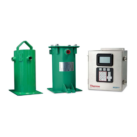
- Page 1 DensityPRO Measurement Systems DensityPRO & DensityPRO-T DensityPRO NAI & DensityPRO NAI+ Gamma Density Measurement Systems User Manual PN 1-0702-016...
- Page 3 DensityPRO Measurement Systems DensityPRO & DensityPRO-T DensityPRO NAI & DensityPRO NAI+ Gamma Density Measurement Systems User Manual PN 1-0702-016...
- Page 5 However, we cannot be responsible for errors, omissions, or any loss of data as the result of errors or omissions. Thermo Scientific reserves the right to make changes to the manual or improvements to the product at any time without notice.
- Page 6 This page intentionally left blank...
-
Page 7: Revision History
Date Comments 08-2015 Initial release per ERO 8698 ECO 9079 - Added handling of calibration and 02-2017 standardization in Primary Measurement Type for Main CPU version >= 3.600 08-2019 Add Security Consideration per ECO 9808 Thermo Scientific DensityPRO User Manual... - Page 8 This page intentionally left blank...
-
Page 9: Table Of Contents
Totalizers & Batch Control ..................1-6 Output Signals ......................1-6 Additional Documents ....................1-6 Chapter 2 EZ Cal II Overview ......................2-1 Features .......................... 2-1 Startup ..........................2-2 The Measurement Display ..................... 2-2 The Setup Wizard ......................2-2 Thermo Scientific DensityPRO User Manual A-ix... - Page 10 System Control ....................... 4-4 Configuration ......................4-5 System Status ........................ 4-6 Mode/Fault Alarm Setup ....................4-7 System Tab ........................ 4-9 System Status Tab ....................4-12 Application Tabs ...................... 4-12 Commands ........................4-14 Common Action ....................... 4-14 DensityPRO User Manual Thermo Scientific...
- Page 11 Density Setup ...................... 4-44 Input Configuration Setup ................... 4-49 Temperature Compensation Setup ..............4-52 Additional Measurement Setup ................4-54 General Setup ..................... 4-57 Standardization ......................4-58 Using as a Default Calibration Value ..............4-58 Thermo Scientific DensityPRO User Manual A-xi...
- Page 12 Additional Measurements ..................C-7 Slurry Material ....................... C-8 Slurry Density Calculation ..................C-8 Additional Measurements ................... C-14 Proppant ........................C-17 In Situ Calculation ....................C-18 Emulsion Material ......................C-19 Emulsion Density Calculation .................. C-19 Additional Measurements ................... C-25 DensityPRO User Manual Thermo Scientific...
- Page 13 Solution Material ......................C-25 Solution Calculation ....................C-26 Additional Measurements ................... C-31 Temperature Compensated Density ................C-32 Temperature Compensated Calculation ..............C-32 Standardization with Temperature Compensation ..........C-33 Temperature Compensation during Calibration ............C-33 Thermo Scientific DensityPRO User Manual A-xiii...
- Page 14 This page intentionally left blank DensityPRO User Manual Thermo Scientific...
-
Page 15: Safety Information & Guidelines
Caution: Using this equipment in a manner not specified by Thermo Scientific may impair the protective features provided by the product, leading to equipment damage and/or personnel injury. Thermo Scientific DensityPRO User Manual... -
Page 16: Warnings, Cautions & Notes
Note: Notes emphasize important or essential information or a statement of company policy regarding an operating procedure, practice, condition, etc. Warning ThermoFisher Scientific strongly recommends changing Security passwords before first use/login on this equipment. Consideration DensityPRO User Manual Thermo Scientific... -
Page 17: New Functionality For Cpu Firmware Version 3.600 And Above
Caution: Using this equipment in a manner not specified by Thermo Scientific may impair the product, leading to equipment malfunction. 1. New Functionality for CPU Firmware Version 3.600 and above. NOTE: Please read the notes below before upgrading from CPU firmware ≤... - Page 18 Measurement type and NOT in "g/cc" as shown on the User Interfaces (UI). The user must update items 3-8 as necessary to reflect correct STD/CAL unit on the Standardization and Calibration page of the UI. DensityPRO User Manual xviii Thermo Scientific...
- Page 19 Use previously saved configuration file on your laptop Manually re-enter the process variable units that you noted earlier Upload CFG from Gauge using EZ CAL II and save the file to your laptop for future reference Thermo Scientific DensityPRO User Manual...
-
Page 20: Quick Setup
It is only a repeatable radiation condition. The first point calibration is associated with the standardization through the first point calibration density and a CAL/STD ratio where the ratio is equal to the signal at the calibration density divided by the standardization signal. A-xx Thermo Scientific DensityPRO User Manual... -
Page 21: Calibration
The slope can be set using the second point calibration or entered directly. If the gauge is standardized on water or on process, the standardization serves as the first calibration point. DensityPRO User Manual Thermo Scientific... - Page 22 Quick Setup This page intentionally left blank A-xxii Thermo Scientific DensityPRO User Manual...
-
Page 23: Chapter 1 Product Overview
DensityPRO will refer to the complete family of gauges, unless otherwise specified. The Thermo Scientific DensityPRO family of gauges has been designed to provide reliable, accurate process material density measurements for a wide variety of challenging applications. The instrument is mounted outside of the process vessel and never contacts the process material. -
Page 24: Function
(density) can be viewed on the display and on the EZ Cal II software. Display The display on the DensityPRO units provides measurement data to the user. Display Background Figure 1-2. Measurement Data Display DensityPRO User Manual Thermo Scientific... -
Page 25: Local Display (Integrated Unit)
The option to change the password mode entry. The option to display user interface menu text in the following languages: English Chinese (available in future releases) Portuguese (available in future releases) Spanish (available in future releases) Thermo Scientific DensityPRO User Manual... -
Page 26: Inputs & Outputs
Product Overview Function 2. When the user first starts up the system, the display informs the user that the system is booting. THERMO SCIENTIFIC MS2011 SYSTEM IS BOOTING Figure 1-4. Boot Screen 3. When navigating the menus, the keypad has the following functions: a. -
Page 27: Features
Additional menu groups contain fields in which you can enter specialized parameters and commands, allowing you to customize the gauge for a wide variety of applications. Note: The setup wizard is only available when using the PC-based EZ Cal II software. Thermo Scientific DensityPRO User Manual... -
Page 28: Instantaneous Response
In addition to this guide, the following documents must be read and understood by all Additional persons installing, using, or maintaining this equipment: Documents – DensityPRO NAI installation guide (P/N 1-0702-015) – DensityPRO installation guide (P/N 1-0702-144) – Gamma Radiation Safety (P/N 717904) DensityPRO User Manual Thermo Scientific... -
Page 29: Ez Cal Ii Overview
An option to upload configuration from a gauge to the PC and save it to a file. – An option to download a file configuration from a PC to the gauge. – The option to enter a special password for cold and warm start operation. Thermo Scientific DensityPRO User Manual... -
Page 30: Startup
The setup wizard provides you with a step-by-step procedure for entering the data The Setup required for gauge operation. To start the wizard, open the EZ Cal II software and Wizard click on the small blue wizard’s cap on the task bar, underneath the View menu option. DensityPRO User Manual Thermo Scientific... -
Page 31: Chapter 3 Startup & The Setup Wizard
Edit screens run in a read mode and a write mode. with the Edit Read mode displays data to the user. The screen continues to display up-to-date Screens information. Pressing the F2 button will open the screen to write mode. Thermo Scientific DensityPRO User Manual... -
Page 32: Startup & The Setup Wizard
DensityPRO NAI+ keypad display screens can be found in Appendix A, Keypad Display Menu Tree of DensityPRO Gauges. Each section of instruction on the EZ Cal II software will provide the location of the corresponding keypad display screens in Appendix A. DensityPRO User Manual Thermo Scientific... -
Page 33: Upload / Download Configuration
Download File to Gauge button. To delete a file from the list, highlight the file and click the Delete button. This will delete the file from the list but not from the computer. Thermo Scientific DensityPRO User Manual... -
Page 34: Ez Cal Ii Control Buttons
Technician Mode – The local user can configure a small sub-set of the database within the gauge via the front panel menu system on the RBP. Remote write access is also available to a small subset of the gauge database so that calibration and standardization can be performed. DensityPRO User Manual Thermo Scientific... - Page 35 Technician Mode Count – Invalid Password Count The following values shall be available for editing purpose when the gauge is in engineering mode. – Engineering Password – Technician Password – Operator Password – Engineering Mode Count Thermo Scientific DensityPRO User Manual...
-
Page 36: Password Entry/Validation
To keep passwords hidden by having them display as asterisks onscreen at key-in, enable the Display Password Mode field. Disabling this field will show the information entered. – Enter the password into the User Password Entry textbox to enter Engineer mode. DensityPRO User Manual Thermo Scientific... -
Page 37: System Timeout
Begin the density setup using the setup wizard. To start the wizard, click on the small The Setup blue wizard’s cap on the task bar, underneath the View menu option. Wizard Figure 3-3. Detector and Application Type Selection Thermo Scientific DensityPRO User Manual... - Page 38 Oilfield – An application expressly designed for the DensityPRO NAI-O gauges used in the hydraulic fracturing, or fracking, industry, this configuration is very similar to the fracking preload configuration found in our previous products. DensityPRO User Manual Thermo Scientific...
- Page 39 Only the parameters related to the selected wizard type will be uploaded. d. Click Download File to Gauge. 6. Click the Next button to proceed to the next screen. Figure 3-5. Wizard Type Selection 7. Select Density Setup. Thermo Scientific DensityPRO User Manual...
- Page 40 The available options are slurry, solution, single-phase or emulsion. After selecting the material type, click the Next button to move to the next screen. The options on this screen are dependent on the material type selected. DensityPRO User Manual Thermo Scientific...
- Page 41 Note: If you want to measure the overall density of the process material only, you can select single-phase, regardless of the material’s makeup. 9. After making the appropriate selections on this screen, click the Next button to proceed to the Gravity & Attenuation screen. Thermo Scientific DensityPRO User Manual 3-11...
- Page 42 Solute Attenuation (cm Single Phase Carrier Density (g/cc) Carrier Attenuation (cm Emulsion Fluid 1 Density (g/cc) Fluid 2Density (g/cc) Fluid 1 Attenuation (cm Fluid 2 Attenuation (cm DensityPRO User Manual Thermo Scientific...
- Page 43 13. Enter a unit of measure for the pipe, as well as the pipe’s inside diameter. 14. Select a unit of measure from the Density Unit dropdown. 15. Click Next to proceed. Figure 3-9. Polynomial Coefficients Thermo Scientific DensityPRO User Manual 3-13...
-
Page 44: Temperature Compensation
Temperature compensation is used to compensate for the effects of process material temperature variations. Gauges configured with the temperature compensation option will display the process density corrected back to the customer-supplied reference temperature. DensityPRO User Manual Thermo Scientific... - Page 45 The default value is 20º. Temperature at 4 mA and 20 mA – Input the temperatures for both 4 mA and 20 mA in these textboxes. 2. Click the Next button to proceed. Thermo Scientific DensityPRO User Manual 3-15...
- Page 46 Figure 3-12. Polynomial Equations, Reference Temperature & Offset Correction Figure 3-13. Temperature Compensation Coefficients 3. Once the temperature compensation setup is complete, save the file, if desired, and click the Next button to return to the Wizard Type Selection Screen. DensityPRO User Manual Thermo Scientific...
-
Page 47: Standardization
Caution: The Bypass option should only be used if recommended by a Thermo Fisher technical support specialist. This option inserts a value of one for the standardization count, which under some circumstances can have detrimental effects. Thermo Scientific DensityPRO User Manual 3-17... - Page 48 3. Once the standardization parameters have been completed, click the Next button to finish standardization. 4. Save the file, if desired, and click the Next button once more to reach the Wizard Type Selection Screen. DensityPRO User Manual Thermo Scientific...
-
Page 49: Gauge Calibration
Again, the sample time should be based on process conditions. Typical calibration sample times run between 300 and 900 seconds. 2. Click the Next button to move to the Remaining Time Screen. Thermo Scientific DensityPRO User Manual 3-19... - Page 50 10. Save the file to the computer or save the file to the computer and download it to the DensityPRO gauge. Note: To exit the Setup Wizard without saving the input data, click the Cancel button. DensityPRO User Manual Thermo Scientific...
- Page 51 Startup & the Setup Wizard The Setup Wizard Figure 3-18. Calibration Point Data, Polynomial Figure 3-19. Calibration Point Data, Breakpoint Table Thermo Scientific DensityPRO User Manual 3-21...
- Page 52 Wizard. Once Detector 1 has been configured for a density application and saved, there are additional parameters that can be programmed from the EZ Cal II software. See the section regarding Application for further information. DensityPRO User Manual Thermo Scientific...
-
Page 53: Chapter 4 Operation
Com A / Com B or Com B). (RS232) To configure the Com A and Com B ports, select Communication Setup from the EZ Cal II menu tree. Figure 4-1. Communication Setup, Com A / Com B Thermo Scientific DensityPRO User Manual... - Page 54 Operation Communication Setup The default communication settings for the RS232 (Com A and Com B) ports of the gauge and for the Thermo Scientific EZ Cal II are: – Unit ID: – Baud Rate: 9600 – Parity: None – Data Bits: 8 –...
-
Page 55: Rs485
13. Enable or Disable the Ethernet port. 14. Configure the Ethernet IP address, Subnet Mask, and Ethernet IP Gateway. 15. For Modbus using TCP/IP, enter the Modbus encapsulated port number and IP port number in the indicated textboxes. Thermo Scientific DensityPRO User Manual... -
Page 56: Usb Port
16. Select the Floating Format, either Normal or Reversed. This selection determines the order in which bytes and words will be sent. 17. The MAC address should only be configured or changed by Thermo Scientific technical support personnel. Note: For help in establishing the correct information to input onto this screen, please see your system administrator. -
Page 57: Configuration
Note: At this time, it is strongly recommended that configuration information be saved to your computer. If the work has been completed off-line, connect to the density gauge via one of the serial ports and upload the configuration file to the gauge. Thermo Scientific DensityPRO User Manual... -
Page 58: System Status
The only action the user may take on this screen dictates how the data will be viewed. 1. To capture new, updated information, click the Refresh button. 2. To have the information constantly updating on the screen, check the Auto Refresh checkbox. 3. To exit the screen, click the Cancel button. DensityPRO User Manual Thermo Scientific... -
Page 59: Mode/Fault Alarm Setup
– Current Output C Once an output source has been selected, an alarm action can be selected on either the Current Output Relay Outputs screens. For further information on these screens, see these respective sections. Thermo Scientific DensityPRO User Manual... - Page 60 Operation Mode/Fault Alarm Setup Found on System Tab Found on Relay Output Screen Found on Application Tab Found on Current Output Screen Figure 4-5. Alarm Configuration Map DensityPRO User Manual Thermo Scientific...
-
Page 61: System Tab
The alarm is triggered when any of the following actions occur. Diagnostic error: ii. An Input Scan Error occurs and the gauge has a problem reading any of the following devices: Analog inputs Thermo Scientific DensityPRO User Manual... - Page 62 The alarm is triggered when the current output A value is below the minimum value set by the Namur Standard. b. The alarm is cleared when the current output A value is above the minimum value set by the Namur Standard. DensityPRO User Manual Thermo Scientific...
- Page 63 The alarm is triggered when the current output C value is above the maximum value set by the Namur Standard. b. The alarm is cleared when the current output C value is below the maximum value set by the Namur Standard. Thermo Scientific DensityPRO User Manual 4-11...
-
Page 64: System Status Tab
To access the information on the Mode/Fault Alarm Setup Application tabs using only the remote transmitter keypad, see Figure A-6 for the top half of the screen, and Figure for the bottom half of the screen. DensityPRO User Manual Thermo Scientific... - Page 65 The alarm clears when X-ray engaged becomes inactive. 4. IBP Communication Failed Alarm a. The alarm is triggered when the detector is present and an IBP communication error occurs. b. The alarm clears when IBP communication errors are removed. Thermo Scientific DensityPRO User Manual 4-13...
-
Page 66: Commands
To access the information on the Commands tab using only the remote transmitter keypad, see Figure A-8. The Common Actions dropdown provides the user a way to change a large group of Common Action parameters with one command. Figure 4-9. Commands Screen DensityPRO User Manual Thermo Scientific... - Page 67 In addition to the common actions listed above, which allow the user to apply the common action to the entire system, the Common Action dropdown also allows the user to apply the same actions to individual applications. Thermo Scientific DensityPRO User Manual 4-15...
-
Page 68: Hold Current Output
Clear Hold value – If the Hold/Live value is set to Hold, then it is reset to Live. The Hold Relay Output A and B sections are for display purposes only and are not Hold Relay Output configurable by the user. DensityPRO User Manual Thermo Scientific... -
Page 69: Alarm Action
Erase all alarm assignments, all mode/fault/process alarms for all applications – This option allows the user to perform the Erase all process alarm assignments action and the Erase all mode/fault alarm assignments action simultaneously. This option is not available for individual applications. Thermo Scientific DensityPRO User Manual 4-17... -
Page 70: Physical Inputs & Outputs
Within the EZ Cal II software, select Current/Vdc Input from the menu tree on the Current Tabs left to bring up the tabs containing the analog input tabs. The Current Input #1 (mA #1) tab will display by default. DensityPRO User Manual Thermo Scientific... - Page 71 Based on the input type selected, the fields available for configuration and the information contained in the dropdown lists may change. The following tables provide the units available for selection based on the various type of input. Thermo Scientific DensityPRO User Manual 4-19...
- Page 72 BAR_G PASCAL_G Pascal Table 4-3. Flow Input Engineering Unit Flow Time Unit US Gallon Seconds UK Gallon Minutes Cubic cm Hours Cubic meter Days Cubic inch Weeks Cubic feet Months Cubic yard Years Custom Units DensityPRO User Manual Thermo Scientific...
- Page 73 2. Define the input operating range by entering the Minimum mA and Maximum mA into the corresponding textboxes. 3. In the Min Value @ Min mA textbox, enter the minimum value, in engineering units, that corresponds to the value entered in the Minimum mA textbox. Thermo Scientific DensityPRO User Manual 4-21...
-
Page 74: Calibration
The calibration process for the current inputs should be completed by selecting Calibration from the Functions menu or by clicking the fourth icon button, the wrench. Selecting either of these options will guide the user through the calibration process step-by-step. For further information, see Calibration. DensityPRO User Manual Thermo Scientific... -
Page 75: Voltage Tabs
See Table 4-1 – Table for units available based on input selection. 2. Define the input operating range by entering the Minimum Volt and Maximum Volt into the corresponding textboxes. Thermo Scientific DensityPRO User Manual 4-23... - Page 76 Calibration Points – This field displays the number of points the current information used to calibrate the voltage input. Status – This field displays Live or Manual, depending on the operating mode selected, as well as low and high alarm conditions. DensityPRO User Manual Thermo Scientific...
-
Page 77: Digital Inputs
Selecting a close contact action determines the operation to be performed when the digital input switches from open to closed. The action items in both dropdown lists are the same. Thermo Scientific DensityPRO User Manual 4-25... - Page 78 Disable all alarms the inhibit state Clear relay and totalizers Set all the totalizers value to zero and zero any pending relay outputs Fast catch-up The filtered data counts are initialized to the raw data counts DensityPRO User Manual Thermo Scientific...
- Page 79 Status – This field displays either Live or Manual, depending on the operational mode selected. 6. Click the Submit button to save the current selections. Click Refresh to update the system with the new information. Click the Cancel button to exit the screen. Thermo Scientific DensityPRO User Manual 4-27...
-
Page 80: Current Output
Input ID field. 2. Based on the selections in these two fields, Output Type will automatically display the measurement type, such as density, pressure or temperature, and Source (EU) will automatically display the configured engineering units. DensityPRO User Manual Thermo Scientific... - Page 81 Clear Hold value – Sets the operational mode of the current output to Live. 8. Enter the HART ID in the appropriate textbox if a Hart Communication Protocol is connected to the gauge. This option is only available on the Current Output C tab. Thermo Scientific DensityPRO User Manual 4-29...
-
Page 82: Calibration
Calibration from the Functions menu or by clicking the fourth icon button, the wrench. Selecting either of these options will guide the user through the calibration process step-by-step. For further information, see Calibration. DensityPRO User Manual Thermo Scientific... -
Page 83: Relay Outputs
In this mode, the relays can be configured to output a signal based on either mode/fault or process alarm conditions. Do Nothing – Any alarm assigned to the relay has no effect on the relay’s state. Thermo Scientific DensityPRO User Manual 4-31... - Page 84 Present Value – This field displays the current live status (On or Off) of the relay. Status – This field displays Live or Hold, depending on the selected operational mode. DensityPRO User Manual Thermo Scientific...
-
Page 85: Detector
The entry in this field can range from 1 – 2000 ms. 3. Click Run Char to begin a real-time graphic view of the detector counts. 4. Click Freeze Char to pause the detector count chart. Figure 4-16. Detector Count Screen Thermo Scientific DensityPRO User Manual 4-33... -
Page 86: Detector Screens
If the difference falls below the threshold value, dynamic tracking is de-activated and the output switches back to the slow filter, with the slow signal using the value of fast signal as a starting point. DensityPRO User Manual Thermo Scientific... - Page 87 7. Enter the X-ray threshold maximum hold time, in seconds, in the X-ray Threshold Max Hold Time (sec) textbox. 8. Designate an X-ray safeguard threshold value in the X-ray Safeguard Threshold textbox. 9. Enter a time, in seconds, in the Flow Time Constant (sec) textbox. Thermo Scientific DensityPRO User Manual 4-35...
-
Page 88: Detector Configuration
Last Board Temp ºC Last Hi Voltage #0 Control Last Hi Voltage #0 Setup Min CPLD Channel 1 Window Count Warning: Making changes to these parameters may cause the system to become unstable. DensityPRO User Manual Thermo Scientific... -
Page 89: Count Tab
The entry in this field can range from 1 – 2000 ms. 2. Click Run Char to begin a real-time graphic view of the detector counts. 3. Click Freeze Char to pause the detector count chart. Thermo Scientific DensityPRO User Manual 4-37... -
Page 90: Current Input Tab
Figure 4-19. Current Input Tab For information related to configuring these fields, see Analog (Current & Voltage) Inputs. To access the information on the Detector Current Input tab using only the remote transmitter keypad, see Figure A-12. DensityPRO User Manual Thermo Scientific... -
Page 91: Rtd Input Tab
Live Value (EU) – This field displays the live calibrated value in engineering units in both Live and Manual modes. Raw Value (ºC) – This field displays the live calibrated value in degrees Celsius in both Live and Manual modes. Thermo Scientific DensityPRO User Manual 4-39... -
Page 92: Calibration
RTD inputs should be completed by selecting Calibration from the menu or by clicking the fourth icon button, the wrench. Selecting either of these options will guide the user through the calibration process step-by-step. For further information, see Calibration. DensityPRO User Manual Thermo Scientific... -
Page 93: Status Tab
DAC Output 1 Volt – Preamp Type – CPLD Version – Battery Voltage – CPLD Status – System Status Summary – System Err Code #1 – System Err Code #2 – Software Err Code Thermo Scientific DensityPRO User Manual 4-41... -
Page 94: Diagnostics Tab
HV Monitor Voltage 1 – CPU Board Temperature (ºC) – Last Board Temperature (ºC) – RTD Raw Temperature (ºC) – IBP Board Temperature (ºC) – IBP Board Temperature (Stable ºC) – Last CPLD Window Count DensityPRO User Manual Thermo Scientific... -
Page 95: Application
The Application Configuration screen can be reached by selecting Application from Configuration the menu tree. To access the information on the Application Configuration screen using only the remote transmitter keypad, see Figure A-17. Figure 4-23. Application Configuration Screen Thermo Scientific DensityPRO User Manual 4-43... -
Page 96: Application Screens
1. Indicate the type of source head in use by using the Source Head dropdown list. 5176 source head 5190 source head 5193 source head 5200 source head DensityPRO User Manual Thermo Scientific... - Page 97 If emulation is selected as the material type, the following fields will be available: Fluid 1 Density g/cc Fluid 2 Density g/cc Fluid 1 Attenuation (cm2/g) Fluid 2 Attenuation (cm2/g) Thermo Scientific DensityPRO User Manual 4-45...
- Page 98 4. Select a Primary measurement from the dropdown list. The option selected in this field will affect information on the Action tab. a. If Slurry is selected as the material, the primary measurements available are: Density Solids content/vol DensityPRO User Manual Thermo Scientific...
- Page 99 If Solution is selected as the material, the primary measurements available are: Solute content/vol Solvent content/vol Solute/Solvent % by weight Solute % by weight Solvent % by volume Solute % by volume Solvent Bulk Density Thermo Scientific DensityPRO User Manual 4-47...
- Page 100 – foot yd – yard m – meter 7. Finally, enter the inside diameter of the pipe in the Pipe Inside Diameter textbox and click the Submit button to save the data. DensityPRO User Manual Thermo Scientific...
-
Page 101: Input Configuration Setup
Figure 4-25. Application Screen, Input Configuration Tab 1. Determine which physical input will be connected to the device. Assign an analog input to a measurement type by selecting the input from the Density, Temperature, Pressure or Flow Input dropdown lists. Thermo Scientific DensityPRO User Manual 4-49... - Page 102 API degrees API degBaum lt degrees Baume light degBaum hv degrees Baume heavy degree Twaddle degrees Twaddle DensityPRO User Manual Thermo Scientific...
- Page 103 3. Select a measure of velocity from the Velocity Unit dropdown. ft/s 4. Indicate a unit of measure from the Bulk Solids flow Unit dropdown. Lb/cu ft kg/cu m 5. Provide a value for the Bulk Density value textbox. Thermo Scientific DensityPRO User Manual 4-51...
-
Page 104: Temperature Compensation Setup
20mA fields become active. Manually enter the desired values in the corresponding textbox. ii. When Detector RTD or Detector 4–20mA Input is chosen as the input source, the Temperature unit list box becomes active, allowing users to designate the temperature measurement as Celsius or Fahrenheit. DensityPRO User Manual Thermo Scientific... - Page 105 Selecting No means that temperature compensation will not be used during standardization. b. If Yes is selected, the gauge will compensate the density for temperature if standardization is initiated with the pipe full. Thermo Scientific DensityPRO User Manual 4-53...
-
Page 106: Additional Measurement Setup
Note: The Analog Input Type must be configured correctly for each selection made on the Input Configuration Setup tab. See the section Analog (Current & Voltage) Inputs for additional details. Figure 4-27. Application Screen, Additional Measurement Setup Tab DensityPRO User Manual Thermo Scientific... - Page 107 Input Configuration tab. m. The Solids Volume Flow measurement is derived from the primary value, Carrier Density constant, Solid Density constant and in conjunction with the flow measurement selected from the Input Configuration tab. Thermo Scientific DensityPRO User Manual 4-55...
- Page 108 These fields are configurable from 0 to 4. 5. In each instance where the Density, Temperature, Pressure or Flow Inputs are set to Not Used, then Measurement #1 will be used on the Measurement Data tab. DensityPRO User Manual Thermo Scientific...
-
Page 109: General Setup
Am241 (Americium 241 Beryllium) Other 2. The user has the option of entering the requested information into the following textboxes: Radioactive Source Serial Number Radioactive Source Tag Number Radioactive Source Assay Date (MM/YY) Thermo Scientific DensityPRO User Manual 4-57... -
Page 110: Standardization
For example, if the standardization is performed on a pipe full of clean carrier (for a slurry material type) and solids concentration is selected as the primary measurement, the measurement readout should be reasonably accurate. DensityPRO User Manual Thermo Scientific... - Page 111 Abort STD – Abort or reject the standardization cycle before cycle completion. When the user terminates the standardization cycle, the value of the standardization counts and the standardization date and time stored in the gauge remain unchanged. Thermo Scientific DensityPRO User Manual 4-59...
-
Page 112: Gauge Calibration
In future software releases the user will be able to select the calibration density units. To access the information on Application Gauge Calibration tabs using only the remote transmitter keypad, see Figure A-19. Figure 4-30. Application Screen, Gauge Calibration CAL Data Tab DensityPRO User Manual Thermo Scientific... -
Page 113: Cal Data Tab
6. The fields listed below are for display purposes only and are not configurable by the user. Time Remaining (sec) Detector Average Count Calibration/Reference Latest Calibration Temperature Thermo Scientific DensityPRO User Manual 4-61... -
Page 114: Point Data Tab (Polynomial)
Calculate Slope Correction Factor button will recalculate the slope correction factor based on the current data. The result of this calculation will then be displayed in the Slope Correction factor textbox. DensityPRO User Manual Thermo Scientific... - Page 115 4. The Last STD Count field will auto-populate with the results of the previous standardization count, but the user may manually change the data, if desired. Thermo Scientific DensityPRO User Manual 4-63...
-
Page 116: Point Data Tab (Breakpoint Table)
There are four totalizers available for each detector, and each totalizer can be configured to totalize mass or volume flow. To access the information on Application Totals tabs using only the remote transmitter keypad, see Figure A-19. DensityPRO User Manual Thermo Scientific... - Page 117 Second, associate the measurements to mass or volume flow on the Additional Measurements Setup tab. Note: The input must be configured to represents flow. Figure 4-34. Totalizer Flow Input and Measurement Selection Thermo Scientific DensityPRO User Manual 4-65...
-
Page 118: Totalizers #1 - #4
Inhibit – The Inhibit state is for use with the Enable All action. When the Enable All action is requested, all Totalizers in the Inhibit state will be changed to the Enable state. All Totalizers that are in the Disable state will stay disabled. DensityPRO User Manual Thermo Scientific... - Page 119 Threshold Limit field before the totalizer value will accumulate. When this condition is met, the total of the input value is accumulated. Thermo Scientific DensityPRO User Manual 4-67...
-
Page 120: All Totalizer
– Inhibit – When Inhibit is selected from the All Totalizer Selection dropdown, all enabled totalizers will change to an inhibit state. All totalizers that are in the Disable state will stay disabled. DensityPRO User Manual Thermo Scientific... -
Page 121: Action
Allocation – Displays the type of measurement: Density, Pressure, Temperature or Flow. Current Value – Displays the current measurement value. Unit – Displays the units associated with the measurement’s configuration. Thermo Scientific DensityPRO User Manual 4-69... -
Page 122: Measurement Data
To access the information on Application Process Alarm tabs using only the remote transmitter keypad, see Figure A-20. DensityPRO User Manual Thermo Scientific... -
Page 123: High And Low Alarms
Therefore, after 10 seconds, the alarm is triggered and continues until the measurement rises above the clear point. In the second instance, the measurement does not drop below the set point for 10 seconds, so no alarm occurs. Thermo Scientific DensityPRO User Manual 4-71... - Page 124 Operation Application Screens Figure 4-39. High and Low Alarms DensityPRO User Manual Thermo Scientific...
-
Page 125: Alarm Functions
At the Clear Point, relay operation is reset to Normal operation. d. Current Output A At the Set Point, action must be taken based on the Alarm Action setting located on the Current Output A tab. Thermo Scientific DensityPRO User Manual 4-73... - Page 126 Set the totalizer count to zero while the alarm is active. The totalizer will start accumulating when the alarm condition clears. o. Inhibit totalizer 2 If totalizer 2 is in the enable state, it will be placed in the inhibit state. DensityPRO User Manual Thermo Scientific...
- Page 127 These fields are for display purposes and are not configurable by the user on this screen. Unit – Displays the units of the selected measurement. Alarm Status – Displays Set or Clear, based on whether the alarm is active or not. Thermo Scientific DensityPRO User Manual 4-75...
-
Page 128: Calibration
1. Select an input from the list. The available inputs for calibration are: Current Input #1 Current Input #2 Vdc Input #1 Vdc Input #2 Detector Current Input RTD Input DensityPRO User Manual Thermo Scientific... - Page 129 In a 2-point calibration, the next screen will calibrate the maximum values. In a 3-point calibration, the next screen will calibrate the mid-point values. Submit that information and click the Next button to proceed to the maximum point value screen. Thermo Scientific DensityPRO User Manual 4-77...
- Page 130 7. Follow steps 4 – 6 to calibrate the remaining point(s). Figure 4-42. Input Calibration, Maximum Point 8. Once the CAL Max Point data has been submitted, click the Next button to complete the calibration and return to the Calibration Selection screen. DensityPRO User Manual Thermo Scientific...
-
Page 131: Output Calibration
If there is a problem with the data, the user has the option to abort the calibration by clicking the Abort CAL button, and can return to the previous screen by pressing the Back button. Thermo Scientific DensityPRO User Manual 4-79... - Page 132 7. Follow steps 4 – 6 to calibrate the remaining point(s). Figure 4-44. Output Calibration, Maximum Point 8. Once the CAL Max Point data has been submitted, click the Next button to reach accept or reject the calibration on the CAL Point Completed Screen. DensityPRO User Manual Thermo Scientific...
- Page 133 Operation Calibration Figure 4-45. Output Calibration, CAL Point Completed 9. Click Next to return to the Calibration Selection screen. Thermo Scientific DensityPRO User Manual 4-81...
-
Page 135: Keypad Display Menu Tree Of Densitypro Gauges
IP PORT NUM: 502 Ethernet B 010.210.054.001 B 255.255.254.000 MODBUS PRTL: RTU FLOAT FRMT: Normal BACK NEXT BACK EDIT NEXT BACK EDIT NEXT BACK EDIT Figure A-1. Communication Setup Thermo Scientific DensityPRO User Manual... -
Page 136: Appendix A Keypad Display Menu Tree Of Densitypro Gauges
CHANGE TIMES OPERATOR B 0 MODE COUNT B 0 BACK NEXT BACK EDIT Figure A-2. System Control (Sheet 1 of 2) DensityPRO User Manual Thermo Scientific... - Page 137 B 2222 ACTIVITY (MCI) B 3.000000 B 0.000000 BACK EDIT NEXT BACK EDIT NEXT BACK EDIT NEXT BACK EDIT NEXT BACK EDIT NEXT Figure A-3. System Control (Sheet 2) Thermo Scientific DensityPRO User Manual...
- Page 138 SYSTEM & SOFTWARE NaI BACK NEXT BACK Figure A-4. System Status (Sheet 1 of 2) DensityPRO User Manual Thermo Scientific...
- Page 139 MAIN BOARD B RUNTIME None BACK NEXT BACK EDIT NEXT Figure A-5. System Status (Sheet 2) Thermo Scientific DensityPRO User Manual...
- Page 140 BACK NEXT BACK EDIT NEXT BACK EDIT NEXT Figure A-6. Mode/Fault Alarm Setup (Sheet 1 of 2) DensityPRO User Manual Thermo Scientific...
- Page 141 B NO BACK NEXT BACK Figure A-7. Mode/Fault Alarm Setup (Sheet 2) Thermo Scientific DensityPRO User Manual...
- Page 142 HOLD VALUE Current Out C Hold Value B 0.000000 BACK NEXT BACK EDIT Figure A-8. Commands DensityPRO User Manual Thermo Scientific...
- Page 143 RAW CALIBRATION B 1.991 BEGIN CALIBRATION #3 RAW Max VALUE B ‐0.018 BACK NEXT BACK EDIT Figure A-9. Physical I/O, Current/Vdc Inputs (Sheet 1 of 5) Thermo Scientific DensityPRO User Manual...
- Page 144 CALIBRATE B 0.000000 DIAGNOSTICS Max Value @ Max VOLT B 10.00000 BACK NEXT BACK EDIT Figure A-10. Physical I/O, Current/Vdc Inputs (Sheet 2) A-10 DensityPRO User Manual Thermo Scientific...
- Page 145 CALIBRATE RAW VALUE (MA) DIAGNOSTICS B ‐0.018 PresentValu: ‐0.01685 BACK NEXT BACK EDIT Figure A-11. Physical I/O, Current/Vdc Inputs (Sheet 3) Thermo Scientific DensityPRO User Manual A-11...
- Page 146 RANGE SETUP B 0.001465 CALIBRATE RAW VALUE (MA) DIAGNOSTICS B ‐0.018 PresentValu: ‐0.01685 BACK NEXT BACK EDIT Figure A-12. Physical I/O, Current/Vdc Inputs (Sheet 4) A-12 DensityPRO User Manual Thermo Scientific...
- Page 147 RANGE SETUP RAW VALUE (MA) CALIBRATE B ‐0.018 DIAGNOSTICS PresentValu: ‐0.01685 BACK NEXT BACK EDIT Figure A-13. Physical I/O, Current/Vdc Inputs (Sheet 5) Thermo Scientific DensityPRO User Manual A-13...
- Page 148 B OPEN BACK NEXT BACK EDIT Figure A-14. Physical I/O, Digital Input A-14 DensityPRO User Manual Thermo Scientific...
- Page 149 ALARM ACTION B 0.000000 CALIBRATE PRESENT VALUE DIAGNOSTICS B 4.0000 BACK NEXT BACK EDIT Figure A-15. Physical I/O, Current Output Thermo Scientific DensityPRO User Manual A-15...
- Page 150 B DET 1 DIAGNOSTICS TOTAL SELECTION ALARM & PROCESS B NONE DETECTORS & TOTALS BACK NEXT BACK EDIT Figure A-16. Physical I/O, Relay Output A-16 DensityPRO User Manual Thermo Scientific...
- Page 151 TEMPERATURE INPUT FLOW INPUT Additional Measurement B Not Used B Not Used BACK NEXT BACK NEXT BACK EDIT NEXT BACK EDIT NEXT Figure A-17. Detector (Sheet 1 of 4) Thermo Scientific DensityPRO User Manual A-17...
- Page 152 1134.000 B 1.003527 LAST STD DATE/TIME COUNT RATE POINT #1 B 10/28/13 12:07:41 B 1138.000 BACK NEXT BACK NEXT BACK EDIT NEXT Figure A-18. Detector (Sheet 2) 1) A- A-18 DensityPRO User Manual Thermo Scientific...
- Page 153 TOTALS TOTALIZER #4 THRESHOLD LIMIT B 0.000000 Cubic me B MORE… 0.000000 BACK NEXT BACK NEXT BACK EDIT NEXT BACK EDIT NEXT Figure A-19. Detector (Sheet 3) 2) A Thermo Scientific DensityPRO User Manual A-19...
- Page 154 0.000000 ALARM STATUS MORE… CLEAR POINT: 0.000000 B CLEAR BACK NEXT BACK NEXT BACK NEXT BACK EDIT NEXT BACK EDIT NEXT Figure A-20. Detector (Sheet 4) A-20 DensityPRO User Manual Thermo Scientific...
-
Page 155: Appendix B Flashing The Application Firmware
If access to this screen is desired at a later time, it may be accessed by selecting PC Comm Setup from the Functions dropdown menu at the top of the screen, or by clicking the first icon button, which is circled in Figure B-1. Figure B-1. Local PC Communication Setup Screen Thermo Scientific DensityPRO User Manual... -
Page 156: Programming The Main Cpu
5. From the Functions dropdown on the menu bar, select Flash Application Firmware to bring up the following screen. This screen can also be accessed by clicking the second icon button, circled in the figure below. DensityPRO User Manual Thermo Scientific... - Page 157 9. From the Flash Application Screen, click the Start Flash button to start programming the Main CPU. 10. Once the application has flashed successfully, close EZ Cal II. 11. Cycle the system power. The system is now ready for programming. Thermo Scientific DensityPRO User Manual...
-
Page 159: Appendix C Density Calculation
Ibkg (cps) = Measured Radiation Intensity (mr/hr) x 300 (cps/(mr/hr)) Dcal1: Density for calibration point 1 – The density of the process material in grams per cubic centimeters (g/cm3) during calibration. The default value is 0 g/cm3. Thermo Scientific DensityPRO User Manual... - Page 160 S: Slope Correction Factor – A unit less correction used to improve the accuracy of the density calculation after a second calibration point is entered. The user shall also be able to read and write this value. To calculate the basic density, follow Equation 1. Equation 1 DensityPRO User Manual Thermo Scientific...
-
Page 161: Standardization Term
The following equation is used to calculate the slope correction. ∗ Equation 3 The following is the equation to calculate density including slope correction factor. General Density Calculation Equation 4 Thermo Scientific DensityPRO User Manual... -
Page 162: Single-Phase Material
Pounds per US gallon (lb/gal) Pounds per UK gallon (lb/ImpGal) Pounds per cubic foot (lb/ft3 or lb/ft3) Short tons per cubic yard (STon/yd3 or STon/yd3) Long tons per cubic yard (LTon/yd3 or LTon/yd3) DensityPRO User Manual Thermo Scientific... - Page 163 Calibration density units – The user may select the density units used for calibration from the options below. Grams per cubic centimeter (g/cm3 or g/cm3) Pounds per US gallon (lb/gal) Pounds per Imperial gallon (lb/ImpGal) Pounds per cubic foot (lb/ft3) Thermo Scientific DensityPRO User Manual...
- Page 164 (Ical2): Calibration point 2 counts – The average count rate per second from the detector during calibration of the second point. The detector will calculate the average count rate during the calibration cycle. DensityPRO User Manual Thermo Scientific...
-
Page 165: Additional Measurements
Degree C (Deg C) Degree F (Deg F) – Flow Velocity – Displays the velocity of the input configured as a flow type in the user-selected units. Feet per second (ft/sec) Meters per second (m/sec) Thermo Scientific DensityPRO User Manual... -
Page 166: Slurry Material
D = density of the slurry from Equation 4 (g/cc) Dc = density of the carrier (g/cc) Ds = density of the solids (g/cc) Ms = Solid content per volume (g/cc) ∗ Equation 5 DensityPRO User Manual Thermo Scientific... - Page 167 Cpw = percent by weight carrier (%) Equation 8 The value for measurement #1 shall be displayed in percent (%). Percent by volume solids D = density of the slurry from Equation 4 (g/cc) Thermo Scientific DensityPRO User Manual...
- Page 168 Short tons per cubic yard (STon/yd3) Long tons per cubic yard (LTon/yd3) Grams per liter (g/L) Ounces per cubic inch (oz/in3) Pounds per cubic inch (lb/in3) Grams per cubic inch (g/in3) C-10 DensityPRO User Manual Thermo Scientific...
- Page 169 Pounds per cubic foot (lb/ft3) Short tons per cubic yard (STon/yd3) Long tons per cubic yard (LTon/yd3) Grams per liter (g/L) Ounces per cubic inch (oz/in3) Pounds per cubic inch (lb/in3) Thermo Scientific DensityPRO User Manual C-11...
- Page 170 Dc1u = density for calibration point 1 (g/cc) calculated using Equation 13 Dc = density of the carrier (g/cc) Ds = density of the solids (g/cc) Spw = Percent by weight solids in percent (%) entered by the user. C-12 DensityPRO User Manual Thermo Scientific...
- Page 171 The user enters the density for the second calibration point in the same units as selected for the first calibration point. The density shall be entered when the second point of the calibration is performed. Thermo Scientific DensityPRO User Manual C-13...
-
Page 172: Additional Measurements
Percent by volume solids (Reference Primary Measurement) – Percent by volume carrier (Reference Primary Measurement) – Bulk Mass Flow rate – The flow rate of the slurry calculated using the density of the slurry. C-14 DensityPRO User Manual Thermo Scientific... - Page 173 Solids Volumetric Flow rate – The volumetric flow rate of solids flowing in the slurry. Qv = Volumetric flow rate of slurry in cubic centimeters per second; measured by the gauge using an analog input. Thermo Scientific DensityPRO User Manual C-15...
- Page 174 L = Inside diameter of the pipe in centimeters. V = Velocity of the slurry calculated using volumetric flow rate. ∗ Equation 22 – Proppant – Reference Proppant. C-16 DensityPRO User Manual Thermo Scientific...
-
Page 175: Proppant
The value displayed for PPA shall have user selectable units. lb/gal (PPA) – pounds per gallon (Pound Proppant Added) for English units. g/l (PPA) – grams per liter (Pounds Proppant Added) for metric units. Thermo Scientific DensityPRO User Manual C-17... -
Page 176: In Situ Calculation
Equation 25. QBS: Volume flow of dry solids. This is the Bulk Solids Flow in cubic centimeters per second, and is calculated using Equation 26. ∗ Equation 24 ∗ Equation 25 Equation 26 C-18 DensityPRO User Manual Thermo Scientific... -
Page 177: Emulsion Material
Dc: Density of the fluid 1 µc: Attenuation Coefficient of the fluid 1 Ds: Density of the fluid 2 µs: Attenuation Coefficient of the fluid 2 Thermo Scientific DensityPRO User Manual C-19... - Page 178 (g/cc) Dc = density of the fluid 1 (g/cc) Ds = density of the fluid 2 (g/cc) Spw = percent by weight fluid 2 (%) The value for measurement #1 shall be displayed in percent (%). C-20 DensityPRO User Manual Thermo Scientific...
- Page 179 Pounds per cubic foot ( lb/ft3) Short tons per cubic yard (STon/yd3) Long tons per cubic yard (LTon/yd3) Grams per liter (g/L) Ounces per cubic inch (oz/in3) Pounds per cubic inch (lb/in3) Thermo Scientific DensityPRO User Manual C-21...
- Page 180 Pounds per Imperial gallon (lb/ImpGal) Pounds per cubic foot (lb/ft3) Short tons per cubic yard (STon/yd3) Long tons per cubic yard (LTon/yd3) Grams per liter (g/L) Ounces per cubic inch (oz/in3) C-22 DensityPRO User Manual Thermo Scientific...
- Page 181 Equation 14 with the terms defined as follows. Dc1u = density for calibration point 1 (g/cc) Dc = density of the fluid 1 (g/cc) Ds = density of the fluid 2 (g/cc) Thermo Scientific DensityPRO User Manual C-23...
- Page 182 Ical2: Calibration point 2 counts – The average count rate per second from the detector during calibration of the second point. The detector will calculate the average count rate during the calibration cycle. C-24 DensityPRO User Manual Thermo Scientific...
-
Page 183: Additional Measurements
A solution material is a solute dissolved in a solvent. When using general density Solution Equation 4 for a solution, the solvent will be the carrier and the solute will be the solid. Material Thermo Scientific DensityPRO User Manual C-25... -
Page 184: Solution Calculation
Solute content/volume – Solute content per volume is calculated using a fourth order polynomial. D = density of the solution from Equation 4 (g/cc) Dc = density of solvent (g/cc) Ddiff = difference in solution density and solvent density (g/cc) C-26 DensityPRO User Manual Thermo Scientific... - Page 185 Units for Measurement Solute/Solvent – The solute/solvent is similar to the solids/carrier ratio for slurries. D = density of the solution from Equation 4 (g/cc) Dc = density of the solvent (g/cc) Thermo Scientific DensityPRO User Manual C-27...
- Page 186 The value for measurement #1 shall be displayed in percent (%). Percent by volume solvent – The percent by volume of solvent is calculated. D = density of the solution from Equation 4 (g/cc) Dc = density of the solvent (g/cc) C-28 DensityPRO User Manual Thermo Scientific...
- Page 187 ID: Pipe ID – Inside diameter of pipe in units selected by the user. Pipe ID Units – Units of measure for the inside diameter of the pipe. Centimeters (cm) Millimeters (mm) Inches (in) Feet (ft) Yards (yd) Meters (m) Thermo Scientific DensityPRO User Manual C-29...
- Page 188 (Dc1u): Density for calibration point 1 – The user enters the density for the first calibration point in the selected units. The density should be entered when standardizing on a full pipe or when the first point of the calibration is performed. C-30 DensityPRO User Manual Thermo Scientific...
-
Page 189: Additional Measurements
Solute content per volume (Reference Units for Measurement – Solvent content per volume (Reference Units for Measurement – Solute/Solvent (Reference Units for Measurement – Percent by weight Solute (Reference Units for Measurement – Percent by weight Solvent (Reference Thermo Scientific DensityPRO User Manual C-31... -
Page 190: Temperature Compensated Density
ρTref – The density of the material at the reference temperature. – ρBulk – The density of the material measured in the process at the process – temperature. ∗ ∗ ∗ ∆ρ ∆T ∆T2 ∆T3 Equation 35 C-32 DensityPRO User Manual Thermo Scientific... -
Page 191: Standardization With Temperature Compensation
The density measured during calibration will be at the process temperature. Internally, the gauge will store the value of the density at the process temperature for calibration point 1 and calibration point 2. This will be in a location other than the modbus register. Thermo Scientific DensityPRO User Manual C-33... - Page 192 Detector RTD Input – The process temperature is measured using the RTD connected to the detector. Detector 4-20mA Input – The user will configure the 4-20mA input on the detector to provide the process temperature. C-34 DensityPRO User Manual Thermo Scientific...
- Page 193 1. ∗ ∗ Equation 39 Equation 40 ∗ ∗ Equation 41 Dcal2@proc – Density of the process at the process temperature during calibration of point 2. ∗ ∗ Equation 42 Thermo Scientific DensityPRO User Manual C-35...
- Page 194 Ws – Percent weight by solid/100 ∗ ∗ Equation 46 Dref – Density of the process material at the reference temperature. ∗ ∗ Equation 47 S – Slope correction for density calculation ∗ Equation 48 C-36 DensityPRO User Manual Thermo Scientific...
- Page 196 Thermo Fisher Scientific 81 Wyman Street P.O. Box 9046 Waltham, Massachusetts 02454-9046 United States www.thermofisher.com...
Need help?
Do you have a question about the DensityPRO-T Series and is the answer not in the manual?
Questions and answers