Table of Contents
Advertisement
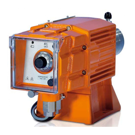
Operating instructions
Metering pump
ProMinent EXtronic
EXBb
®
EN
0158
Please carefully read these operating instructions before use. · Do not discard.
The operator shall be liable for any damage caused by installation or operating errors.
The latest version of the operating instructions are available on our homepage.
Part No. 987094
Original operating instructions (2006/42/EC)
BA EX 0 16 09/19 EN
Advertisement
Table of Contents

Related Manuals for ProMinent EXtronic EXBb


Summary of Contents for ProMinent EXtronic EXBb
-
Page 1: Operating Instructions
Operating instructions Metering pump ProMinent EXtronic EXBb ® 0158 Please carefully read these operating instructions before use. · Do not discard. The operator shall be liable for any damage caused by installation or operating errors. The latest version of the operating instructions are available on our homepage. - Page 2 Supplemental directives Supplementary information Read the following supplementary information in its entirety! You will benefit more from using the operating instructions should you already know this information. The following are highlighted separately in the document: Enumerated lists Fig. 1: Please read! Instructions ð...
-
Page 3: Table Of Contents
Table of contents Table of contents Identity code................5 Safety chapter............... 7 Storage, transport and unpacking........12 Overview of equipment............13 Functional description............15 5.1 Drive Unit..............15 5.2 Liquid End..............15 5.3 Self-Bleeding.............. 15 5.4 Diaphragm rupture sensor (optional)......15 5.5 Metering rate............... - Page 4 Table of contents Ordering information for fuses..........66 Declaration of Conformity........... 68 Index................... 69...
-
Page 5: Identity Code
Identity code Identity code Product range ProMinent EXtronic ® , Version b EXBb Degree of protection Gas explosion protection Firedamp and gas explosion protection Pump type refer to nameplate Dosing head material PP with bleed valve, O-ring: EPDM PP without bleed valve/ HV, O-ring: EPDM... - Page 6 Identity code Product range ProMinent EXtronic , Version b ® Manual with potential-free ON / OFF, [i,a] Control version with potentiometer with push-button for maximum frequency with push-button switch-over for maximum frequency Certification/voltage/language BVS Europe / 100–500 V / German BVS Europe / 100–500 V / English...
-
Page 7: Safety Chapter
The pump may only be used after it has been correctly installed and started up in accordance with the technical data and specifications contained in the operating instructions. Observe the general limitations with regard to viscosity limits, chemical resistance and density - see also ProMinent ® Resist‐ www.prominent.com ! ance List in the Product Catalogue or at All other uses or modifications are prohibited. - Page 8 Safety chapter The pump is not intended for exterior applications without the implementation of suitable protective measures. The pump should only be operated by trained and authorised personnel - see the following "Qualifications" table. You have a responsibility to adhere to the information con‐ tained in the operating instructions at the different phases of the unit's service life.
- Page 9 Service The Service department refers to service technicians, who have received proven training and have been authorised by ProMinent to work on the system. Safety information WARNING! Warning of personal injury and material damage –...
- Page 10 – The metering behaviour of the pump changes if a different liquid end size is fitted. Isolating protective equipment Only ProMinent Service may open the housing. Other safety equipment Adhesive labels WARNING! – The following safety information must be affixed to pumps that contain parts made of electrically non-conducting plastic.
- Page 11 Safety chapter D o n o t o p e n w h e n e n e r g i s e d ! A f t e r s w i t c h i n g o f f , w a i t t w o m i n u t e s b e f o r e o p e n i n g ! Fig.
-
Page 12: Storage, Transport And Unpacking
Storage, transport and unpacking Storage, transport and unpacking Safety information WARNING! Only return metering pumps for repair in a cleaned state and with a flushed liquid end - refer to "Decommissioning! Only return metering pumps with a completed Decontamination Declaration form. The Decon‐ tamination Declaration constitutes an integral part of an inspection / repair order. -
Page 13: Overview Of Equipment
Overview of equipment Overview of equipment... - Page 14 Overview of equipment - Drive unit with controller - Pressure connector - Backplate - Liquid end - Bleed valve (only for the 1000 - 0417 NP and PP types) - Bypass hose sleeve (only for the 1000 - 0417 NP and PP types) - Suction connector - Nameplate...
-
Page 15: Functional Description
Functional description Functional description 5.1 Drive Unit The diaphragm is driven by an electromagnet, which is controlled by an electronic controller. 5.2 Liquid End The dosing process is performed as follows: The diaphragm is pressed into the dosing head; the pressure in the dosing head closes the suction valve and the feed chemical flows through the discharge valve out of the dosing head. -
Page 16: Metering Rate
Functional description Fig. 4 Backplate Adapter Intermediate bushing Additional diaphragms Adapter plate Metering diaphragm Dosing head Fixing bolt Diaphragm rupture sensor 10 Feed channel CAUTION! Only above approximately 2 bar system back pres‐ sure is an electrical signal triggered in the event of diaphragm rupture. -
Page 17: Control Types
Functional description 5.6 Control types ”Internal stroke rate setting” (Identity code characteristic "Control type": 0) The controlling pulse is internally generated and adjusted using the stroke rate control knob (16). “External contact control” (Identity code characteristic "Control type": 1, 4): The controlling pulse is externally generated from potential-free or semiconductor contacts and fed to the drive unit via the "external control"... -
Page 18: Assembly
Assembly Assembly Compare the dimensions on the dimension – sheet with those of the pump. WARNING! Danger of electric shock If water or other electrically conducting liquids pen‐ etrate into the drive housing, in any other manner than via the pump's suction connection, an electric shock may occur. -
Page 19: Installation, Hydraulic
Installation, hydraulic Installation, hydraulic WARNING! EX pumps in areas at risk of explosion – Metering pumps in areas at risk of explosion are provided, as a matter of course, with an appropriate safety relief valve on the outlet side of the metering pump (which is used to protect against excessive heating due to overloading and impact sparks caused by the breakage of power end parts triggered by overloading.) - Page 20 Installation, hydraulic WARNING! The following measures are beneficial when working with highly aggressive or hazardous feed chemicals: – Install a bleed valve with recirculation in the storage tank. – Install a shut-off valve on the discharge or suc‐ tion side. CAUTION! Warning of feed chemical spraying around PTFE seals, which have already been used / com‐...
- Page 21 Installation, hydraulic CAUTION! Uncontrolled flow of feed chemical Feed chemical may press through the metering pump in an uncontrolled manner in the event of excessive priming pressure on the suction side of the metering pump. – Do not exceed the maximum permissible pri‐ ming pressure for the metering pump or –...
-
Page 22: Standard Installation
Installation, hydraulic 7.1 Standard installation P_EX_0021_SW Fig. 5: Standard installation Main line Storage tank Key for all hydraulic diagrams Symbol Explanation Symbol Explanation Metering pump Foot valve with filter mesh Injection valve Filter insert Adjustable back Interim tank with float pressure valve valve (also used as a relief... -
Page 23: Information On The Discharge-Side Installation
Installation, hydraulic Length of suction line Keep the suction line as short as possible. P_MAZ_0057_SW Fig. 7 Height difference, suction side The height h (see diagram) may only be smaller than or equal to the suction lift of the pump P divided by the density rho of the feed chemical: h (in m)≤... -
Page 24: How Not To Install
A relief valve with a return into the storage tank is useful as overload protection for the discharge line, for example install a ProMinent multifunctional valve. ® Use a pulsation damper to dampen pressure peaks with a metering stroke with long discharge lines or increase the pipe cross-section. -
Page 25: Special Installation Instructions
Installation, hydraulic Fault description Cause Remedy Ä ‘With high suction- feed chemical The suction-side priming pressure is too Install as shown in presses through the high due to the negative pressure differ‐ side pressure 3’ on page 26 or Ä ‘With liquid end. - Page 26 Installation, hydraulic With high suction-side pressure 3 Install an adjustable back pressure valve in the discharge line and install a shut-off valve in the suction line, which has to be closed when the pump is at a standstill (preferably a solenoid valve).
-
Page 27: Installation, Electrical
Installation, electrical Installation, electrical WARNING! EX pump in areas at risk of explosion – When installing the metering pump, observe the installation instructions for devices in areas at risk from explosion. – Note the enclosed documentation for the indi‐ vidual electrical components. WARNING! Danger of electric shock Unprofessional installation may lead to electric... - Page 28 Installation, electrical Mains connection WARNING! The safety fuse used internally has a switching capacity of 1500 A. If the short-circuit current in the supply network may be greater than 1500 A, the pump should be fused with an appropriate pre-fuse with a higher switching capacity (rated current of less than 1500 A).
- Page 29 Installation, electrical EXtronic Inductive consumer Varistor Provide own contacts, supply voltage via contactor relay or relay. With the 100 V to 230 V versions, connect Varistor (U = 275 V) or RC member (0.22 µF / 220 Ω) in parallel. The connection terminal (23) for the potential equalisation line is located on the housing next to the mains connection (12).
- Page 30 Installation, electrical Diaphragm rupture sensor (optional) CAUTION! Danger resulting from unnoticed diaphragm rup‐ ture If the pump has been ordered with an electric dia‐ phragm rupture sensor, it must also be electrically installed. – Electrically wire the enclosed diaphragm rup‐ ture sensor to a suitable monitoring device.
-
Page 31: Start Up
Start up Start up WARNING! Danger of electric shock A mains voltage may exist inside the pump housing. – If the pump housing has been damaged, you must disconnect it from the mains immediately. It may only be returned to service after an authorised repair. - Page 32 Start up Disconnect discharge line from liquid end. Switch on pump using mains switch and allow it to run at maximum stroke length and stroke rate until the liquid end is filled completely and free of bubbles. Switch off the pump. Connect discharge line to liquid end.
-
Page 33: Determining Pump Capacity
Start up CAUTION! After 24 operating hours, re-tighten the screws on the dosing head. Tightening torques Data Value Unit Tightening torques for M4 screws: 2.5 ... 3.0 Nm Tightening torques for M5 screws: 4.5 ... 5.0 Nm 9.1 Determining pump capacity The actual pump capacity depends on stroke length, stroke rate and back pressure in the metering line. -
Page 34: Setting The Pump Capacity
Start up Tab. 6: Input data Example Pump capacity at medium 11.9 l/h (refer to performance back pressure: data) Desired pump capacity: 6 l/h Back pressure: 8 bar Tab. 7: Calculation and results Correction factor according to diagram: Pump capacity to be set: 6 l/h / 0.9 = 6.66 l/h Stroke length according to 80 %... - Page 35 Start up Switching on Fold up transparent cover (17). Switch on pump with mains switch. Setting stroke length Before setting the stroke length, release the lock lever: Push up lock lever (15). Set the calculated stroke length with the stroke length control knob (14).
-
Page 36: Troubleshooting
Troubleshooting Troubleshooting Safety information WARNING! Warning of hazardous feed chemical Should a dangerous feed chemical be used: it may escape from the hydraulic components when working on the pump, material failure or incorrect handling of the pump. – Take appropriate protective measures before working on the pump (e.g. - Page 37 Troubleshooting Fault description Cause Remedy Personnel Fluid escapes from the The screws in the dosing Tighten screws in dosing Instructed per‐ backplate. head are too loose. head crosswise - refer to sonnel "Repair" for tightening tor‐ ques. The metering diaphragm is Replace the metering dia‐...
-
Page 38: Maintenance
Maintenance Maintenance WARNING! It is mandatory that you read the safety information and specifications in the "Storage, Transport and Unpacking" chapter prior to shipping the pump. WARNING! Warning of hazardous feed chemical Should a dangerous feed chemical be used: it may escape from the hydraulic components when working on the pump, material failure or incorrect handling of the pump. - Page 39 Maintenance Liquid ends with bleed valve: Interval Maintenance work Quarterly* In addition: Check that the bypass line is fixed firmly to the liquid end. Check that the bleed valve is tight. Check the discharge and bypass line for kinks. Check that the bleed valve is operating correctly. * Under normal loading (approx.
-
Page 40: Repair
Unauthorised repairs inside the pump can result in an electric shock or loss of explosion protection. For this reason repairs inside the pump should only be carried out by a ProMinent branch office or representative, in particular the following: –... - Page 41 Repair With the pump running, set the stroke length to “0” with the stroke length control knob (14). Switch off the pump. Loosen the screws (24). Pull dosing head (4) with screws (24) approx. 5 mm out of backplate (3) and pump housing until no more resistance can be felt through the screws (24) when attempting to turn the dosing head (4).
-
Page 42: Checking Diaphragm Rupture Sensor
Repair Insert metering diaphragm (25) in backplate (3) and screw on 2 threads. Turn metering diaphragm (25) until the 4 holes of diaphragm (25) and backplate (3) are precisely aligned. The leakage hole (26) of backplate (3) must face downwards. For the following steps, see the next chapter. -
Page 43: Replacing Separating Diaphragm Of The Diaphragm Rupture Sensor
Repair 12.3 Replacing separating diaphragm of the diaphragm rupture sensor Disconnect the diaphragm rupture sensor from the monitor. When changing the diaphragm, unscrew the diaphragm rup‐ ture sensor from the dosing head. Grasp the upper section (2) of the diaphragm rupture sensor. Do not manipulate the lacquer-protected nut. - Page 44 Repair CAUTION! – Observe the tightening torques. – Check the tightening torque again after 24 operating hours. – With the PP version, also check the tightening torques again every three months. Tightening torques Data Value Unit Tightening torques for M4 screws: 2.5 ...
-
Page 45: Decommissioning And Disposal
Decommissioning and disposal Decommissioning and disposal 13.1 Decommissioning WARNING! Danger from chemical residue There is normally chemical residue in the liquid end and on the housing after operation. This chemical residue could be hazardous to people. – It is mandatory that the safety information in the "Storage, transport and unpacking"... -
Page 46: Disposal
Decommissioning and disposal Danger of damage to the device Take into account the information in the "Storage, transport and unpacking" chapter if the system is decommissioned for a temporary period. Disconnect the pump from the mains/power supply. Drain the liquid end by turning the pump upside down and allowing the feed chemical to run out. -
Page 47: Technical Data
Technical data Technical data 14.1 Performance data Pump Maximum pump capacity at maximum back Maximum pump capacity rate at medium back type pressure pressure EXBb stroke stroke 1000 0.19 0.051 0.03 0.27 72.5 0.071 0.038 2501 1.14 362.5 0.301 0.16 0.369 0.19 1601... - Page 48 Technical data Pump type Stroke rate Connector size Suction lift* Priming lift** Permissible pri‐ outside dimen‐ ming pressure, sion x inside suction side diameter EXBb Strokes/min m water column m water column bar 1002 0308 2502 2505 1006 1310 0613 0814 12x9 0417...
-
Page 49: Precision
Technical data Tab. 9: Metering pumps with self-bleeding dosing head *** Pump Maximum pump capacity at maximum back Maximum pump capacity rate at medium back type pressure pressure EXBb Ml / Ml / stroke stroke 1601 0.66 0.174 0.09 1201 0.265 0.14 0803... -
Page 50: Material Specifications
Technical data 14.3 Material specifications NP1 /NP3 NS3 Dosing Polypro‐ Polypro‐ Clear Clear PTFE Stainless head pylene pylene acrylic acrylic with steel carbon 1.4404 Suction / Polypro‐ Polypro‐ PTFE Stainless pressure pylene pylene with steel connector carbon 1.4404 Seals EPDM EPDM FPM-A FPM-A/B... - Page 51 Technical data Control using potential-free contact or semiconductor switch: Residual current max. (contact 70 μA open): Contact resistance (closed) max.: 10 kΩ Maximum drop in voltage: Maximum pulse frequency: 40 pulses/s Pulse width min.: 10 ms Ä Chapter 14.5.1.2 ‘For "intrinsi‐ * To ensure intrinsic safety - see cally safe"...
-
Page 52: Electrical Data For Supply Current Circuit
Technical data * A cable length of 10 m is taken into account. For detailed data and when using in areas at risk of explosion, observe operating instructions and type examination certificate of diaphragm rupture sensor. 14.5.2 Electrical data for supply current circuit 14.5.2.1 For "non-intrinsically safe"... - Page 53 Technical data Tab. 16: Pump types 1002 , 2502, 1006, 0613, 0417 Mains connection (V) Max. current con‐ sumption*** (A) Effective power con‐ 0.70 0.70 0.33 0.41 0.14 sumption Mean power consump‐ tion (W) Fuse item 65* value 2.5T 2.0T 1.25T 0.8T 0.63...
-
Page 54: Ambient Conditions
Technical data 14.6 Ambient conditions Temperatures Permissible storage and transport tem‐ -20 ... +50 °C -4 °F ... +122 °F perature: Permissible ambient temperature during -20 ... +45 °C -4 °F ... +113 °F operation (power end/drive and control): Permissible temperature during operation -10 °C ... -
Page 55: Dimensional Drawing
Dimensional drawing Dimensional drawing Dimensions in mm ProMinent EXtronic EXBb ® NP=13 PP=11,5 40 50 60 Ø 5,8 Version ,,NS, PS“ Version ,,SB“ Type Material Ø D Ø F version 1000, 1601, 1201, 0803 1002, 0308, 2502, 2505, 1006 1310, 0613... - Page 56 Dimensional drawing Type Material Ø D Ø F version 0260 DN15 1000, 1601, 1201, 0803 1002, 0308, 1006 0613 0814, 0417 12x9 0430 DN10 0260 DN15 1002 DN10 1006 DN15 1310 DN15 0814 DN15 1000, 1601, 1201 0803 1002, 0308, 1006 0613 0814, 0417...
- Page 57 Dimensional drawing Type Material Ø D Ø F version 0430 Rp 1/4 0260 Rp 1/2 1601, 2501 Rp 1/4 1601, 1201, 0803 1002 1601, 1201, 0803 1002...
-
Page 58: Nomographs
Nomographs Nomographs EXBb_1000 0.625 0.30 5.04 0.25 4.00 0.563 0.20 3.00 0.500 0.15 0.438 2.00 0.12 0.09 1.50 0.375 0.07 1.00 0.313 0.05 0.70 0.04 0.250 0.03 0.50 0.40 0.02 0.30 0.188 0.015 0.20 0.012 0.15 0.01 0.10 0.005 0.07 0.004 Back pressure (bar) Pump capacity in relation to back pressure... - Page 59 Nomographs EXBb_1601 1.30 21.67 1.250 16.00 1.125 0.90 13.00 1.000 0.60 10.00 8.00 0.875 0.40 6.50 5.50 0.750 0.26 4.33 3.50 0.625 0.18 2.70 2.17 0.13 0.500 0.10 1.50 0.08 0.06 1.00 0.80 0.375 0.04 0.60 0.03 0.40 0.02 0.30 0.015 0.20 0.01...
- Page 60 Nomographs EXBb_0803 3.90 1.250 65.00 58.00 3.40 1.125 3.00 50.00 2.50 40.00 1.000 35.00 2.00 0.875 1.70 27.00 1.42 23.67 0.750 1.20 20.00 1.00 15.00 0.625 0.80 11.50 10.00 0.60 0.50 0.500 8.00 0.39 6.50 0.30 5.00 0.375 0.25 4.00 0.20 3.00 0.15...
- Page 61 Nomographs EXBb_0308 171.67 1.250 10.30 150.00 8.00 1.125 120.00 6.00 1.000 100.00 5.00 80.00 0.875 4.00 65.00 3.42 57.00 0.750 47.00 2.50 40.00 2.00 0.625 30.00 1.50 25.00 20.00 0.500 1.03 17.17 0.80 13.00 10.00 0.60 0.375 0.50 8.00 0.40 6.00 0.30 5.00...
- Page 62 Nomographs EXBb_2505 80.00 1.250 4.80 3.80 60.00 1.125 3.00 45.00 2.50 1.000 35.00 2.00 1.65 25.00 1.30 0.875 19.00 1.00 0.85 14.17 0.750 0.60 10.00 0.45 7.57 0.625 6.00 0.35 0.25 4.00 0.20 3.00 0.15 2.00 0.10 1.50 0.08 0.06 1.00 0.08 0.04...
- Page 63 Nomographs EXBb_1310 1.250 11.90 198.33 10.00 160.00 1.125 8.00 120.00 1.000 6.00 100.00 5.00 80.00 0.875 4.00 60.00 0.750 3.00 50.00 2.30 38.33 0.625 1.80 28.00 1.50 1.19 19.83 0.500 15.00 0.90 0.70 10.00 0.50 0.375 8.00 0.40 6.00 0.30 4.00 0.20 3.00...
- Page 64 Nomographs EXBb_0814 256.67 1.250 15.40 12.50 200.00 1.125 10.00 160.00 1.000 8.00 120.00 0.875 6.00 90.00 0.750 4.11 68.50 55.00 3.00 0.625 40.00 2.00 0.500 1.54 25.67 20.00 1.00 15.00 0.375 0.80 11.00 0.60 8.00 0.40 6.00 0.30 4.00 0.20 3.00 Back pressure (bar) Fig.
- Page 65 Nomographs EXBb_0430 1.250 29.50 491.67 1.125 380.00 20.00 300.00 1.000 15.00 0.875 200.00 10.00 0.750 135.00 6.60 110.00 0.625 5.00 70.00 4.00 0.500 2.95 49.17 2.40 35.00 1.80 25.00 0.375 1.40 20.00 1.00 15.00 0.80 11.00 0.60 8.50 0.40 6.00 0.30 5.00 Back pressure (bar)
-
Page 66: Ordering Information For Fuses
Ordering information for fuses Ordering information for fuses Fuses Even if the pump drive is not to be opened under any circumstances, we would recommend: keeping suitable fuses in stock so that the service team has them to hand immediately if needed. Tab. - Page 67 Ordering information for fuses P_EX_0016_SW Fig. 39...
-
Page 68: Declaration Of Conformity
Declaration of Conformity Declaration of Conformity ProMinent GmbH Im Schuhmachergewann 5 - 11 DE - 69123 Heidelberg, Germany, hereby declare that the product specified in the following, complies with the relevant basic health and safety requirements of the Direc‐ tive, on the basis of its functional concept and design and in the version distributed by us. -
Page 69: Index
Index Index How not to install ......24 Hydraulic installation ..... . 19 Adhesive labels . - Page 70 Index Pump capacity ..... 33, 34, 58 Push-button ......17 Qualification of personnel .
- Page 72 ProMinent GmbH Im Schuhmachergewann 5-11 D-69123 Heidelberg, Germany Telephone: +49 6221 842-0 Fax: +49 6221 842-419 Email: info@prominent.com Internet: www.prominent.com 987094, 4, en_GB © 2018...
Need help?
Do you have a question about the EXtronic EXBb and is the answer not in the manual?
Questions and answers