Table of Contents
Advertisement
Operating Instructions
®
ProMinent
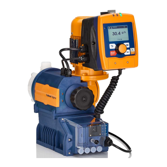
S1Ba (Basic Type)
S1Ca (Control Type)
Two sets of operating instructions are necessary to ensure the ProMinent
This product specific Sigma/ 1 operating instructions manual and the "General operating instructions
ProMinent
®
Please completely read through these operating instructions first! · Do not discard!
Part No. 987260
Sigma/ 1
S1Ca
are operated safely and reliably for their intended purpose:
motor-driven metering pumps and hydraulic accessories" are only valid if read together!
The warranty shall be invalidated by damage caused by operating errors!
ProMinent Dosiertechnik GmbH · 69123 Heidelberg · Germany
S1Ca
with left-hand liquid end
®
Sigma/ 1 S1Ba or S1Ca metering pumps
BA SI 012 07/02 GB
Advertisement
Table of Contents

Subscribe to Our Youtube Channel
Related Manuals for ProMinent Sigma/ 1 S1Ba


Summary of Contents for ProMinent Sigma/ 1 S1Ba
- Page 1 S1Ca (Control Type) S1Ca S1Ca with left-hand liquid end Two sets of operating instructions are necessary to ensure the ProMinent ® Sigma/ 1 S1Ba or S1Ca metering pumps are operated safely and reliably for their intended purpose: This product specific Sigma/ 1 operating instructions manual and the ”General operating instructions ProMinent ®...
- Page 2 Control elements and key functions Control elements: overview 1 Operating light (green) 2 Warning light (yellow) 3 Error warning light (red) 4 Stroke length adjuster 5 LCD display 6 UP key 7 DOWN key 8 P key 9 STOP/START key 10 i key 11 Relay output (optional) 12 Metering monitor socket...
- Page 3 Operating-/Settings Diagram Bedien-/Einstellschema Continuous Dauer- display anzeige Start/stop pump Pumpe stoppen/starten STOP STOP START START ➀ = Lock (CODE 1) = Sperrung (CODE 1) ➁ Change directly alterable values = Lock (CODE 2) Direkt veränderbare Größen ändern = Sperrung (CODE 2) Ansaugen Prime Charge starten (nur in Betriebsart "Batch")
- Page 4 p. 44 p. 46 p. 47 Calib p. 31 Calib p. 48 p. 48 p. 48...
- Page 6 Dulcodes UV-Desinfektionsanlage Imprint Imprint Operating Instructions for ProMinent ® Sigma/ 1 S1Ba/S1Ca © ProMinent Dosiertechnik GmbH, 2002 ProMinent Dosiertechnik GmbH Im Schuhmachergewann 5-11 69123 Heidelberg P.O. Box 101760 69007 Heidelberg · Germany info@prominent.de www.prominent.de Subject to technical modifications. ® ProMinent...
-
Page 7: Table Of Contents
Dulcodes UV-Desinfektionsanlage Table of contents Page Device Identification/Identity Code ® Notes on safety of ProMinent metering pumps General notes Notes on installation, start-up and operation Notes on maintenance and repair Product description S1Ba/S1Ca Identification of pump type Design/Functional description 2.2.1 Functional description, drive 2.2.2... - Page 8 Cancel total stroke number or total litres (CLEAR window) Operating Manual operation Remote control Troubleshooting Decommissioning and disposal Spare parts and accessories Annex Motor data sheet EC Declaration of Conformity Exploded diagrams of liquid ends Stroke actuator wiring diagram Stroke adjuster wiring diagram ® ProMinent Page 8...
-
Page 9: Device Identification/Identity Code
Union nut and PVDF insert Union nut and stainless steel insert Union nut and PVDF hose nozzle Union nut and stainless steel hose nozzle Version: ® With ProMinent logo (standard) Without ProMinent ® logo Electrical power supply: 3 ph, 230 V/400 V 50/60 Hz, 0.09 kW 1 ph, AC, 230 V/50/60 Hz, 0.09 kW... - Page 10 Union nut and PVDF insert Union nut and stainless steel insert Union nut and PVDF hose nozzle Union nut and stainless steel hose nozzle Version: ® With ProMinent logo Without ProMinent ® logo Electrical power supply: 3 ph, 230 V/400 V, ±10 %, 50/60 Hz...
-
Page 11: Notes On Safety Of Prominent Metering Pumps
® metering pumps must not be assembled with parts which are not tested and recommended by ProMinent otherwise this can lead to injury to persons and damage to property for which no liability will be accepted! • Pumps must be accessible at all times to facilitate operation and maintenance. -
Page 12: Notes On Maintenance And Repair
Notes on safety of ProMinent ® metering pumps Dulcodes UV-Desinfektionsanlage NOTICE • Set stroke length only with pump in operation! IMPORTANT • The pump must be secured in such a way that no vibrations can occur! The valves of the liquid end must always be positioned vertically in order to ensure trouble-free operation! •... -
Page 13: Product Description S1Ba/S1Ca
• Operate the pump only within the conditions described in the technical data! • General restrictions with regard to viscosity limits, chemical resistance and density must ® be observed (refer to ProMinent chemical resistance list (catalogue or homepage))! • All other applications or conversion are prohibited! •... -
Page 14: Stroke Movement
75 % 30 % Fig. 5 IMPORTANT A large stroke length and low metering frequency should be selected for very viscous media! A shorter stroke length and high frequency should be selected to achieve good mixing properties! ® ProMinent Page 14... -
Page 15: Metering Capacity Diagram
Dulcodes UV-Desinfektionsanlage Product description S1Ba/S1Ca 2.2.3 Metering capacity diagram ® ProMinent Page 15... - Page 16 • The metering output of S1Ba at 60 Hz is approximately 1.2 times the metering output of S1Ba at 50 Hz. • For pump types S1Ca, the output data at 60 Hz apply (for S1Ca, however, only 200 strokes/min. are possible). ® ProMinent Page 16...
-
Page 17: Functional Description, Delivery Unit
The connection dimensions of valves and liquid ends of the same size but with different materials are identical. These parts can be interchanged as required. Materials and dimensions are specified in Section 3, Technical data. Fig. 6 3154-4 ® ProMinent Page 17... -
Page 18: Integrated Overflow Valve With Bleeder Function
Overflow valve Sigma/ 1 liquid end, 7 bar PVT Identcode Type: 07042, 07065 *colour of cap – black Overflow valve Sigma/ 1 liquid end, 4 bar PVT Identcode Type: 04120 *colour of cap – red Fig. 7 3160-4 ® ProMinent Page 18... - Page 19 130 which is controlled by the lower spring force of bleeder spring item 133. NOTICE Once the pump has primed, turn knob item 139 in clockwise direction as far as it will go ”close“! The pump can now be placed into operation. ® ProMinent Page 19...
-
Page 20: Diaphragm Rupture Sensor
The leak tightness of the working diaphragm, Item 200, is monitored with a diaphragm failure detector, Item 104, that triggers a contact signal in the event of diaphragm failure so that the pump is stopped in the S1Ca and the diaphragm failure is indicated on a LCD. ® ProMinent Page 20... - Page 21 The diaphragm rupture sensor lens should be replaced after every diaphragm rupture. FM 050 Identcode Type: 10022, 10044, 10050, 12017, 12035 FM 065 Identcode Type: 07042, 07065 Fig. 9 FM 120 Identcode Type: 04084, 04120 3162-4 ® ProMinent Page 21...
- Page 22 Before commencing operation, install the provided diaphragm breakage sensor together with the gasket (Item159) and make the electrical connections. IMPORTANT • For safety reasons it is advisable to connect a safe low voltage (e.g. EN 60335-1 (SELV)). • The cable priority is arbitrary. ® ProMinent Page 22...
-
Page 23: Technical Data
10022 SST "-10 10044 PVT "-10 10044 SST "-10 07065 PVT "-10 07065 SST "-10 07042 PVT 1"-15 07042 SST 1"-15 12.5 04084 PVT 1"-15 04084 SST 1"/15 12.5 04120 PVT 1"-15 04120 SST 1"-15 12.5 ® ProMinent Page 23... - Page 24 Under constant conditions and in minimum stroke length of 30 % corresponding to following notes, the reproducibility of the metered quantity is better than ±2 %. All specifications refer to metered quantities with water at 20 °C and correct installation of the metering pump. ® ProMinent Page 24...
-
Page 25: Dimensions Sigma/ 1
04120 SST Sigma 07042, 04084, DN 15 242 164 G 1 A 114 285 305 04120 SST - ÜV-A Dimensions with ** diaphragm rupture sensor, # cover, basic model ## Controller cover, ### Controller cover (pacing relay) ® ProMinent Page 25... -
Page 26: Dimensions Sigma/ 1 With Servo Motor
04120 SST Sigma 07042, 04084, DN 15 242 164 G 1 A 279 299 04120 SST - ÜV-A Dimensions with ** diaphragm rupture sensor, # cover, basic model ## Controller cover, ### Controller cover (pacing relay) ® ProMinent Page 26... -
Page 27: Dimensions Sigma/ 1 With Left Hand Liquid End
1 ph IP 55 230 V 50/60 Hz 0.09 kW ..V Three phase motor with integrated speed changer For more details you can request the motor specification sheets. Custom motors and/or custom motor flanges are available on request. ® ProMinent Page 27... -
Page 28: Stroke Adjuster
Motor: IP 55 DIN EN 60034-5 (in accordance with DIN VDE 0470 Part 1, corresponds to EN 60529 and IEC 529). External fan External fan for speed controlled motor with external fan and temperature monitor: Note information in “General operating instructions for ProMinent ® metering pumps and Fig. 13 hydraulic accessories”. -
Page 29: Start-Up/Maintenance
NOTICE Observe the safety notes provided in Section 1. Start-up ® All general guidelines in the accompanying ”General operating instructions ProMinent motordriven metering pumps and hydraulic accessories” apply. Maintenance NOTICE After loosening the liquid end screws (e.g. to change the valves or diaphragm), the screws must be retightend corsswise to the specified tightening torque. - Page 30 If suction problems with the pump or leakage at the overcurrent valve are encountered, first clean the ball and the ball seat disc. • For media containing particles larger than 0.3 mm it is absolutely essential to install a filter in the suction line. ® ProMinent Page 30...
-
Page 31: Features Of The S1Ca Metering Pumps
130 W 130 W Nominal current 1.2 A Peak current (in operation) Making peak current 16 A Fuse, internal* 3.15 AT (1.5kA) 3.15 AT (1.5kA) * Only genuine fuses of ProMinent, item no. 732414, may be used! ® ProMinent Page 31... -
Page 32: Function Description, Controller
” mode: (Identity code, control variant: PROFIBUS ® ® This operating mode provides the option of controlling the pump via the PROFIBUS (see ® ® “Supplementary instructions for ProMinent gamma/ L and ProMinent Sigma versions with PROFIBUS ® ”). Functions The following functions can be selected using the SET menu: “Calibrate”... - Page 33 (as long as it is operable) 2. “Fault”, “stop” and “pause” stop all system parts up to “prime”. 3. The stroke rate of the “auxiliary frequency” always overrides the stroke rates of the operating modes listed in point 4. ® ProMinent Page 33...
-
Page 34: Sockets, Symbols And Wiring Diagram
(2) External socket for contact or analogue controller with zero volts deactivation via pause function (with function plug* - not illustrated) (3) Metering monitor socket for connection of ProMinent ® metering monitor (4) Mains switch (1-pin) - Page 35 Auxiliary frequency: grey and black closed -> pump metering at pre-set stroking rate Diaphragm rupture cable External/contact cable (2 core) Contact open -> alarm -> pump stops with controller type 0 Contact closed -> metering stroke ® ProMinent Page 35...
- Page 36 Controller: – zero volts contact (approx. 0.5 mA) – semi-conductor (residual voltage: < 0.7 V) * The metering pump makes its first metering stroke at approx. 0.4 mA (4.4 mA) and starts continuous operation at approx. 19.2 mA. ® ProMinent Page 36...
- Page 37 Fault green/C (fault) indicating Diaphragm Diaphragm 2 blue/alarm white/NO (pacing) rupture rupture 1 black/GND pacing relay sensor sensor brown/C (pacing) 3 blue/analogue 2 white/contact Circuit External 1 brown/pause examples activation 4 black/GND overleaf 5 grey/auxiliary Mains ® ProMinent Page 37...
- Page 38 Features of the S1Ca metering pumps Features of the S2Ca metering pumps Dulcodes UV-Desinfektionsanlage Circuit examples: universal signal cable by customer Cable Pump, inside „External contact“ function ® (ProMinent external/contact cable) 2 white/contact two-core External activation 4 brown/GND Pulse rate, e.g. contact water meter „External contact“...
-
Page 39: Retrofitting Relays
The pump is generally programmed ex-factory to „drop-out action alarm relay“ and – if fitted – „pull-up action clock pulse generator relay“. If a switching function is required, the pump can be reprogrammed at the Heidelberg plant (not necessary by PROFIBUS ® -version). Fig. 17 Fig. 18 ® ProMinent Page 39... -
Page 40: Control Elements
The number of strokes reached is above the maximum value (99999) that can be shown in the LCD display. IMPORTANT When calibrated, the S1Ca displays the feed rate and the feed capacity in l and/or in l/h or in gal and/or g/h. ® ProMinent Page 40... -
Page 41: Settings
For “change a figure”; press the P key 1x; you will simultaneously move to the next menu option or to a continuous display. Correct wrongly set digits Press the i key 2x; you will go back to the first digit. ® ProMinent Page 41... -
Page 42: Check Adjustable Values
In order to adapt the S1Ca to your process requirements you must: 1. Select the operating mode in the MODE menu. 2. Adjust settings to this operating mode in the SET menu. MODE menu CODE menu Continuous display menu CLEAR window ® ProMinent Page 42... -
Page 43: Select Operating Mode (Mode Menu)
0 mA the S1Ca does not operate at 20 mA the S1Ca operates at 180 strokes/min. Between these two extremes the stroke rate is proportional to the electrical signal. t e s g l a Analog Continuous display ® ProMinent Page 43... - Page 44 I1: the straight line and the ratio are fixed accordingly: I [mA] Fig. 21 IMPORTANT Draw a diagram like the one above - with values for (I1, F1) and (I2, F2) - in order to set the S1Ca to your required stroke rate! ® ProMinent Page 44...
-
Page 45: Settings For "Contact" Operating Mode (Contct Menu)
(fraction) or small increase in strokes. NOTICE The factor resets to “1” if you change to a different operating mode. The following versions are available: • Contact - identity code: external 1:1 • Contact - identity code: external with pulse control ® ProMinent Page 45... - Page 46 When the STOP/START key is pressed or the “pause” function is activated, the stroke memory is deleted (this can be avoided using the “memory” extension function, see below). You can optimally adapt the S1Ca to the respective process, e.g. in connection with contact water meters. ® ProMinent Page 46...
-
Page 47: Settings For "Batch" Operating Mode (Batch Menu)
Flow (FLOW menu, available only if flow monitor is connected) 7.5.1 Settings for “calibration” function (CALIB menu) t e s b i l t r a Calib Calib 2 3 2 0 0 2 Calib Calib Continuous display ® ProMinent Page 47... -
Page 48: Setting For "Auxiliary Frequency" Function (Aux Menue)
AUX menu. It can be activated via the “external control” terminal. When the auxiliary frequency is activated, “aux” appears in the LCD display. This auxiliary frequency overrides the current stroke frequency set for the selected operating mode. ® ProMinent Page 48... -
Page 49: Settings For The "Flow" Function (Flow Menu)
(= set to “0”). You may then press the P key briefly to exit this window. The values displayed are counted incrementally from the point of commissioning the pump, or from the last delete action. r a e Continuous display ® ProMinent Page 49... -
Page 50: Operating
The S1Ca returns to the original continuous display a few seconds after the factor has been reset. Display program version Press the P key for 10 seconds to display the program version. Example: “V1052” + “X1010”. In the case of “LOAD3” release the key immediately! ® ProMinent Page 50... -
Page 51: Remote Control
Remote control of the S1Ca is possible via a control cable or PROFIBUS ® (see Section 5.3 and ® ® Chapter 7, „Supplementary instructions for ProMinent gamma/ L and ProMinent Sigma ® versions with PROFIBUS “ as well as your documentation in the appendix). - Page 52 Press the P key (reset key). Cause Other motor fault. Remedy Call ProMinent. Press the P key (reset key). Red LED is lit. “Error” appears in the display and “TEMPERATURE” is flashing Cause The temperature in the pump housing is too high because the ambient temperature is too high.
-
Page 53: Decommissioning And Disposal
Cause Controller fault. Remedy Disconnect the pump from the mains and reconnect. If the error message continues, send the pump back to ProMinent. Red LED lights up, “Error” appears in the display and “Menu” flashes. Cause Stroke buffer full Remedy Rectify fault Press P key (Make a note of what effect this has on your process). -
Page 54: Spare Parts And Accessories
® The assembly and installation of ProMinent metering pumps with other-make parts that are not tested and recommended by ProMinent are not permitted and can lead to personal injury and damage to property for which no liability shall be accepted! -
Page 55: Annex
400-480/250-280 V (60Hz) Nr. 1018433 20:1 These gear motors are available with the above transmissions. Nr./no. ProMinent MD-1018455 Pumpentyp: S1Ba – – – – – – – S – – – Datum/Date S1Ca – – – – – – – U – – –... -
Page 56: Ec Declaration Of Conformity
EC Declaration of Conformity Dulcodes UV-Desinfektionsanlage ® ProMinent Page 56... -
Page 57: Exploded Diagrams Of Liquid Ends
Ball seat * Valve assy DN 15/PVT* Order No. 792517 Spare parts kit FM 120 PVT Order No. 1010543 * The listed items are constituent parts of the spare part kit. Fig. 25 Subject to technical modifications. 61_05-104_00_99-03_2 ® ProMinent Page 57... - Page 58 Overflow valve assy 7 bar PVA Order No. 740811 Overflow valve assy 4 bar PVA Order No. 740812 For other spare parts see delivery unit without overflow valve (see p. 56 and p. 57). Fig. 26 Subject to technical modifications. 61_05-104_01_00-03_2 ® ProMinent Page 58...
- Page 59 Spare parts kit FM 65 SST without valve Order No. 1010557 * The listed items are constituent parts of the spare part kit. ** Special accessories (not included in spare part kit). Fig. 27 Subject to technical modifications. 61_05-104_01_01-03_2_norm ® ProMinent Page 59...
- Page 60 Spare parts kit FM 120 SST without valve Order No. 1010558 Spare parts kit FM 120 SST with valve Order No. 1010559 * The listed items are constituent parts of the spare part kit. Fig. 28 Subject to technical modifications. 61_05-104_01_01-03_2_norm ® ProMinent Page 60...
- Page 61 Overflow valve assy 7 bar SSA Order No. 740815 Overflow valve assy 4 bar SSA Order No. 740814 For other spare parts see delivery unit without overflow valve (see p. 59 and p. 60). Fig. 29 Subject to technical modifications. 61_05-104_01_01-03_02 ® ProMinent Page 61...
- Page 62 S1Ca Retrofit kit double diaphragm FM 120 Order No. 1009851 Lense Order No. 792807 Diaphragm failure detector * * The listed items are constituent parts of the spare part kit. Fig. 30 Subject to technical modifications. 61_05-104_00_98-03_2 ® ProMinent Page 62...
-
Page 63: Stroke Actuator Wiring Diagram
Dulcodes UV-Desinfektionsanlage Wiring diagram Stroke actuator wiring diagram Input, Output: Actual valve ground Actual valve I o.U Setpoint I o.U Setpoint ground 4 3 2 1 Stroke adjuster wiring diagram Sig. ® ProMinent Page 63...
Need help?
Do you have a question about the Sigma/ 1 S1Ba and is the answer not in the manual?
Questions and answers