Table of Contents
Advertisement
Quick Links
Operating instructions
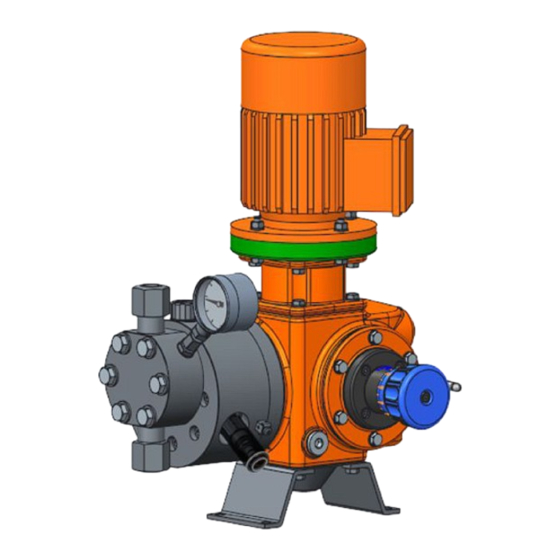
Metering pump
Evolution E1Sa
These operating instructions form part of combined documentation and, as such, are only valid if used in conjunction with
the combined documentation.
Target group: trained, qualified personnel, unless otherwise required.
Please carefully read these operating instructions before use. · Do not discard.
The operator shall be liable for any damage caused by installation or operating errors.
The latest version of the operating instructions are available on our homepage.
999638
A3500
Original operating instructions (2006/42/EC)
EN
Version: BA ORL 014 07/23 EN
Advertisement
Table of Contents

Related Manuals for ProMinent Evolution E1Sa


Summary of Contents for ProMinent Evolution E1Sa
- Page 1 Operating instructions Metering pump Evolution E1Sa A3500 These operating instructions form part of combined documentation and, as such, are only valid if used in conjunction with the combined documentation. Target group: trained, qualified personnel, unless otherwise required. Please carefully read these operating instructions before use. · Do not discard.
- Page 2 Supplemental directives General non-discriminatory approach In order to make it easier to read, this document uses the male form in grammatical structures but with an implied neutral sense. The document is always aimed equally at women, men and gender-neutral persons. We kindly ask readers for their understanding in this simplification of the text.
-
Page 3: Table Of Contents
Table of contents Table of contents Function................... 5 1.1 Functional description............. 5 1.2 Field of application..............5 1.3 Accessories................5 1.4 Overview of equipment............6 1.5 Liquid end................7 1.6 Diaphragm monitor..............8 1.7 Nameplate................9 1.7.1 Nameplate data..............9 1.7.2 ATEX nameplate data............ - Page 4 Table of contents 9.3 Replacing the diaphragm............39 9.3.1 A diaphragm rupture can remain unnoticed....... 39 9.3.2 Drain the hydraulic oil from the hydraulic end....39 9.3.3 Replacing the diaphragm........... 40 9.3.4 Tightening torque for screws..........41 9.3.5 Filling hydraulic oil into the hydraulic end......41 Maintenance..................
-
Page 5: Function
Function Function 1.1 Functional description The pump is an oscillating-action process metering pump with a PTFE two-layer safety diaphragm. An electric motor drives the pump. The drive unit generates the oscillating force-stroke needed for the displacement process from the rotational movement of the motor. The displacement body driven by the drive unit converts the force-stroke movement into hydraulic energy. -
Page 6: Overview Of Equipment
Function 1.4 Overview of equipment This pump consists of the following main assemblies: A3526 Fig. 1: Overview of the main assemblies Evolution 1 S (abbreviated to Evo1 S) Multiple pump, connection kit Motor 10 Base Motor base 11 Lubrication oil Stroke adjustment 12 Liquid end Stroke adjustment, manual... -
Page 7: Liquid End
Function 1.5 Liquid end A3841 Fig. 2: Liquid end of the PTFE multi-layer diaphragm (1) The heart of the liquid end is a PTFE multi-layer diaphragm (1). The PTFE multi-layer diaphragm hermetically seals the delivery chamber of the dosing head and causes displacement in the dosing head at each pump stroke. -
Page 8: Diaphragm Monitor
Function 1.6 Diaphragm monitor A3839 Fig. 3: The diaphragm monitoring interface (1), shown here with the visual display screwed in The diaphragm monitor monitors the multi-layer diaphragm for leaks and faults. The central slot of the multi-layer diaphragm features a drainage net. -
Page 9: Nameplate
XXX bar Temp. -20 ... +40 °C Hubzahl XXX bar XXX 1/min ProMinent GmbH, Im Schuhmachergewann 5 - 11 69123 Heidelberg, Germany A3529 Fig. 5: Nameplate data (example), explanation Type Identity code - see above p rtd Maximum pressure, as ordered... -
Page 10: Dimensional Drawing
Function 1.8 Dimensional drawing 1.8.1 Dimensional drawing, example Dimensional drawing, example Please use the dimensional drawing enclosed with the documentation for the dimensions for your specific pump. All dimensions are in mm. 40523784 A3505 Fig. 7: Dimensional drawing... -
Page 11: Dimensional Drawing With Stroke Control Motor
Function 1.8.2 Dimensional drawing with stroke control motor 40523784 A3840 Fig. 8: Dimensional drawing with stroke control motor... -
Page 12: Dimensional Drawing With Actuator/Horizontal
Function 1.8.3 Dimensional drawing with actuator/horizontal 40523784 A3847 Fig. 9: Dimensional drawing with actuator/horizontal... -
Page 13: Dimensional Drawing With Actuator/Vertical
Function 1.8.4 Dimensional drawing with actuator/vertical 40583784 A3848 Fig. 10: Dimensional drawing with actuator/vertical... -
Page 14: Identity Code
Identity code Identity code Tab. 2: ES1a Drive type Simplex (vertical) Drive (without liquid end) Piston Piston Ø6 Piston Ø8 Piston Ø10 Piston Ø13 Piston Ø22 Piston Ø30 Stroke rate 50 Hz operation 60 Hz operation 93 strokes/min. @ 50 Hz 113 strokes/min. - Page 15 Identity code ANSI flange NPT connector Drive (without liquid end) Electrical connection 3-phase, 230/400 V, 50/60 Hz 3-phase, 230/400 V, 50/60 Hz, with PTC 3-phase, 230/400 V, 50 Hz, (EXDE) T4 3-phase, 265/460 V, 60 Hz, (EXDE) T4 Controllable motor with integrated frequency converter PM China - 3-phase, 380 V, 50 Hz PM China - 3-phase, variable motor, 220 ...
-
Page 16: Explanation Of The Atex Label
Identity code Approval 0 CE 1 CE + ATEX 2 CE + EAC 3 CE + EAC+ ATEX 4 CE + UCKA 5 CE + UCKA + ATEX X Drive (without liquid end) Documentation * German English Drive (without liquid end) modified Unit of measure bar, l/h... -
Page 17: Safety Chapter
Safety chapter Safety chapter 3.1 Labelling of Warning Information Introduction These operating instructions provide information on the technical data and functions of the product. These operating instructions provide detailed warning information and are provided as clear step-by-step instructions. The warning information and notes are categorised according to the fol‐ lowing scheme. -
Page 18: User Qualification
Safety chapter 3.2 User qualification WARNING! Danger of injury with inadequately qualified personnel The operator of the system / equipment is responsible for ensuring that the qualifications are fulfilled. If inadequately qualified personnel work on the unit or loiter in the hazard zone of the unit, this could result in dangers that could cause serious injuries and material damage. -
Page 19: Warning Symbols Denoting Different Types Of Danger
Observe the general limitations with regard to viscosity limits, chem‐ ical resistance and density - see also the ProMinent Resistance List (in the Product Catalogue or at www.prominent.com)! Only suitable pumps can be used in areas at risk of explosion. - Page 20 – Take into account the resistance of the wetted mate‐ rials and the ProMinent Resistance List when selecting the feed chemical - see the ProMinent Product Catalogue or visit ProMinent. INFORMATION: Refer to the documentation for the bought-in parts. Installation height The standard version is intended for installation up to a height of 1,000 m above sea level.
-
Page 21: Emissions
Safety chapter WARNING! The inside of the dosing head needs to be constantly filled with medium in normal mode, and the start-up and run-down processes have to be designed in such a way by the operator so that no explosive mixture is produced inside the dosing head. -
Page 22: Storage And Transport
The "Decontamination Declaration Form" can be found at www.prominent.com. CAUTION! Use lifting points with suitable lifting means. Secure the pump to prevent it from falling. -
Page 23: Transport
Storage and transport Specification Value Maximum air humidity*: 95 % relative humidity *non-condensing (according to DIN IEC 60068-2-30) 4.2 Transport Fit the sealing stoppers in place of the vent screws for transport. The sealing stoppers provide secure protection against oil leakage. Ideally, use caps or similar to protect the connectors of the pressure and suction valve. - Page 24 Storage and transport A3842 Fig. 12: Template...
-
Page 25: Assembly
-20 °C ... +40 °C. Compare the dimensions on the dimensional drawing with those of the pump. If necessary: Refer to the dimensional drawings on our website www.prominent.com for assistance. Assembly of the motor - with designs without motor WARNING! The following instructions relevant in areas at risk from explosion apply in areas at risk from explosion. -
Page 26: Motor Number
Assembly 5.1 Motor number The motor number identifies the motor, A3849 Fig. 13: Motor flange 160 A3850 Fig. 14: Motor flange 200 Tab. 4: Hydro Model size Motor flange Identity code [MOT_E1Sa] 1, 4 (4=ATEX) 2, 5 (5=ATEX) NEMA 56/143 3, 6 (6=ATEX) Dimensions in mm - unless otherwise indicated. -
Page 27: Alignment Of The Liquid End
Assembly Risk of burns with hot feed chemical People are at risk of burning themselves if hot feed chemical can heat the liquid ends above the permissible surface temperatures. Consider attaching a “Hot surface” label to the liquid end or fit a guard. Position the pump so that control elements, such as the stroke length adjustment knob, the indicating dial A or the oil inspection window, are easily accessible. -
Page 28: Installation
Installation Installation 6.1 Pipework forces and torque The maximum loads at the pressure and suction connector are as follows: A3532 Fig. 18: Pipework force and torque coordinate system Tab. 5: Pipework forces and torque Screw connectors Flange connections Nominal width DN10 DN10 Fx [N]... -
Page 29: Installation, Hydraulic
Installation 6.2 Installation, hydraulic User qualification: trained qualified personnel Ä Chapter 3.2 ‘User qualification’ on page 18 WARNING! Danger from hazardous substances! Possible consequence: Fatal or very serious injuries. Please ensure when handling hazardous substances that you have read the latest safety data sheets provided by the manufacture of the hazardous substance. -
Page 30: Suction Lift
Installation The maximum permissible priming pressure on the suction side is 50% of the maximum permissible operating pressure. Too high a pri‐ ming pressure can significantly shorten the service life of the dia‐ phragm and also the mechanical components. Note that the pressure on the pressure side needs to be at least 1.5 bar higher than the priming pressure on the suction side. -
Page 31: Basic Installation Notes
Installation 6.2.3 Basic installation notes Examples P_MOZ_0043_SW Fig. 20: (A) standard installation, (B) with pulsation damper Main line Storage tank Tab. 6: Legend for hydraulic diagram Symbol Explanation Symbol Explanation Metering pump Foot valve with filter mesh Injection valve Level switch Back pressure valve or safety valve Manometer... -
Page 32: Installation, Electrical
Installation 6.3 Installation, electrical User qualification: electrical technician Ä Chapter 3.2 ‘User qualification’ on page 18 What requires electrical installation?: Motor External fan (identity code option) Frequency converter (identity code option) Stroke control drive (identity code option) Stroke actuator (identity code option) Diaphragm monitoring sensor (standard) Earthing wires (to be provided on site) Potential equalisation line (to be provided on site, prescribed in the... - Page 33 Installation CAUTION! Only motors with a frequency converter: The motor can be damaged The input current limiter could be damaged if a motor with integrated frequency converter is restarted within 3 minutes of the supply voltage being switched off. – After switching off, allow the unit to stand for at least 3 minutes before restarting.
-
Page 34: Earthing / Potential Equalisation
Installation The following applies in areas at risk from explosion: Note the details of the type examination certificate PTB 00 ATEX 2048 X for the NAMUR sensor NJ1.5-8GM-N as well. Other units Install the other units in line with their documentation. 6.4 Earthing / potential equalisation Note / comply with the following points: Electrical components must be properly earthed in accordance with... -
Page 35: Start Up
Start up Start up User qualification: trained qualified personnel Ä Chapter 3.2 ‘User qualification’ on page 18 WARNING! Danger from hazardous substances! Possible consequence: Fatal or very serious injuries. Please ensure when handling hazardous substances that you have read the latest safety data sheets provided by the manufacture of the hazardous substance. -
Page 36: Venting The Hydraulics
Start up Is the safety equipment correctly assembled and working properly? Is the electrical installation of the process pump correct and in accord‐ ance with local regulations? Is the supply voltage of the main power end, actuator, sensors etc. correct? Is the electrical installation (including potential equalisation and earthing) correctly installed and in accordance with local regulations? Is the system protected against overpressure, e.g. -
Page 37: Venting The Hydraulics With A Fixed Stroke Drive
7.3 Calibrate the stroke control drive (optional) The stroke control drive is calibrated to the capacity ordered ex-factory. Please contact ProMinent if you wish the stroke control drive to be cali‐ brated to another capacity. -
Page 38: Operation
Operation Operation User qualification: trained qualified personnel Ä Chapter 3.2 ‘User qualification’ on page 18 After prolonged operation, for instance at high ambient temperatures, hot feed chemicals, or severe pump load, areas of the pump may become hot enough to present a risk of combustion. The pump's stroke length can be changed when stationary and also when in operation. -
Page 39: Diaphragm Package
Diaphragm package Diaphragm package 9.1 Material versions There is a choice of 2 materials for the woven fabric between the dia‐ phragm layers: PET (polyethylene terephthalate) which can be used at temperatures of up to max. 120 °C PEEK (polyether ether ketone) which can be used at temperatures of up to max. -
Page 40: Replacing The Diaphragm
Diaphragm package 9.3.3 Replacing the diaphragm A3839 Fig. 23: The diaphragm monitoring interface (1), shown here with the visual display screwed in A3851 Fig. 24: Diaphragm Depressurise the suction and pressure lines. Is the hydraulic oil drained? Unscrew the suction and pressure lines from the liquid end. -
Page 41: Tightening Torque For Screws
Diaphragm package Unscrew the diaphragm (3) including anchor (4) and clamp disc (5) from the support disc (2). Screw the new diaphragm / diaphragm anchor combination onto the tie-rod (3), paying attention to the O-ring in the clamp discs (5). Make sure that the O-ring is not damaged. - Page 42 Diaphragm package Check the tightening torque of the dosing head screws again after 24 operating hours.
-
Page 43: Maintenance
Maintenance Maintenance User qualification: trained and qualified personnel, unless otherwise stated Ä Chapter 3.2 ‘User qualification’ on page 18 WARNING! Danger from hazardous substances! Possible consequence: Fatal or very serious injuries. Please ensure when handling hazardous substances that you have read the latest safety data sheets provided by the manufacture of the hazardous substance. -
Page 44: Inspection
Maintenance 10.1 Inspection We recommend inspecting the pump to ensure the fault-free operation of the pump. Check the pump installation for: Leaks, Abnormal noises or squeaking, Unusual temperatures, Unusual odours, Unusual vibrations, Other anomalies, Correct oil level. Daily, pump in operation: Diaphragm rupture warning system: No diaphragm rupture is dis‐... -
Page 45: Annually
Maintenance Overpressure: Immediately check the pressure relief valve and the seals of the liquid end and replace if necessary. Blocked suction line: Replace the PTFE diaphragm layers including woven fabric within 4 weeks. 10.2.2 Annually Oil: oil change including removal of deposits and accumulated water. General cleaning;... -
Page 46: Filling With Hydraulic Oil
Maintenance Check the hydraulic oil for excessive wear. Excessive wear can indicate damage to the worm gear. If the pump was also previously making unusual noises, have the worm gear precisely checked before starting it up again, and have it replaced if necessary. Place an oil trough under the hydraulic end. -
Page 47: Cleaning Valves
Maintenance 10.5 Cleaning valves 10.5.1 Cleaning a discharge valve (double ball) Disassembling the discharge valve Clean the discharge and suction valves only one after another, as the valves cannot be differentiated by the arrow markings. For orientation: Should you have a dismantled liquid end in front of you - the suction valve is on the side of the diaphragm monitoring sensor. -
Page 48: Cleaning A Suction Valve (Double Ball)
Maintenance Position the insert disc (6) with the flare on the assembly. The distance between the edge of the valve body and the insert disc (6) depends on the design. Place the large seal (7) between the insert disc (6) and the dosing head. -
Page 49: Repairing The Diaphragm Monitoring Sensor
Maintenance 10.8 Repairing the diaphragm monitoring sensor Visual display B1316 Fig. 30: Visual display Regularly clean the display. - Page 50 Maintenance 30 V-version Checking the diaphragm monitoring When changing the diaphragm, unscrew the diaphragm monitoring sensor sensor from the dosing head. Check for electrical continuity: Using a blunt insulating probe (Ø 2 ... 3 mm, no sharp edges), press into the channel of the diaphragm monitoring sensor. ð...
- Page 51 Maintenance ATEX version Checking the diaphragm monitoring When changing the diaphragm, unscrew the diaphragm monitoring sensor sensor from the dosing head. Check that the monitor does not indicate Using a blunt insulating probe (Ø 2 ... 3 mm, no sharp edges), press any diaphragm damage: into the channel of the diaphragm monitoring sensor.
-
Page 52: Rectifying Functional Faults
Rectifying functional faults Rectifying functional faults 11.1 Mechanical faults User qualification: trained and qualified personnel / elec‐ trical technician Ä Chapter 3.2 ‘User qualification’ on page 18 Fault Cause Remedy Remark Loud noises in the area of Bearing damage on the Replace bearing or motor Risk of ignition by sparking the drive motor... -
Page 53: Hydraulic Faults
Rectifying functional faults 11.2 Hydraulic faults Fault Cause Remedy Remark Pump does not meter Shut-off valve on the pressure or Check and, if necessary, Diaphragm position con‐ suction side is closed open the shut-off valves trol or pressure relief valve triggers Suction pressure too low Increase the suction pres‐... -
Page 54: Electrical Faults
Rectifying functional faults Discharge or suction valve dam‐ Check the condition of the aged discharge and suction valves and replace if necessary Delivery flow con‐ Gas formation in the delivery Use of special discharge and stantly drops chamber suction valves Various process parameters Check and, if necessary, cor‐... -
Page 55: Temporary Decommissioning
Temporary decommissioning Temporary decommissioning WARNING! Danger from hazardous substances! Possible consequence: Fatal or very serious injuries. Please ensure when handling hazardous substances that you have read the latest safety data sheets provided by the manufacture of the hazardous substance. The actions required are described in the safety data sheet. - Page 56 Temporary decommissioning Spread assembly paste on the threads of the vent valve before screwing in, as otherwise there is a risk of corrosion. Check the operation of the worm shaft seals, the push rod seals and the threaded shaft seal, and replace the seals if necessary.
-
Page 57: Decommissioning And Disposal
Decommissioning and disposal Decommissioning and disposal User qualification: trained and qualified personnel / elec‐ trical technician Ä Chapter 3.2 ‘User qualification’ on page 18 WARNING! Danger from hazardous substances! Possible consequence: Fatal or very serious injuries. Please ensure when handling hazardous substances that you have read the latest safety data sheets provided by the manufacture of the hazardous substance. -
Page 58: Technical Data
Technical data Technical data Always note the technical data on the nameplate, the pump data sheet supplied, and the other applicable documents provided. Their information has priority over the information given in this chapter. 14.1 Particle size Tab. 7: The following filters or filter inserts are recommended depending on the nominal valve diameter from a particle size of: Valve nominal diameter Maximum mesh width of the filter insert [mm]... -
Page 59: Weight
Technical data 14.4 Weight Tab. 9: Weight 0.37 kW motor approx. 6 kg 0.55 kW motor approx. 7.3 kg 0.75 kW motor approx. 7.3 kg Drive unit complete without oil approx. 16.7 kg Simple pump type 0 approx. 31 kg Simple pump type 2 approx. -
Page 60: Contact
Technical data 14.7.1 Contact Seal Top part Separating diaphragm Plate Body The contact is an N/C. The contact is potential-free. Protective low voltage: For safety reasons, we recommend connecting to protective low voltage, e.g. in accordance with EN 60335-1 (SELV ). The poles of the cable can be connected as required. -
Page 61: Namur Sensor, Specified For Areas At Risk From Explosion
Technical data 14.7.2 NAMUR sensor, specified for areas at risk from explosion Seal Top part Separating diaphragm 3 a Spring seat Plate Body Spring 5 ... 25 V DC, in accordance with NAMUR and/or DIN 60947-5-6, poten‐ tial-free design. Install the sensor in accordance with the “Installation, electrical” section. Refer to its documentation. -
Page 62: Sound Pressure Level
The relevant information can also be provided or requested by stating the serial number. 14.12 Filling volumes Mobilube 1 SHC 70W - 90, ProMinent part no. 1005823 Filling volume: approx. 3000 ml 14.13 Motor data See motor data sheet. -
Page 63: Spare Parts And Equipment
Spare parts and equipment Spare parts and equipment 15.1 General 15.1.1 Wear parts The wear parts are marked with a “V”in the “PTp” column in the parts list: 15.1.2 Hydraulic oil Tab. 13: Hydraulic oil Name Quantity Order no. Mobil DTE 22 1101749... -
Page 64: Declaration Of Conformity
Machinery Directive 2006/42/EC RoHS Directive (2011/65/EU) Harmonised standards applied, in EN ISO 12100:2010, EN 809:1998 + A1:2009 + AC:2010 particular: EN 61000-6-2:2005 + AC:2005, EN 61000-6-4:2007 + AC:2011 EN 60204-1:2018 EN IEC 63000:2018 Date: 15.03.2021 Download the Declaration of Conformity at www.prominent.com. -
Page 65: Atex Declaration Of Conformity
II 2G Ex h IIC T4 Gb X system: X: Ambient temperature 0 ... +60 °C / - 25 ... +40 °C EMFa: max. media temperature 80 °C EMHa: max. media temperature 100 °C Date: 15.03.2021 Download the Declaration of Conformity at www.prominent.com. - Page 68 ProMinent GmbH Im Schuhmachergewann 5-11 69123 Heidelberg Germany Telephone: +49 6221 842-0 Fax: +49 6221 842-419 Email: info@prominent.com Internet: www.prominent.com 999638, 2, en_GB © 2023...
Need help?
Do you have a question about the Evolution E1Sa and is the answer not in the manual?
Questions and answers