Sign In
Upload
Manuals
Brands
IEI Technology Manuals
Industrial PC
TANK-720
IEI Technology TANK-720 Manuals
Manuals and User Guides for IEI Technology TANK-720. We have
1
IEI Technology TANK-720 manual available for free PDF download: User Manual
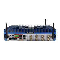
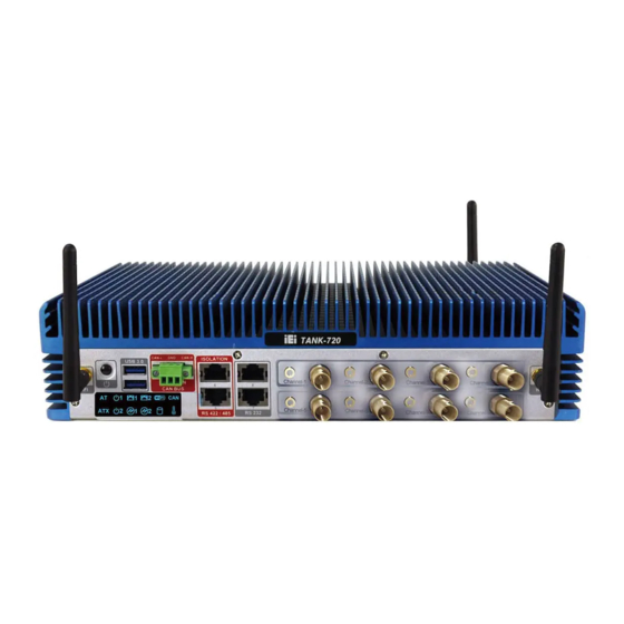
IEI Technology TANK-720 User Manual (118 pages)
High Performance Fanless Embedded System
Brand:
IEI Technology
| Category:
Industrial PC
| Size: 8 MB
Table of Contents
Table of Contents
6
Introduction
14
Overview
15
Model Variations
15
Figure 1-1: TANK-720
15
Table 1-1: TANK-720 Model Variations
15
Features
16
Technical Specifications
16
Connector Panel
18
Front Panel
18
Table 1-2: Technical Specifications
18
Rear Panel
19
Figure 1-2: TANK-720 Front Panel
19
Figure 1-3: TANK-720 Rear Panel
20
Led Indicators
21
Figure 1-4: TANK-720 LED Indicators
21
Dimensions
22
Figure 1-5: Physical Dimensions (MM)
22
2 Unpacking
23
Anti - Static Precautions
24
Unpacking Precautions
24
Unpacking Checklist
25
3 Installation
28
Installation Precautions
29
Hard Disk Drive (Hdd) Installation
29
Figure 3-1: Bottom Panel Retention Screws
30
Figure 3-2: HDD Bracket Retention Screws
30
Figure 3-3: HDD Installation
31
Figure 3-4: HDD Retention Screws
31
Pluggable Can- Bus Terminal Block Installation
32
Pluggable DC-I N Terminal Block Installation
32
Figure 3-5: Pluggable CAN-Bus Terminal Block Installation
32
Pluggable Remote Control Terminal Block Installation
33
Figure 3-6: Pluggable DC-In Terminal Block Installation
33
Sfp Module Installation
34
Figure 3-7: Pluggable Remote Control Terminal Block Installation
34
Figure 3-8: SFP Module Installation
34
So-DIMM Installation
35
Figure 3-9: SO-DIMM Socket
35
Mounting the System with Mounting Brackets
36
Figure 3-10: SO-DIMM Installation
36
External Peripheral Interface Connectors
37
Figure 3-11: Mounting Bracket Retention Screws
37
ACC Mode Switch
38
AT/ATX Power Mode Switch
38
Figure 3-12: ACC Mode Switch
38
Figure 3-13: AT/ATX Power Mode Switch
39
Audio Connector
40
Audio/Video Input Connectors
40
CAN-Bus Terminal Block
40
Figure 3-14: Audio Connector
40
Figure 3-15: CAN-Bus Terminal Block Pinouts
40
Digital I/O Connector
41
Figure 3-16: Digital I/O Connector Pinout Location
41
HDMI Connector
41
Table 3-1: Digital I/O Connector Pinouts
41
LAN Connectors
42
Table 3-2: HDMI Connector Pinouts
42
Figure 3-17: LAN Connection
43
Figure 3-18: RJ-45 Ethernet Connector
43
Table 3-3: LAN Pinouts
43
Figure 3-19: 4-Pin Terminal Block Pinout Location
44
Power Input, 4-Pin DIN Connector
44
Power Input, 4-Pin Terminal Block
44
Table 3-4: RJ-45 Ethernet Connector Leds
44
Table 3-5: 4-Pin Terminal Block Pinouts
44
Figure 3-20: Power Input Connector
45
Figure 3-21: Remote Control Terminal Block Pinout Location
45
Remote Control Terminal Block (for at Power Mode Only)
45
Table 3-6: Power Input Pinouts
45
Figure 3-22: RJ-45 RS-232 Serial Device Connection
46
RS-232 Serial Port Connectors
46
Figure 3-23: RJ-45 RS-232 Serial Port Pinout Location
47
Figure 3-24: DB-9 Connector Pinout Location
47
Table 3-7: RJ-45 RS-232 Serial Port Pinouts
47
Table 3-8: DB-9 Connector Pinouts
47
Figure 3-25: RJ-45 RS-422/485 Serial Device Connection
48
RS-422/485 Serial Port Connectors
48
Figure 3-26: RJ-45 RS-422/485 Serial Port Pinout Location
49
Figure 3-27: DB-9 Connector Pinout Location
49
Table 3-10: DB-9 Connector Pinouts
49
Table 3-9: RJ-45 RS-422/485 Serial Port Pinouts
49
Figure 3-28: Serial Device Connector
50
Serial Port Connectors
50
Figure 3-29: Serial Port Pinout Location
51
SFP Fiber Connectors
51
Table 3-11: Serial Port Pinouts
51
USB Connectors
51
Figure 3-30: USB Device Connection
52
Table 3-12: USB Port Pinouts
52
VGA Connector
52
Figure 3-31: VGA Connector
53
Figure 3-32: VGA Connector
53
Figure 3-33: Power Button
54
Powering O N /Off the System
54
Table 3-13: VGA Connector Pinouts
54
Redundant Power
55
Figure 3-34: Power Connectors
55
Acc on
56
Boot-Up
56
Figure 3-35: ACC On: at Mode
56
Figure 3-36: ACC On: ATX Mode
56
Figure 3-37: ACC On: Switch between PWR1 and PWR2
57
Figure 3-38: ACC On: Shutdown
57
Shutdown
57
Switch to Backup Power
57
Acc off
58
Boot-Up
58
Figure 3-39: ACC Off: at Mode
58
Figure 3-40: ACC Off: ATX Mode
58
Switch to Backup Power
59
Shutdown
59
Figure 3-41: ACC Off: Switch between PWR1 and PWR2
59
Figure 3-42: ACC Off: Shutdown
59
Bios
61
Introduction
62
Starting Setup
62
Using Setup
62
Getting Help
63
Unable to Reboot after Configuration Changes
63
4 Bios
62
BIOS Menu Bar
63
Table 4-1: BIOS Navigation Keys
63
BIOS Menu 1: Main
64
Main
64
Advanced
65
ACPI Settings
66
BIOS Menu 2: Advanced
66
BIOS Menu 3: ACPI Configuration
66
BIOS Menu 4: TPM Configuration
67
Trusted Computing
67
BIOS Menu 5: CPU Configuration
68
CPU Configuration
68
BIOS Menu 6: CPU Configuration
69
CPU Information
69
BIOS Menu 7: SATA Configuration
70
SATA Configuration
70
BIOS Menu 8: USB Configuration
72
USB Configuration
72
BIOS Menu 10: Serial Port N Configuration Menu
74
BIOS Menu 9: F81216 Second Super IO Configuration
74
Secondary Super IO Configuration
74
Serial Port N Configuration
74
BIOS Menu 11: Super IO Configuration
77
BIOS Menu 12: Serial Port N Configuration Menu
77
Serial Port N Configuration
77
Super IO Configuration
77
BIOS Menu 13: H/W Monitor
83
H/W Monitor
83
Serial Port Console Redirection
84
BIOS Menu 14: Serial Port Console Redirection
85
BIOS Menu 15: Iei Feature
86
Iei Feature
86
Chipset
87
BIOS Menu 16: Chipset
87
BIOS Menu 17: Northbridge Chipset Configuration
88
BIOS Menu 18: Graphics Configuration
88
Intel IGD SWSCI Opregion
88
North Bridge
88
South Bridge
89
BIOS Menu 19: Southbridge Chipset Configuration
90
BIOS Menu 20: ME Configuration
92
ME Configuration
92
BIOS Menu 21: Boot
93
Boot
93
Security
95
BIOS Menu 22: Security
96
Exit
97
BIOS Menu 23:Exit
97
A Regulatory Compliance
99
B Bios Options
105
C Safety Precautions
108
Safety Precautions
108
General Safety Precautions
109
C.1 S Afety P Recautions
109
Anti-Static Precautions
110
Product Disposal
111
Maintenance and Cleaning Precautions
111
Maintenance and Cleaning
111
Cleaning Tools
112
D Digital I/O Interface
113
Introduction
114
D.1 I Ntroduction
114
Assembly Language Sample
115
Assembly Language Sample 2
115
D.2 a Ssembly L Anguage S Ample 1
115
Advertisement
Advertisement
Related Products
IEI Technology TANK-870AI SERIES
IEI Technology TANK-GM45
IEI Technology TANK-880-Q370-i7R/8G/4A
IEI Technology TANK-870-Q170 Series
IEI Technology TANK-870-Q170i-i5/4G/2A-R10
IEI Technology TANK-870-Q170i-i5/4G/2B-R10
IEI Technology TANK-870-Q170i-i7/4G/4A-R10
IEI Technology TANK-870-Q170i-i7/4G/4B-R10
IEI Technology TANK-870-Q170i-i5/4G/2A
IEI Technology TANK-870-Q170i-i7/4G/2A
IEI Technology Categories
Motherboard
Touch Panel
Computer Hardware
Single board computers
Desktop
More IEI Technology Manuals
Login
Sign In
OR
Sign in with Facebook
Sign in with Google
Upload manual
Upload from disk
Upload from URL