Sun Microsystems SPARC Enterprise M4000 Installation Manual
Hide thumbs
Also See for SPARC Enterprise M4000:
- User manual (28 pages) ,
- Reference manual (506 pages) ,
- Administration manual (128 pages)
Chapters
Table of Contents

Related Manuals for Sun Microsystems SPARC Enterprise M4000


Summary of Contents for Sun Microsystems SPARC Enterprise M4000
-
Page 1: Installation Guide
Sun SPARC Enterprise ® M4000/M5000 Servers Installation Guide Sun Microsystems, Inc. www.sun.com Part No. 819-2211-12 November 2008, Revision A Submit comments about this document at: http://www.sun.com/hwdocs/feedback... - Page 2 Fujitsu Limited or Sun Microsystems, Inc., or any affiliate of either of them.
- Page 3 Aucune partie de ce produit, de ces technologies ou de ce document ne peut être reproduite sous quelque forme que ce soit, par quelque moyen que ce soit, sans l’autorisation écrite préalable de Fujitsu Limited et de Sun Microsystems, Inc., et de leurs éventuels bailleurs de licence.
-
Page 5: Table Of Contents
Contents Preface vii Installation Overview 1–1 Installation Workflow 1–1 Preparing to Install the Server 2–1 Safety Precautions 2–1 Before Installing the Server 2–2 2.2.1 Facility Power 2–2 2.2.2 Cable Connections 2–8 2.2.3 Checking the Installation Location 2–8 Tools and Equipment 2–9 Installing the Server 3–1 Checking Components 3–1 Connecting Input Power Cables 3–2... - Page 6 Connecting Additional Peripheral Devices 3–13 Connecting the Domains to the Network 4–1 Overview of Network Configuration 4–1 Connecting to the Network 4–1 Verifying the Network Connection 4–2 Verifying Operation by Running SunVTS Software 4–2 SPARC Enterprise M4000/M5000 Servers Installation Guide • November 2008...
-
Page 7: Preface
Enterprise M4000/M5000 Servers Installation Guide describes how to install and set up the Sun SPARC Enterprise M4000/M5000 midrange servers. References herein to the SPARC Enterprise M4000 server are references to the Sun SPARC Enterprise M4000 server. References herein to the SPARC Enterprise M5000 server are references to the Sun SPARC Enterprise M5000 server. - Page 8 This document might not contain information about basic UNIX commands and procedures. Refer to the following for this information: Software documentation that you received with your system ■ Solaris™ Operating System (Solaris OS) documentation, at: ■ http://docs.sun.com viii SPARC Enterprise M4000/M5000 Servers Service Manual • November 2008...
-
Page 9: Typographic Conventions
Shell Prompts Shell Prompt C shell machine-name% C shell superuser machine-name# Bourne shell and Korn shell Bourne shell and Korn shell superuser XSCF Shell XSCF> Typographic Conventions Typeface Meaning Examples The names of commands, files, Edit your.login file. AaBbCc123 and directories; on-screen Use ls -a to list all files. - Page 10 Reference Manual Software Sun SPARC Enterprise M4000/M5000/M8000/M9000 Online Administration Servers Dynamic Reconfiguration (DR) User’s Guide HTML Software Sun SPARC Enterprise M4000/M5000/M8000/M9000 Online Administration Servers Capacity on Demand (COD) User’s Guide HTML x SPARC Enterprise M4000/M5000 Servers Service Manual • November 2008...
-
Page 11: Sun Welcomes Your Comments
Sun management Center (Sun MC) Software Supplement Online Administration HTML Glossary Sun SPARC Enterprise Online M3000/M4000/M5000/M8000/M9000 Servers Glossary HTML Hardware/Software Sun SPARC Enterprise M4000/M5000 Product Notes HTML Online Documentation, Support, and Training Sun Function Documentation http://www.sun.com/documentation/ Support http://www.sun.com/support/ Training http://www.sun.com/training/... - Page 12 Please include the title and part number of your document with your feedback: SPARC Enterprise M4000/M5000 Servers Installation Guide, part number 819-2211-12 xii SPARC Enterprise M4000/M5000 Servers Service Manual • November 2008...
-
Page 13: Installation Overview
C H A P T E R Installation Overview This chapter provides the process for installing the servers. Installation Workflow Installing a server requires the steps in FIGURE 1-1... -
Page 14: Power Supply
“Powering On the Server” on page 3-8 Installing additional peripheral devices “Connecting Additional Peripheral Devices” on page 3- Environmental Setting up the network Setup “Overview of Network Configuration” on page 4-1 Workflow Required for Installation FIGURE 1-1 SPARC Enterprise M4000/M5000 Servers Installation Guide • November 2008... -
Page 15: Preparing To Install The Server
C H A P T E R Preparing to Install the Server This chapter describes the items you are required to check, the environmental requirements for installation, installation areas, and other related matters. It contains the following sections: “Safety Precautions” on page 2-1 ■... -
Page 16: Before Installing The Server
Before installing the server, you must know the system configuration and obtain all the prerequisite information for system installation. For instructions, refer to the SPARC Enterprise M4000/M5000 Servers Site Planning Guide and the guide that came with the rack. 2.2.1... - Page 17 Electrical Specifications for the SPARC Enterprise M4000 Server TABLE 2-1 Parameter Value Number of power cords 2 (1 power cord per power supply unit) Redundancy 1 + 1 redundant. Second power supply is redundant at 200 VAC Input current Voltage range 100–127 VAC...
-
Page 18: Facility Power Requirements And Characteristics
PSU#0 PSU#1 Circuit breaker SPARC Enterprise M4000 Server With Redundant PSU Connection FIGURE 2-1 SPARC Enterprise M4000/M5000 Servers Installation Guide • November 2008... - Page 19 PSU#1 PSU#2 PSU#3 PSU#0 Circuit breaker SPARC Enterprise M5000 Server With Redundant PSU Connection FIGURE 2-2 For a dual-power feed connection, connect the individual power cords separately to each AC power supply system. Chapter 2 Preparing to Install the Server...
- Page 20 PSU#0 PSU#1 Circuit breaker Circuit breaker SPARC Enterprise M4000 Server With Dual-power Feed Connection FIGURE 2-3 SPARC Enterprise M4000/M5000 Servers Installation Guide • November 2008...
- Page 21 PSU#0 PSU#1 PSU#2 PSU#3 Circuit breaker Circuit breaker SPARC Enterprise M5000 Server With Dual-power Feed Connection FIGURE 2-4 Chapter 2 Preparing to Install the Server...
-
Page 22: Cable Connections
NEMA L6-20 250V 20A Connector Rest of the world IEC60309 16A 250V, 3PIN with IEC60320 Refer to the SPARC Enterprise M4000/M5000 Servers Site Planning Guide for electronic specifications of the midrange servers. 2.2.3 Checking the Installation Location When installing the server, consider not only the device sizes but also the sizes of the required service areas (maintenance areas). -
Page 23: Tools And Equipment
Tools and Equipment The following sections list the tools that are required to install the servers. The following tools are required to install the servers: Screwdriver, Phillips No. 2 ■ Antistatic wrist strap ■ Antistatic mat ■ Ethernet cable of category 5 or higher ■... - Page 24 2-10 SPARC Enterprise M4000/M5000 Servers Installation Guide • November 2008...
-
Page 25: Installing The Server
C H A P T E R Installing the Server This chapter describes how to install the server. It contains the following sections: “Checking Components” on page 3-1 ■ “Connecting Input Power Cords” on page 3-2 ■ “Connecting the Administration Console” on page 3-4 ■... -
Page 26: Connecting Input Power Cords
3. Make certain the power cords are tightly fastened. Note – The power cords and infiniband cables should hang loosely in a service loop behind the server or the cable management arm may not be able to fully retract. SPARC Enterprise M4000/M5000 Servers Service Manual • November 2008... -
Page 27: Connecting A Ups Unit
3.2.1 Connecting a UPS Unit An uninterruptible power supply (UPS) unit is used to provide a stable supply of power to the system in the event of a power failure or an extensive power interruption. A UPS with an UPC interface can be connected to the UPC ports on the eXtended System Control facility unit (XSCFU or XSCF Unit) ( ) so that FIGURE 3-2... -
Page 28: Verifying The Power Input Connections Before Applying Power
Have the site electrician verify that the input power source fulfills the power requirements. Refer to the SPARC Enterprise M4000/M5000 Servers Site Planning Guide for input power requirements. Note – The server end of the power cords should have been connected prior to shipment (for servers preinstalled in an equipment rack) or when the server was mounted in the equipment cabinet. - Page 29 Ports on XSCF Unit (SPARC Enterprise M5000 Shown) FIGURE 3-2 Location Number Component RCI Port Serial Port USB port LAN 1 (Ethernet#1) LAN 0 (Ethernet#0) UPC#1 UPC#0 Chapter 3 Installing the Server...
-
Page 30: Connecting The Console
Refer to the manual that shipped with the input power source for instructions. 5. Watch the administration console for error messages as the XSCF Unit powers on. Appendix B for fault installation information. SPARC Enterprise M4000/M5000 Servers Service Manual • November 2008... - Page 31 6. Confirm that the XSCF STANDBY LED (green) on the operator panel is lit. Note – Step 8 must be performed within a minute of Step 7 or the login certification will time out. 7. When the login prompt appears, enter default for the login name: login: default 8.
-
Page 32: Initializing The Xscf Unit
This section explains how to power on the server the first time. 1. Set the key on the operator panel to the Service position. 2. From the XSCF Shell, type the console command: XSCF> console -d 0 SPARC Enterprise M4000/M5000 Servers Service Manual • November 2008... -
Page 33: Verifying The Configuration
3. Confirm that the XSCF STANDBY LED (green) on the operator panel is lit. 4. Push the power switch on the operator panel to power on the server. The server starts and begins a self-diagnosis. Watch the initial system administration console for error messages during the boot process. - Page 34 | FANBP_C FAN_A +-----------------------------------+------------+ XSCF> See the “Using the showhardconf Command” on page B-2 for details. 3. Use the console command to go to the ok prompt. XSCF> console -d 0 3-10 SPARC Enterprise M4000/M5000 Servers Service Manual • November 2008...
- Page 35 4. From the ok prompt, use the probe-scsi-all command to confirm that the storage devices are installed. ok probe-scsi-all /pci@0,600000/pci@0/pci@8/pci@0/scsi@1 MPT Version 1.05, Firmware Version 1.07.00.00 Target 0 Unit 0 Disk SEAGATE ST973401LSUN72G 0556 143374738 Blocks, 73 GB SASAddress 5000c5000092beb9 PhyNum 0 Target 1 Unit 0...
- Page 36 If the configuration is incorrect contact your sales representative. 7. Boot the Solaris™ operating system (Solaris OS) and configure the domains. Refer to the Solaris software documentation for details. 3-12 SPARC Enterprise M4000/M5000 Servers Service Manual • November 2008...
-
Page 37: Checking The Dual-Power Feed
3.4.2 Checking the Dual-Power Feed If the dual-power feed option is used, follow the procedure below to confirm that the system can operate even if one power feed is stopped. Note – Dual-Power Feed mode cannot be used with 100V power. 1. - Page 38 3-14 SPARC Enterprise M4000/M5000 Servers Service Manual • November 2008...
-
Page 39: Connecting The Domains To The Network
C H A P T E R Connecting the Domains to the Network This chapter discusses how to establish a network for the servers. It contains the following sections: “Overview of Network Configuration” on page 4-1 ■ “Connecting to the Network” on page 4-1 ■... -
Page 40: Verifying The Network Connection
Refer to the Solaris software documentation for information on starting the system from each domain and configuring the domains for the network. Refer to the SunVTS User’s Guide for information on installing and use of the SunVTS software. SPARC Enterprise M4000/M5000 Servers Service Manual • November 2008... -
Page 41: System Views
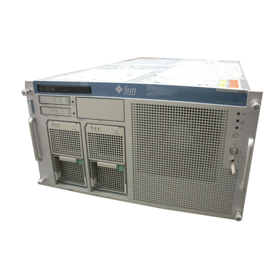
A P P E N D I X System Views Appendix A provides views of the systems. This appendix has the following sections: Section A.1, “SPARC Enterprise M4000 Server Views” on page A-2 ■ Section A.2, “SPARC Enterprise M5000 Server Views” on page A-5 ■... - Page 42 SPARC Enterprise M4000 Server Views shows the SPARC Enterprise M4000 server. FIGURE A-1 SPARC Enterprise M4000 Server Component Locations FIGURE A-1 SPARC Enterprise M4000/M5000 Servers Service Manual • November 2008...
- Page 43 Location Number Component 60-mm fan (FAN_B#0) 60-mm fan (FAN_B#1) Top cover Fan cover Backplane Unit (BPU_A - includes IOBP, Power distribution board) 172-mm fan backplane (FANBP_A) 60-mm fan backplane (FANBP_B) Tape drive backplane (TAPEBP) Hard disk drive backplane (HDDBP#0) CD-RW/DVD-RW backplane (DVDBP_A) CD-RW/DVD-RW drive unit (DVDU) Hard disk drive (HDD#1) Hard disk drive (HDD#0)
- Page 44 PCI slot (IOU#0 PCI#4) eXtended System Control facility unit (XSCFU) I/O Unit (IOU#0) DC-DC Converter Riser (DDCR IOU#0 Not shown) DC-DC Converter (DDC_B on DDCR on IOU#0) DC-DC Converter (DDC_A IOU#0 Not shown) SPARC Enterprise M4000/M5000 Servers Service Manual • November 2008...
- Page 45 SPARC Enterprise M5000 Server Views shows the SPARC Enterprise M5000 server. FIGURE A-2 Appendix A System Views...
- Page 46 30 31 23 24 25 26 32 33 34 35 SPARC Enterprise M5000 Server Component Locations FIGURE A-2 SPARC Enterprise M4000/M5000 Servers Service Manual • November 2008...
- Page 47 Location Number Component Top cover CPU module (CPUM#0) CPU module (CPUM#1) CPU module (CPUM#2) CPU module (CPUM#3) 172-mm fan (FAN_A#1) 172-mm fan (FAN_A#0) 172-mm fan (FAN_A#3) 172-mm fan (FAN_A#2) Backplane unit (BPU_B - includes IOBP, Power distribution board, bus bar) 172-mm fan backplane (FANBP_C) CD-RW/DVD-RW backplane (DVDBP_B) Tape drive backplane (TAPEBP)
- Page 48 DC-DC Converter (DDC_A#2) DC-DC Converter (DDC_A#3) DC-DC Converter (DDC_B#0) DC-DC Converter (DDC_B#1) Motherboard unit (MBU_B) Motherboard carriage Memory board (MEMB#7) Memory board (MEMB#6) Memory board (MEMB#5) Memory board (MEMB#4) Memory Board (MEMB#3) SPARC Enterprise M4000/M5000 Servers Service Manual • November 2008...
- Page 49 Location Number Component Memory board (MEMB#2) Memory board (MEMB#1) Memory board (MEMB#0) Appendix A System Views...
- Page 50 SPARC Enterprise M4000 Server operator panel. FIGURE A-3 SPARC Enterprise M4000 Server Operator Panel FIGURE A-3 Location Number Component POWER LED XSCF STANDBY LED CHECK LED Power switch Mode switch (keyswitch) Antistatic ground socket A-10 SPARC Enterprise M4000/M5000 Servers Service Manual • November 2008...
- Page 51 shows the SPARC Enterprise M5000 Server operator panel. FIGURE A-4 SPARC Enterprise M5000 Server Operator Panel FIGURE A-4 Location Number Component POWER LED XSCF STANDBYy LED CHECK LED Power switch Mode switch (keyswitch) Antistatic ground socket Appendix A System Views A-11...
- Page 52 The Service setting: • Service should be provided at this position. • Power on and off is available with Power switch. • The key cannot be pulled out at this position. A-12 SPARC Enterprise M4000/M5000 Servers Service Manual • November 2008...
-
Page 53: Fault Isolation
“can’t locate boot device” Refer to the “Before Using Solaris 10” and “Checklists for Installation and Bug ■ Information” in the Solaris 10 Release and Installation Collection. Refer to the SPARC Enterprise M4000/M5000 Servers Service Manual for LED ■ status. - Page 54 The showhardconf command displays information about each FRU. The following information is displayed: Current configuration and status ■ Number of installed FRUs ■ Domain information ■ IOBOX information ■ Name properties of PCI cards ■ SPARC Enterprise M4000/M5000 Servers Service Manual • November 2008...
- Page 55 An example of the showhardconf output. XSCF> showhardconf SPARC Enterprise M5000; + Serial:BE80601000; Operator_Panel_Switch:Service; + Power_Supply_System:Single; SCF-ID:XSCF#0; + System_Power:On; Domain#0 Domain_Status:Powered Off; MBU_B Status:Normal; Ver:0101h; Serial: + FRU-Part-Number:CF00541-0478 01 /541-0478-01 ; + Memory_Size:64 GB; CPUM#0-CHIP#0 Status:Normal; Ver:0201h; Serial:PP0629L068 ; + FRU-Part-Number:CF00375-3477 50 /375-3477-50 ; + Freq:2.150 GHz;...
- Page 56 + Power_Status:Off; AC:200 V; FANBP_C Status:Normal; Ver:0101h; Serial:7867000053: + FRU-Part-Number:CF00541-0848 01 /541-0848-01 ; FAN_A#0 Status:Normal; FAN_A#1 Status:Normal; FAN_A#2 Status:Normal; FAN_A#3 Status:Normal; XSCF> Refer to the showhardconf man page for more information. SPARC Enterprise M4000/M5000 Servers Service Manual • November 2008...
-
Page 57: Using The Showlogs Command
B.2.2 Using the showlogs Command The showlogs command displays the contents of a specified log in order of timestamp starting with the oldest date. The showlogs command displays the following logs: error log ■ power log ■ event log ■ temperature and humidity record ■... -
Page 58: Using The Showstatus Command
You can obtain more detail by using the -V option, as shown in the following example. # fmdump -V -u 0ee65618-2218-4997-c0dc-b5c410ed8ec2 TIME UUID SUNW-MSG-ID Nov 02 10:04:15.4911 0ee65618-2218-4997-c0dc-b5c410ed8ec2 SUN4-8000-0Y 100% fault.io.fire.asic FRU: hc://product-id=SUNW,A70/motherboard=0 rsrc: hc:///motherboard=0/hostbridge=0/pciexrc=0 SPARC Enterprise M4000/M5000 Servers Service Manual • November 2008... -
Page 59: Using The Fmadm Faulty Command
At least three lines of new output are delivered to the user with the -V option: The first line is a summary of information you have seen before in the console ■ message but includes the timestamp, the UUID, and the Message-ID. The second line is a declaration of the certainty of the diagnosis. -
Page 60: Using The Fmstat Command
“solve” the cause for the failure. An example of the fmstat output. XSCF> fmstat module ev_recv ev_acpt wait svc_t open solve memsz bufsz 3.3M event-transport 6.4K faultevent-post fmd-self-diagnosis 352.1 iox_agent reagent sysevent-transport 0.0 8700.4 syslog-msgs XSCF> SPARC Enterprise M4000/M5000 Servers Service Manual • November 2008... - Page 61 Traditional Solaris Diagnostic Commands These superuser commands can help you determine if you have issues in your server, in the network, or within another server that you are networking with. The following commands are detailed in this section. “Using the iostat Command” on page B-9 ■...
- Page 62 Product: ST973401LSUN72G Revision: 0556 Serial No: 0521104V3V Size: 73.40GB <73400057856 bytes> Media Error: 0 Device Not Ready: 0 No Device: 0 Recoverable: 0 Illegal Request: 0 Predictive Failure Analysis: 0 B-10 SPARC Enterprise M4000/M5000 Servers Service Manual • November 2008...
- Page 63 B.3.2 Using the prtdiag Command The prtdiag command displays configuration and diagnostic information. The diagnostic information identifies any failed component. The prtdiag command is located in the /usr/platform/platform-name/sbin/ directory. Note – The prtdiag command might indicate a slot number different than that identified elsewhere in this document.
- Page 64 SUNW,pci-ce SUNW,qlc QLE2462 SUNW,qlc QLE2462 ==================== Hardware Revisions ==================== System PROM revisions: ---------------------- OBP 4.x.build_103***PROTOTYPE BUILD*** 2006/08/01 02:06 =================== Environmental Status =================== Mode switch is in UNLOCK mode B-12 SPARC Enterprise M4000/M5000 Servers Service Manual • November 2008...
- Page 65 B.3.3 Using the prtconf Command Similar to the show-devs command run at the ok prompt, the prtconf command displays the devices that are configured. The prtconf command identifies hardware that is recognized by the Solaris OS. If hardware is not suspected of being bad yet software applications are having trouble with the hardware, the prtconf command can indicate if the Solaris software recognizes the hardware, and if a driver for the hardware is loaded.
- Page 66 SUNW,asr (driver not attached) ufs-file-system (driver not attached) chosen (driver not attached) openprom (driver not attached) client-services (driver not attached) options, instance #0 aliases (driver not attached) . . . B-14 SPARC Enterprise M4000/M5000 Servers Service Manual • November 2008...
-
Page 67: Using The Netstat Command
B.3.4 Using the netstat Command The netstat command displays the network status. B.3.4.1 Options describes options for the netstat command and how those options can TABLE B-6 help troubleshooting. Options for netstat TABLE B-6 Option Description How It Can Help Displays the interface state, Provides a quick overview of the network status. - Page 68 Displays the route the probe Indicates probe packet route and number of hops. -svR packet followed in one-second Comparing multiple routes can identify bottlenecks. intervals. B-16 SPARC Enterprise M4000/M5000 Servers Service Manual • November 2008...
- Page 69 The following example shows output for the ping -s command. # ping -s san-ff2-17-a PING san-ff2-17-a: 56 data bytes 64 bytes from san-ff2-17-a (10.1.67.31): icmp_seq=0. time=0.427 ms 64 bytes from san-ff2-17-a (10.1.67.31): icmp_seq=1. time=0.194 ms ----san-ff2-17-a PING Statistics---- 2 packets transmitted, 2 packets received, 0% packet loss round-trip (ms) min/avg/max/stddev = 0.172/0.256/0.427/0.102 Appendix B Fault Isolation...
- Page 70 0:00 ps 101025 pts/3 0:00 sh Note – When using with the option, the column headings are printed so that the sort value in the first column is equal to zero. B-18 SPARC Enterprise M4000/M5000 Servers Service Manual • November 2008...
- Page 71 B.3.7 Using the prstat Command The prstat utility iteratively examines all active processes and reports statistics based on the selected output mode and sort order. The prstat command provides output similar to the ps command. B.3.7.1 Options describes options for the prstat command and how those options can TABLE B-9 help troubleshooting.
- Page 72 B-20 SPARC Enterprise M4000/M5000 Servers Service Manual • November 2008...
Need help?
Do you have a question about the SPARC Enterprise M4000 and is the answer not in the manual?
Questions and answers