YASKAWA VS mini J7 Series Instruction Manual
Compact general-purpose inverter
Hide thumbs
Also See for VS mini J7 Series:
- Instruction manual (119 pages) ,
- Replacement instructions manual (16 pages) ,
- Connection manual (64 pages)
Table of Contents

Related Manuals for YASKAWA VS mini J7 Series


Summary of Contents for YASKAWA VS mini J7 Series
- Page 1 YASKAWA VS mini J7 Series INSTRUCTION MANUAL COMPACT GENERAL-PURPOSE INVERTER Upon receipt of the product and prior to initial operation, read these instructions thoroughly and retain them for future reference. YASKAWA MANUAL NO. TOE-S606-12.1G...
-
Page 2: General Precautions
• To order a copy of this manual, or if your copy has been damaged or lost, contact your Yaskawa representative. • Yaskawa is not responsible for any modification of the product made by the user, since that will void the guarantee. -
Page 3: Notation For Safety Precautions
NOTATION FOR SAFETY PRECAUTIONS Read this instruction manual thoroughly before installation, operation, mainte- nance, or inspection of the VS mini. In this manual, safety precautions are classi- fied as either warnings or cautions and are indicated as shown below. WARNING Indicates a potentially hazardous situation which, if not avoided, may result in death or serious injury. - Page 4 PRECAUTIONS FOR UL/cUL MARKING • Do not connect or disconnect wiring, or perform signal checks while the power supply is turned ON. • The Inverter internal capacitor is still charged even after the power supply is turned OFF. To prevent electric shock, disconnect all power before ser- vicing the Inverter, and then wait at least one minute after the power sup- ply is disconnected.
-
Page 5: Receiving The Product
RECEIVING THE PRODUCT CAUTION (Ref. page) • Do not install or operate any Inverter that is damaged or has missing parts. Failure to observe this caution may result in injury or equipment damage. MOUNTING CAUTION (Ref. page) • Lift the Inverter by the heatsinks. When moving the Inverter, never lift it by the plastic case or the terminal cover. - Page 6 WIRING WARNING (Ref. page) • Only begin wiring after verifying that the power supply is turned OFF. Failure to observe this warning may result in an elec- tric shock or a fire. • Wiring should be performed only by qualified personnel.
- Page 7 CAUTION (Ref. page) • Verify that the Inverter rated voltage coincides with the AC power supply voltage. Failure to observe this caution may result in personal injury or a fire. • Do not perform a withstand voltage test on the Inverter.
- Page 8 OPERATION WARNING (Ref. page) • Only turn ON the input power supply after con- firming that the front cover, top cover, and bot- tom cover are in place. Do not remove the covers while current is flowing. Failure to observe this warning may result in an elec- tric shock.
- Page 9 WARNING (Ref. page) • If an alarm is reset with the operation signal ON, the Inverter will restart automatically. Reset an alarm only after verifying that the operation sig- nal is OFF. Failure to observe this warning may result in injury. •...
- Page 10 CAUTION • All the constants set in the Inverter have been preset at the factory. Do not change the settings unnecessarily. The Inverter may be damaged. MAINTENANCE AND INSPECTION WARNING (Ref. page) • Never touch high-voltage terminals on the Inverter. Failure to observe this warning may result in an elec- tric shock.
- Page 11 CAUTION (Ref. page) • The control PCB employs CMOS ICs. Do not touch the CMOS elements. They are easily damaged by static electricity. • Do not connect or disconnect wires, connectors, or the cooling fan while power is applied to the circuit.
-
Page 12: Warning Label
WARNING LABEL A warning label is provided on the front cover of the Inverter, as shown below. Follow the warnings when handling the Inverter. Plastic Case Qualification Mark Nameplate Status Indicators Warning Display... - Page 13 English and French Warning Labels Warning Labels at End of Instruction Manual A Japanese warning label is attached when the VS mini is shipped. If a English or French label is required, attach the warning label at the end of the Instruction Manual over the Japa- nese warning label.
-
Page 14: Warranty Information
Repairs If a Yaskawa product is found to be defective due to Yaskawa workman- ship or materials and the defect occurs during the warranty period, Yaskawa will provide a replacement, repair the defective product, and provide shipping to and from the site free of charge. - Page 15 Exceptions Any inconvenience to the customer or damage to non-Yaskawa products due to Yaskawa's defective products whether within or outside the war- ranty period are NOT covered by this warranty. RESTRICTIONS • The VS mini was not designed or manufactured for use in devices or sys- tems that may directly affect or threaten human lives or health.
-
Page 16: Table Of Contents
CONTENTS NOTATION FOR SAFETY PRECAUTIONS - - - - - - 2 1. Receiving the Product - - - - - - - - - - - - - - - - - - - 19 ■ Checking the Nameplate - - - - - - - - - - - - - - - - - - - - - - - - - - - 19 2. - Page 17 ■ Constant Setup and Initialization - - - - - - - - - - - - - - - - - - - - - - 44 Constant Selection/Initialization (n01) - - - - - - - - - - - - - - - - - - 44 ■...
- Page 18 ■ Selecting the Stopping Method- - - - - - - - - - - - - - - - - - - - - - - 67 Stopping Method Selection (n04) - - - - - - - - - - - - - - - - - - - - - 67 Applying DC Injection Braking - - - - - - - - - - - - - - - - - - - - - - - 68 ■...
- Page 19 9. Specifications - - - - - - - - - - - - - - - - - - - - - - - 106 ■ Standard Specifications (200 V Class) - - - - - - - - - - - - - - - - - 106 ■...
-
Page 20: Receiving The Product
C I M R J 7 A A 2 0 P 1 Applicable maximum motor output Inverter 0.1 kW 0.2 kW VS mini J7 Series 0.4 kW 0.75 kW No. Type 1.5 kW With Digital Operator (with potentiometer) 2.2 kW Without Digital Operator 3.0 kW... -
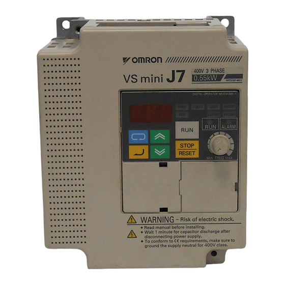
Page 21: Identifying The Parts
2. Identifying the Parts Digital Operator Front Cover Wiring Holes for Control Circuit Option Digital Operator (with potentiometer) Cover Used for setting or changing constants. Bottom Cover Frequency can be set using potentiometer. Ground Terminal Heatsink Fan Cover Wiring Holes for Main Circuit Cooling Fan Digital Operator (without potentiometer) -
Page 22: Mounting
3. Mounting 3. Mounting Choosing a Location to Mount the Inverter Be sure the Inverter is protected from the following conditions. • Extreme cold and heat. Use only within the specified ambient tem- perature range: −10 to 50°C • Rain and moisture •... -
Page 23: Mounting Dimensions
Mounting Dimensions To mount the VS mini, the dimensions shown below are required. 30 mm 30 mm or more or more... -
Page 24: Mounting/Removing Components
3. Mounting Mounting/Removing Components Removing and Mounting the Digital Operator and Covers • Removing the Front Cover Use a screwdriver to loosen the screw on the front cover and then remove it in direction 1. Then press the right and left sides in direction 2 and lift the front cover in direction 3. -
Page 25: Wiring
4. Wiring Wiring Instructions 1. Always connect the power supply to the power input terminals R/L1, S/L2, and T/L3 (R/L1, S/L2 for single-phase power) via a molded- case circuit breaker (MCCB) or a fuse. Never connect the power supply to terminals U/T1, V/T2, W/T3, −, +1, or +2. Refer to page 119 for recommended peripheral devices. -
Page 26: Wire And Terminal Screw Sizes
4. Wiring 9. Closed-loop connectors should be used when wiring to the main cir- cuit terminals. 10.Voltage drop should be considered when determining the wire size. Voltage drop can be calculated using the following equation: Phase-to-phase voltage drop (V) × wire resistance (Ω/km) × wiring distance (m) × current (A) ×... - Page 27 2. Main Circuits 200 V Class 3-phase Input Inverters Model Terminal Screws Tightening Wires Symbols Torque Applicable Size Recommended Type Size CIMR- R/L1, S/L2, T/L3, M3.5 0.8 to 1.0 0.75 to 2 18 to 14 600 V vinyl- J7∗A -, +1, +2 sheathed or 20P1 equivalent...
- Page 28 4. Wiring 200 V Class Single-phase Input Inverters Model Terminal Screws Tightening Wires Symbols Torque Applicable Size Recommended Type Size CIMR- R/L1, S/L2, T/L3, M3.5 0.8 to 1.0 0.75 to 2 18 to 14 600 V vinyl- J7∗A -, +1, +2 sheathed or B0P1 equivalent...
- Page 29 400 V Class 3-phase Input Inverters Model Terminal Sym- Screws Tightening Wires bols Torque Applicable Size Recommended Type Size CIMR- R/L1, S/L2, T/L3, M3.5 0.8 to 1.0 2 to 5.5 14 to 10 600 V vinyl- J7∗A -, +1, +2, U/T1, sheathed or 40P2 V/T2, W/T3...
-
Page 30: Wiring The Main Circuits
4. Wiring Wiring the Main Circuits R S T [Example of 3-phase, 200 V Class, 1.5 kW Inverters] MCCB or Leakage Breaker Ground • Main Circuit Input Power Supply Always connect the power supply line to input terminals R/L1, S/L2, and T/L3 (R/L1, S/ L2 for single-phase Inverters). - Page 31 • Inverter Output Connect the motor terminals to U/T1, V/T2, and W/T3. • Wiring the Main Circuit Terminals Pass the cables through wiring hole to connect them. Always mount the cover in its origi- nal position. Connect with a Phillips screwdriver.
-
Page 32: Wiring The Control Circuits
4. Wiring Wiring the Control Circuits Only basic insulation is provided for the control circuit terminals. Additional insulation may be necessary in the end product. • Control Circuit Terminals Pass the cable through wiring hole to connect it. Always mount the cover in its original position. -
Page 33: Wiring Inspection
Open the front cover and verify that the strip length is 5.5 mm. Scale Wiring Inspection After completing wiring, check the following. • Wiring is proper. • Wire clippings or screws are not left in the Inverter. • Screws are securely tightened. •... -
Page 34: Operating The Inverter
5. Operating the Inverter 5. Operating the Inverter Test Run The Inverter operates when a frequency (speed) is set. There are three operating modes for the VS mini: 1. RUN command from the Digital Operator (potentiometer/digital set- ting) 2. RUN command from the control circuit terminals 3. -
Page 35: Operation Check Points
Operation Steps Operator Function Status Display Indicators Indicators 1. Turn the potentiometer fully counterclock- FREF FREF wise, and then turn the power ON. ALARM 2. F/R will flash. Select FWD or REV RUN using the keys. (Forward) ALARM Never select REV when reverse run is prohibited. -
Page 36: Operating The Digital Operator
5. Operating the Inverter Operating the Digital Operator All functions of the VS mini are set using the Digital Operator. Below are descriptions of the display and keypad sections. Digital Operator Status indicators Function indicators Indicators switch to another function each Data display section time DSPL is pressed. -
Page 37: Description Of Status Indicators
Description of Status Indicators There are two status indicators on the middle right section of the face of the VS mini. The combinations of these indicators indicate the status of the Inverter (ON, flashing, and OFF). RUN indicator and status indica- tor on button have the same function. - Page 38 5. Operating the Inverter The fault can be reset by turning ON the FAULT RESET sig- NOTE nal (or by pressing the key on the Digital Operator) with the operation signal OFF, or by turning OFF the power supply. If the operation signal is ON, the fault cannot be reset using the FAULT RESET signal.
-
Page 39: Function Indicator Description
Function Indicator Description By pressing on the Digital Operator, each of the function indi- cators can be selected. The following flowchart describes each function indicator. Power ON Frequency reference setting/monitoring (Hz) Sets VS mini operating speed. Output frequency monitoring (Hz) Displays frequency that VS mini is If the VS mini currently outputting. -
Page 40: Mntr Multi-Function Monitoring
5. Operating the Inverter If the VS mini is stopped after it has LOCAL/REMOTE Selection changed to any of This function switches the operation; operation using the digital operator including frequency these modes during setting with potentiometer, or that using the input operation, it changes terminals, or through communications Setting can be changed using the... -
Page 41: Input/Output Terminal Status
Monitoring The following items can be monitored using U constants. Constant Name Unit Description Frequency Reference Frequency reference can be monitored. (Same as (FREF) FREF) Output Frequency Output frequency can be monitored. (FOUT) (Same as FOUT) Output Current (IOUT) Output current can be monitored. (Same as IOUT) Output Voltage Output voltage can be monitored. -
Page 42: Simple Data Setting
5. Operating the Inverter Fault History Display Method Fault description is displayed when U09 is selected. (Example) : Fault description “---” is displayed if there is no fault. (Refer to page 97 for details.) Clearing the Fault History Set constant n01 to 6 to clear the fault history. Set data returns to its ini- tial value after 6 is set. - Page 43 Following is an example in which the function LEDs are used to set fre- quency reference, acceleration time, deceleration time, and motor direc- tion. Operation Steps Operator Function Status Display Indicators Indicators 1. Turn ON the power supply. FREF ALARM 2.
-
Page 44: Programming Features
6. Programming Features 6. Programming Features Factory settings of the constants are shaded in the tables. After wiring is complete, be sure to make the following settings before oper- ation. Hardware Make the following settings before the Inverter is turned ON. Item Ref. -
Page 45: Constant Setup And Initialization
Constant Setup and Initialization Constant Selection/Initialization (n01) The following table lists the data that can be set or read when n01 is set. Unused constants between n01 and n79 are not displayed. n01 Setting Constant That Can Be Set Constant That Can Be Referenced n01 to n79 n01 to n79 n01 to n79... -
Page 46: Selecting V/F Pattern
6. Programming Features 4. If the Frequency Reference Lower Limit (n31) ≤ Fre- quency Reference Upper Limit (n30) 5. If the Motor Rated Current (n32) ≤ 120% of Inverter rated current Selecting V/f Pattern Adjusting Torque According to Application Adjust motor torque by using the V/f pattern and full-range automatic torque boost settings. - Page 47 Typical Setting of the V/f Pattern Set the V/f pattern according to the application as described below. For 400-V Class Inverters, the voltage values (n10, n13, and n15) should be doubled. When running at a frequency exceeding 50/60 Hz, change the Maximum Output Frequency (n09).
- Page 48 6. Programming Features When operating with frequency larger than 60 Hz/50 Hz, change only max. output frequency (n09). Constant Output or Constant Variable Output Torque =200 V Base Point n11=60 Hz n09=90 Hz Full-range Automatic Torque Boost The motor torque requirement changes according to load conditions. The full-range automatic torque boost adjusts the voltage of the V/f pat- tern according to requirements.
-
Page 49: Switching Local/Remote Mode
Switching LOCAL/REMOTE Mode The following functions can be selected by switching LOCAL or REMOTE mode. To select the RUN/STOP command or frequency ref- erence, change the mode in advance depending on the following appli- cations. • LOCAL mode: Enables the Digital Operator for RUN/STOP com- mands and FWD/REV RUN commands. -
Page 50: Selecting Run/Stop Commands
6. Programming Features Selecting RUN/STOP Commands Refer to Switching LOCAL/REMOTE Mode (page 48) to select either the LOCAL mode or REMOTE mode. The operation method (RUN/STOP commands, FWD/REV RUN com- mands) can be selected using the following method. LOCAL Mode When Lo (local mode) is selected for Digital Operator mode, or when the LOCAL/REMOTE switching function is set and the input terminals are turned ON, run operation is enabled by the... -
Page 51: Operating (Run/Stop Commands) Using Communications (When Option Card Is Installed)
Operating (RUN/STOP Commands) Using Communications (When Option Card is Installed) Setting constant n02 to 2 in REMOTE mode enables using RUN/STOP commands via MEMOBUS communications. For commands using MEMOBUS communications, refer to page 83. Selecting Frequency Reference Frequency reference can be selected by the following methods. Setting by Operator Select REMOTE or LOCAL mode in advance. -
Page 52: Setting Operation Conditions
6. Programming Features =6: Enables communications. (Refer to page 83.) Example of frequency reference by voltage signal n03 : 2 (Factory setting: 0) FS (Frequency Setting Power +12 V 20 mA) (0 to +10 V) Master Speed Frequency FC (0 V) Reference 2 kΩ... -
Page 53: Operating At Low Speed
(n28) 60.0 Hz (n27) 55.0 Hz (n26) 50.0 Hz (n25) 45.0 Hz (n24) 40.0 Hz (n23) 35.0 Hz (n22) 30.0 Hz Frequency (n21) 25.0 Hz reference Time FWD (REV) RUN/STOP Multi-step speed ref. 1 (terminal S3) Multi-step speed ref. 2 (terminal S4) Multi-step speed ref. -
Page 54: Adjusting Speed Setting Signal
6. Programming Features Adjusting Speed Setting Signal The relationship between the analog inputs and the frequency reference can be set to provide the frequency reference by analog input of control circuit terminal FR or FC. Frequency Reference Max. Output Frequency Gain Max. -
Page 55: Adjusitng Frequency Upper And Lower Limits
• To operate the Inverter with a frequency reference of 50% to 100% at an input voltage of 0 to 10 V Max. frequency (100 %) 10 V Gain n41 = 100 Bias n42 = 50 Adjusitng Frequency Upper and Lower Limits •... -
Page 56: Using Two Acceleration/Deceleration Times
6. Programming Features Using Two Acceleration/Deceleration Times Decel Decel Time 1 Accel Time 2* Accel (n17) Time 2 (n19) Output Time 1 (n18) Frequency (n16) Decel Time 1* (n17) Time FORWARD (REVERSE) RUN command Multi-Step Speed Reference Accel/Decel Time Selection (Terminals S2 to S5) (See note.) * When deceleration to a stop is selected (n04 = 0). -
Page 57: Momentary Power Loss Ridethrough Method (N47)
Momentary Power Loss Ridethrough Method (n47) When constant n47 is set to 1 or 2, operation automatically restarts even if a momentary power loss occurs. Setting Description Continuous operation after momentary power loss not enabled. Continuous operation after power recovery within momentary power loss ridethrough time Continuous operation after power recovery *1, *2... -
Page 58: Torque Detection
6. Programming Features The following time chart shows switching between FWD/REV run when decelerating to a stop. FORWARD RUN Command REVERSE RUN Command Deceleration DC Injection Braking Acceleration Time at Stop MIN. OUTPUT FREQUENCY Output Frequency Min. Output Frequency n14 S-curve Characteristics in Acceleration Deceleration... - Page 59 Overtorque Detection Function Selection (n59) Setting Description Overtorque detection not provided. Detected during constant-speed running. Oper- ation continues after detection. Detected during constant-speed running. Oper- ation stops during detection. Detected during running. Operation continues after detection. Detected during running. Operation stops dur- ing detection.
-
Page 60: Frequency Detection Level (N58)
6. Programming Features Frequency Detection Level (n58) Effective when the Multi-function Output Selection n40 is set for fre- quency detection (setting: 4 or 5). Frequency detection turns ON when the output frequency is higher or lower than the setting for the Fre- quency Detection Level (n58). -
Page 61: Jump Frequencies (N49 To N51)
Jump Frequencies (n49 to n51) This function allows the prohibition or “jumping” of critical frequencies so that the motor can operate without resonance caused by the machine system. This function is also used for dead band control. Setting the val- ues to 0.00 Hz disables this function. -
Page 62: Operating A Coasting Motor Without Tripping
6. Programming Features Operating a Coasting Motor without Tripping To operate a coasting motor without tripping, use the SPEED SEARCH command or DC injection braking at startup. SPEED SEARCH Command Restarts a coasting motor without stopping it. This function enables smooth switching between motor commercial power supply operation and Inverter operation. -
Page 63: Holding Acceleration/Deceleration Temporarily
Holding Acceleration/Deceleration Temporarily To hold acceleration or deceleration, input an ACCELERATION/ DECELERATION HOLD command. The output frequency is main- tained when an ACCELERATION/DECELERATION HOLD command is input during acceleration or deceleration. When the STOP command is input while an ACCELERATION/ DECELERATION PROHIBITION command is being input, the accel- eration/deceleration hold is released and operation ramps to a stop. -
Page 64: Using Frequency Meter Or Ammeter (N44)
6. Programming Features Using Frequency Meter or Ammeter (n44) Select to output either output frequency or output current to analog out- put terminals AM-AC for monitoring. Setting Description Output frequency Output current In initial setting, analog voltage of approx. 10 V is output when output frequency (output current) is 100%. -
Page 65: Reducing Motor Noise Or Leakage Current Using Carrier Frequency Selection (N46)
Reducing Motor Noise or Leakage Current Using Carrier Fre- quency Selection (n46) Set the Inverter output transistor switching frequency (carrier fre- quency). Setting Carrier Frequency Metallic Noise Noise and Cur- from Motor rent Leakage 12 fout (Hz) 24 fout (Hz) Higher Smaller 36 fout (Hz) - Page 66 6. Programming Features The factory setting depends on the Inverter capacity (kVA). Voltage Capacity Initial Setting Maximum Reduced Class (V) (kW) Continuous Current Output Cur- Setting Carrier Fre- rent (A) quency (kHz) 200 V Single- phase or 3-phase 0.75 11.0 10.0 17.5 16.5...
-
Page 67: Operator Stop Key Selection (N06)
2. If the wiring distance is long, reduce the Inverter carrier frequency as described below. Wiring Distance Up to 50 m Up to 100 m More than between Inverter 100 m and Motor Carrier Frequency 10 kHz or less 5 kHz or less 2.5 kHz or less (n46 setting) (n46=1, 2, 3, 4, 7,... -
Page 68: Selecting The Stopping Method
6. Programming Features Selecting the Stopping Method Stopping Method Selection (n04) Select the stopping method suitable for the application. Setting Description Deceleration to a stop Coast to a stop Deceleration to a Stop Example when acceleration/deceleration time 1 is selected Deceleration Acceleration Min. -
Page 69: Applying Dc Injection Braking
Coast to a Stop Example when Acceleration/deceleration Time 1 is selected Acceleration Time 1 Deceleration (n16) Time 1 Output Coast to (n17) Frequency stop Time FWD (REV) RUN Command * Changing the Frequency Reference while Running Upon termination of the FWD (REV) RUN command, the motor starts coasting. -
Page 70: Building Interface Circuits With External Devices
6. Programming Features Building Interface Circuits with External Devices Using Input Signals The functions of multi-function input terminals S2 to S5 can be changed as necessary by setting constants n36 to n39. The same value cannot be set for more than one of these constants. Setting Name Description... - Page 71 Setting Name Description Ref. Emergency stop fault, Inverter stops for an emer- NO contact input gency stop signal input ac- cording to the Stopping Method Selection (n04). Emergency stop alarm, When frequency coasting to NO contact input a stop (n04 is set to 1) is se- lected, the Inverter coasts to Emergency stop fault, a stop according to...
- Page 72 6. Programming Features To select the 3-wire sequence, set terminal S3 (n37) to WARNING Failure to observe this warning may result in injury. LOCAL/REMOTE Selection (Setting: 17) Select the operation reference from either the Digital Operator or from the settings of the RUN Command Selection (n02) and Frequency Ref- erence Selection (n03).
- Page 73 Time Chart for UP/DOWN Command Input FWD RUN UP Command S4 DOWN Command S5 Upper Limit Speed Lower Limit Speed Output Frequency FREQUENCY Agree Signal U = UP (accelerating) status D = DOWN (decelerating) status H = HOLD (constant speed) status U1 = UP status, clamping at upper limit speed D1 = DOWN status, clamping at lower limit speed Note: 1.
-
Page 74: Using Output Signals (N40)
6. Programming Features Communications/Multi-function Input Terminal Selection (Setting: 18) (This function is effective when option card is installed.) Operation can be changed from communications commands, or from multi-function input terminal or Digital Operator commands. RUN commands from communications and the frequency reference are effective when the multi-function input terminal for this setting is closed. -
Page 75: Initial Setting
Setting Name Description Ref. Base blocked Closed when the Inverter output is OFF. Operating mode Closed when LOCAL is selected for the LOCAL/REMOTE selec- tion. Inverter operation ready Closed when an Inverter fault is not detected, and operation is ready. Fault restart Closed during fault retries. -
Page 76: Setting Frequency By Current Reference Input
6. Programming Features Setting Frequency by Current Reference Input When setting frequency by input- ting current reference (4-20 mA or 0-20 mA) from the control circuit terminal FR, switch the DIP switch SW8 on the control circuit board to “I” side. SW8 is accessed by removing the option cover. - Page 77 Current Reference Selection After changing DIP switch (V/I switch of SW8) to the “I” side, press on the Digital Operator, then set the following constants. 4-20 mA..n03=3 0-20 mA..n03=4 • Setting: n02=0, n03=3 or 4 Press the Digital Operator keys to run or stop the Inverter.
-
Page 78: Preventing The Motor From Stalling (Current Limit)
6. Programming Features Preventing the Motor from Stalling (Current Limit) This function automatically adjusts the output frequency and output cur- rent according to the load to continue operation without stalling the motor. Stall Prevention (Current Limit) Level during Acceleration (n56) Sets the stall prevention (current limit) level during acceleration in units of 1%. - Page 79 In the constant output area (output frequency > Max. Voltage Output Frequency (n11)), the stall prevention (current limit) level during acceleration is automatically decreased using the following equa- tion. Stall prevention (current limit) level during acceleration in constant output area Max.
- Page 80 6. Programming Features ation Time 1 (n16) and Deceleration Time 1 (n17), or for Acceleration Time 2 (n18) and Deceleration Time 2 (n19). Motor Current : Decreases frequency to prevent the motor from stalling. : At start of acceleration, the output current hysterisis is approx.
-
Page 81: Decreasing Motor Speed Fluctuation
Decreasing Motor Speed Fluctuation Slip Compensation As the load becomes larger, the motor speed is reduced and the motor slip value is increased. The slip compensating function controls the motor speed at a constant value even if the load varies. When the Inverter output current is equal to the Motor Rated Current (n32), the compensation frequency is added to the output frequency. -
Page 82: Motor Protection
6. Programming Features Motor Protection Motor Overload Detection The VS mini protects against motor overload with a built-in electronic thermal overload relay. Motor Rated Current (Electronic Thermal Reference Current, n32) Set the rated current value shown on the motor nameplate. Note: Setting n32 to 0.0 A disables the motor overload protective function. - Page 83 General-purpose Motors and Inverter Motors Induction motors are classified as general-purpose motors or Inverter motors based on their cooling capabilities. The motor overload function operates differently for these two motor types. Example for 200 V-Class Motors Cooling Effect Torque Characteristics Electronic Ther- mal Overload Effective when...
-
Page 84: Using Memobus (Modbus) Communications
6. Programming Features Selecting Cooling Fan Operation In order to increase the life of the cooling fan, the fan can be set to oper- ate only when Inverter is running = 0 (Initial setting): Operates only when Inverter is running (Continues operation for 1 minute after Inverter is stopped.) Operates with power ON... -
Page 85: Using Constant Copy Function
Communications Specifications Interface RS-422, RS-485 Synchronization Asynchronous (Start-stop synchronization) Communication Baud rate: Selected from 2400/4800/9600/19200 bps Parameters Data length: 8 bits fixed Parity: Selected from even/odd/none Stop bits: 1 bit fixed Communication MEMOBUS (MODBUS) (RTU mode only) Protocol Max. Number of 31 units (When using RS-485) Inverters that can be Connected... - Page 86 6. Programming Features 3. Verifying that the constants in the Digital Operator and the constants in the Inverter are the same (VERIFY) 4. Displaying the maximum applicable motor capacity and the voltage class of the Inverter for which constants are stored in the Digital Operator 5.
-
Page 87: Read Function
READ Function Reads out the constants in batch from the Inverter and stores them in EEPROM inside the Digital Operator. When the read-out is executed, the previously stored constants data in the EEPROM are cleared and replaced with the newly entered constants. Example: Storing Constants from Inverter in EEPROM in Operator. -
Page 88: Copy Function
6. Programming Features Explanation Operator Display • Set Constant Read Pro- • Change the constant No. hibited Selection (n77) to to n77 by pressing the read-disabled. key. (Lit) • Press ENTER to display the set value. • Change the set value to 0 (Flashes) by pressing the key. - Page 89 Example: Writing Constants from EEPROM in Operator to Inverter Explanation Operator Display • Enable the settings for • Press DSPL to light constants n01 to n79. [PRGM]. (May be a different constant No.) • Press ENTER to display (Lit) the set value. (May be a different set value.) (Flashes) •...
-
Page 90: Verify Function
6. Programming Features VERIFY Function This function compares the constants stored in the Digital Operator with the constant in the Inverter. Verification is possible only for the Invert- ers with same product series and power supply specifications. When the constants stored in the Digital Operator are the same as those in the Inverter, vFy will flash, and then End will be displayed. -
Page 91: Inverter Capacity Display
Inverter Capacity Display The voltage class and maximum applicable motor capacity for which constants are stored in the Digital Operator are displayed. Example: Displaying Voltage Class and Maximum Applicable Motor Capacity for Inverter whose Constants are in EEPROM in Operator Explanation Operator Display •... -
Page 92: Software No. Display
6. Programming Features Software No. Display The software number of the Inverter for which constants are stored in the Digital Operator is displayed. Example: Displaying Software No. of Inverter for which Constants are Stored in EEPROM in Operator Explanation Operator Display •... - Page 93 Operator Description Corrective Action Display Flashes: Attempt made to execute Confirm the necessity to execute READ while Constant Read Selection READ, then set Constant Read Selec- Prohibit (n77) is set to 0. tion Prohibit (n77) to 1 to execute READ. Flashes: The constant could not be Confirm that the main circuit power read properly for READ operation.
-
Page 94: Maintenance And Inspection
7. Maintenance and Inspection 7. Maintenance and Inspection Periodic Inspection Periodically inspect the Inverter as described in the following table to prevent accidents and to ensure high performance with high reliability. Location to Check for Solution Check Terminals, Invert- Improper seating or Properly seat and er mounting loose connections in... -
Page 95: Part Replacement
Part Replacement Inverter’s maintenance periods are given below. Keep them as guide- lines. Part Replacement Guidelines Part Standard Replacement Replacement Method Period Cooling fan 2 to 3 years Replace with new part. Smoothing capacitor 5 years Replace with new part. (Determine need by in- spection.) Breaker relays... -
Page 96: Replacement Of Cooling Fan
7. Maintenance and Inspection Replacement of Cooling Fan Inverters with Width of 68 mm or 140 mm 1. Removal 1. Press the right and left catches on the fan cover in direction 1, and then pull them in direction 2 to remove the fan cover from the Inverter. - Page 97 Inverters with Width of 108 mm 1. Removal 1. Remove the front cover, and then remove the cooling fan Cooling connector (CN4). Fan Wire 2. Press the right and left Cable catches on the fan cover in Lead-in direction 1, and pull the fan Hole cover in direction 2 to remove it from the Inverter.
-
Page 98: Fault Diagnosis
8. Fault Diagnosis 8. Fault Diagnosis Protective and Diagnostic Functions This section describes the alarm and fault displays, the fault conditions, and the corrective actions to be taken if the VS mini malfunctions. Corrective Actions of Models without Digital Operator 1. - Page 99 Alarm Display Inverter Description Causes and Status Corrective Actions Digital RUN (Green) Operator ALARM (Red) CAL (MEMOBUS Detected as Check communications an alarm only. devices and transmission communications Fault contact signals. waiting) output is not Correct data has not been activated.
- Page 100 8. Fault Diagnosis Alarm Display Inverter Description Causes and Status Corrective Actions Digital RUN (Green) Operator ALARM (Red) Detected as BB (External base- Check the external circuit an alarm only. (sequence). block) Fault contact BASEBLOCK command output is not at multi-function terminal activated.
- Page 101 Fault Displays and Meanings Fault Display Inverter Description Causes and Correc- Status tive Actions Digital RUN (Green) Operator ALARM (Red) OC (Overcurrent) Protective Op- • Short circuit or eration grounding at Inverter Inverter output current Output is output side momentarily exceeded turned OFF approx.
- Page 102 8. Fault Diagnosis Fault Display Inverter Description Causes and Correc- Status tive Actions Digital RUN (Green) Operator ALARM (Red) UV1 (Main circuit low Protective Op- • Reduction of input eration power supply voltage voltage) Output is • Open phase of input Main circuit DC voltage turned OFF supply...
- Page 103 Fault Display Inverter Description Causes and Correc- Status tive Actions Digital RUN (Green) Operator ALARM (Red) (External fault) Protective Op- Check the external circuit eration (sequence). Inverter receives an ex- Output is ternal fault input from con- turned OFF trol circuit terminal. and motor F0: External fault ref- coasts to a...
- Page 104 8. Fault Diagnosis Fault Display Inverter Description Causes and Correc- Status tive Actions Digital RUN (Green) Operator ALARM (Red) Stops accord- STP (Emergency Check the external circuit ing to con- (sequence). stop) stant The Inverter stopped ac- cording to constant n04 after receiving the emer- gency stop fault signal.
-
Page 105: Troubleshooting
Troubleshooting Trouble Cause Corrective Actions The operation method selection The motor does not Set the run command (n02) to operate when an Control Circuit Terminal. is wrong. external operation The run command (n02) is not set to signal is input. Control Circuit Terminal. - Page 106 8. Fault Diagnosis Trouble Cause Corrective Actions The stall prevention level dur- The motor speed is Check if the stall prevention level unstable. The motor during running (n57) is set to an ing running is too low. speed fluctuates when appropriate value.
-
Page 107: Specifications
9. Specifications Standard Specifications (200 V Class) Voltage Class 200 V single-/3-phase 3-phase 20P1 20P2 20P4 20P7 21P5 22P2 23P7 Model CIMR- J7∗A Single- B0P1 B0P2 B0P4 B0P7 B1P5 phase Max. Applicable Motor 0.75 Output kW Inverter Capacity (kVA) Rated Output 17.5 Current (A) Max. - Page 108 9. Specifications Voltage Class 200 V single-/3-phase 3-phase 20P1 20P2 20P4 20P7 21P5 22P2 23P7 Model CIMR- J7∗A Single- B0P1 B0P2 B0P4 B0P7 B1P5 phase Braking Torque Short-term average deceleration torque 0.1, 0.2 kW: 150% 0.4, 0.75 kW: 100% 1.5 kW: 50% 2.2 kW or more: 20% Continuous regenerative torque: Approx.
- Page 109 Voltage Class 200 V single-/3-phase 3-phase 20P1 20P2 20P4 20P7 21P5 22P2 23P7 Model CIMR- J7∗A Single- B0P1 B0P2 B0P4 B0P7 B1P5 phase Multi- Four of the following input signals are selectable: Reverse run function (3-wire sequence), fault reset, external fault (NO/NC contact Input input), multi-step speed operation, JOG command, accelera- tion/deceleration time select, external baseblock (NO/NC...
-
Page 110: Standard Specifications (400 V Class)
9. Specifications * 1. Based on a standard 4-pole motor for max. applicable motor output. * 2. Shows deceleration torque for uncoupled motor decelerating from 60 Hz with the shortest possible deceleration time. * 3. Minimum permissible load: 5 VDC, 10 mA (as reference value) * 4. - Page 111 Voltage Class 400 V 3-phase Model CIMR- 3-phase 40P2 40P4 40P7 41P5 42P2 43P0 43P7 J7∗A Control Method Sine wave PWM (V/f control) Frequency 0.1 to 400 Hz Control Range Digital reference: ±0.01%, −10 to 50°C Frequency Analog reference: ±0.5%, 25±10°C Accuracy (Temperature Change)
- Page 112 9. Specifications Voltage Class 400 V 3-phase Model CIMR- 3-phase 40P2 40P4 40P7 41P5 42P2 43P0 43P7 J7∗A Momentary Following items are selectable: Not provided (stops if power loss is Power Loss 15 ms or longer), continuous operation if power loss is approx. 0.5 s or shorter, continuous operation.
- Page 113 Voltage Class 400 V 3-phase Model CIMR- 3-phase 40P2 40P4 40P7 41P5 42P2 43P0 43P7 J7∗A Open chassis: −10 to 50°C (not frozen) Ambient Tem- perature Humidity 95% or less (non-condensing) −20 to 60°C Storage Temper- ature Location Indoor (free from corrosive gases or dust) Elevation 1,000 m or less Vibration...
-
Page 114: Standard Wiring
9. Specifications Standard Wiring DC Reactor (Option) Short-circuit bar − MCCB R/L1 For single-phase, U/T1 S/L2 use R/L1 and S/L2. T/L3 V/T2 FORWARD W/T3 RUN/STOP REVERSE RUN/STOP FAULT RESET EXTERNAL FAULT (NO Contact) MULTI-STEP SPEED REF.1 Multi-function output RUNNING 250 VAC 1 A or less 30 VDC 1 A or less Shielded Connection Terminal... - Page 115 Terminal Descriptions Type Terminal Name Function (Signal Level) R/L1, S/L2, AC power supply Use main circuit power input. (Use terminals T/L3 input R/L1 and S/L2 for single-phase Inverters. Never use terminal T/L3.) U/T1, V/T2, Inverter output Inverter output W/T3 +2, +1 DC reactor connec- When connecting optional DC reactor, re- tion...
-
Page 116: Sequence Input Connection With Npn/Pnp Transistor
9. Specifications Sequence Input Connection with NPN/PNP Transistor When connecting sequence inputs (S1 to S5) with transistor, turn the rotary switch SW7 depending on the polarity (0 V common: NPN side, +24 V common: PNP side). Factory setting: NPN side Sequence Connection with NPN Transistor (0 V Common) VS mini J7 Forward run/stop... - Page 117 Sequence Connection with PNP Transistor (+24 V Common) VS mini J7 Forward run/stop Reverse run/stop External fault (NO) External Fault reset Power Supply Multi-step speed +24V reference 1 +24 V...
-
Page 118: Dimensions/Heat Loss (Unit: Mm)
9. Specifications Dimensions/Heat Loss (Unit: mm) The following diagram shows the external dimensions and heat loss of the open-chassis type (IP20). Fig. 1 Fig. 2... - Page 119 Dimensions in mm/Mass in kg/Heat Loss (W) Voltage Capacity Mass Heat Loss (W) Fig. class (kW) Heat- Unit Total sink 200 V 13.0 3-phase 10.3 18.0 15.8 12.3 28.1 0.75 28.4 16.7 45.1 53.7 19.1 72.8 60.4 34.4 94.8 96.7 52.4 149.1 200 V 10.4...
-
Page 120: Recommended Peripheral Devices
9. Specifications Recommended Peripheral Devices It is recommended that the following peripheral devices be mounted between the AC main circuit power supply and VS mini input terminals R/L1, S/L2, and T/L3. • MCCB (Molded-case Circuit Breaker)/Fuse: Always connect for wiring protection. •... - Page 121 • 200 V Single-phase VS mini Model B0P1 B0P2 B0P4 B0P7 B1P5 Capacity (kVA) Rated Output Current (A) MCCB type NF30, NF50 (MIT- 10 A 20 A 30 A SUBISHI) Magnetic contactor Without SC-03 SC-03 SC-03 SC-4-0 SC-N2 (11A) (11A) (11A) (18A) (35A)
- Page 122 9. Specifications Surge Suppressors Surge Suppressors Model Specifica- Code No. Coils and Relays DCR2- tions 200 V to Large size magnetic 50A22E 250 VAC C002417 0.5 µF 230 V contactors 200 Ω Control relays 10A25C 250 VAC C002482 0.1 µF MY-2, -3 (OMRON) 100 Ω...
-
Page 123: Constants List
Constants List • Addition of Constants Accompanied by the Upgraded Software Version The constants marked with #1 are applicable for the upgraded soft- ware version No. VSP 020011 or later. Regis- Name Setting Setting Initial User Ref. Change during ter No. Range Unit Setting... - Page 124 9. Specifications Regis- Name Setting Setting Initial Change User Ref. during ter No. Range Unit Setting Set- Page Opera- ting tion Trans- mission 010EH Min. Output Fre- 0.1 to 0.1 Hz 1.5 Hz quency 10.0 Hz 010FH Min. Output Fre- 1 to 12 V quency Voltage...
- Page 125 Regis- Name Setting Setting Initial Change User Ref. during ter No. Range Unit Setting Set- Page Opera- ting tion Trans- mission 0118H Frequency Refer- 0.0 to 0.1 Hz 0.0 Hz ence 4 400 Hz (less than 100 Hz) 1Hz (100 or more) 0119H Frequency Refer-...
- Page 126 9. Specifications Regis- Name Setting Setting Initial Change User Ref. during ter No. Range Unit Setting Set- Page Opera- ting tion Trans- mission 0121H Electronic Thermal 0 to 2 Motor Protection Selection 0122H Electronic Thermal 1 to 60 1 min 8 min Motor Protection Time Constant Set-...
- Page 127 Regis- Name Setting Setting Initial Change User Ref. during ter No. Range Unit Setting Set- Page Opera- ting tion Trans- mission 0131H Jump Frequency 1 0.0 to 400 0.1 Hz 0.0 Hz (less than 100 Hz)/ 1 Hz (100 Hz or more) 0132H Jump Frequency 2...
- Page 128 9. Specifications Regis- Name Setting Setting Initial Change User Ref. during ter No. Range Unit Setting Set- Page Opera- ting tion Trans- mission 0140H Motor Rated Slip 0.0 to 0.1 Hz 20.0 Hz 0141H Motor No-load Cur- 0% to 99% rent 0142H Slip Compensation...
- Page 129 * 1. Upper limit of setting range and initial setting are doubled for 400 V Class. * 2. Depends on Inverter capacity. Refer to the next page. * 3. Depends on Inverter capacity. Refer to page 65. * 4. Initial setting of the model with Digital Operator (without potentiometer) is 1.
-
Page 130: 10 Conformance To Ce Markings
10 Conformance to CE Markings 10 Conformance to CE Markings Points regarding conformance to CE markings are given below. CE Markings CE markings indicate conformance to safety and environmental stan- dards that apply to business transactions (including production, imports, and sales) in Europe. There are unified European standards for mechan- ical products (Machine Directive), electrical products (Low Voltage Directive), and electrical noise (EMC Directive). -
Page 131: Emc Directive
• For 400 V Class Inverters, always ground the supply neutral to con- form to CE requirements. EMC Directive VS mini Series Inverters satisfy testing for conformance to the EMC Directive under the conditions described in European Standard EN61800-3. Installation Method In order to ensure that the machinery or installation incorporating the Inverter conforms to the EMC Directive, perform installation according to the method below. - Page 132 10 Conformance to CE Markings Installation and Wiring of Inverter and Noise Filter (Model: CIMR-J7 20P1 to 24P0), (Model: CIMR-J7 40P2 to 44P0) L1 L2 L3 Control Panel Metal Mounting Plate 3-phase Noise Filter Grounding Face L1 L2 L3 VS mini J7 Shielded Grounding Cable...
- Page 133 Installation and Wiring of Inverter and Noise Filter (Model: CIMR-J7 B0P1 to B1P5) Control Panel Metal Mounting Single-phase Plate Noise Filter Grounding Face VS mini J7 U V W Shielded Gronding Cable Face Motor cable: 20 m max.
-
Page 134: Emc Noise Filter
10 Conformance to CE Markings EMC Noise Filter Volt- Inverter Noise Filter (Manufacturer: RASMI) Model Class CIMR- φd Model No. Num- Rated Mass Dimensions Y×X ber of Current (kg) W×L×H Phases 71 × 169 × 45 51 × 156 200 V B0P1 RS1010-J7 B0P2... - Page 135 The EMC-compliant J7 Series noise filter is footprint type. φd C I M R - J 7 A to Z : Specifications A to Z : Type...
-
Page 136: Revision History
Revision History The revision dates and numbers of the revised manuals are given on the bottom of the back cover. MANUAL NO. TOE-S606-12.1 Printed in Japan January 2000 99-10 Revision number Date of Date of original printing publication Rev. Date of Printing Section Revised Content −... - Page 137 Rev. Date of Printing Section Revised Content October 2005 Chapter 5 Addition:・Table in the Description of Status Indicators ・Flowchart in the Function Indicator Description Additional information for when LOCAL/REMOTE Selection and Constant No./data are selected Chapter 6 Addition:・Settings needed before operation after wiring ・Setting 5 of Constant Se- lection/Initialization (n01)
- Page 138 No.18 Xizang Zhong Road. Room 1702-1707, Harbour Ring Plaza Shanghai 200001, China Phone 86-21-5385-2200 Fax 86-21-5385-3299 YASKAWA ELECTRIC (SHANGHAI) CO., LTD. BEIJING OFFICE Room 1011A, Tower W3 Oriental Plaza, No.1 East Chang An Ave., Dong Cheng District, Beijing 100738, China...
Need help?
Do you have a question about the VS mini J7 Series and is the answer not in the manual?
Questions and answers