YASKAWA SOLECTRIA XGI 1500 Series Installation And Operation Manual
Commercial 1500vdc string inverter
Hide thumbs
Also See for SOLECTRIA XGI 1500 Series:
- Installation and operation manual (70 pages) ,
- Manual (30 pages)

Related Manuals for YASKAWA SOLECTRIA XGI 1500 Series


Summary of Contents for YASKAWA SOLECTRIA XGI 1500 Series
- Page 1 Commercial 1500VDC String Inverter SOLECTRIA XGI™ 1500 Installation and Operation Guide Models: XGI 1500-125/125 XGI 1500-125/150 XGI 1500-150/166 XGI 1500-166/166...
-
Page 2: Table Of Contents
Installation and Operation Guide SOLECTRIA XGI 1500 (Rev A, April 2019) Table of Contents IMPORTANT SAFETY INSTRUCTIONS ....................4 Hazard Symbols ..........................4 Symbols on Labels ..........................4 General Safety Messages ........................5 Status Panel ............................6 Overview ..............................7 Inverter Overview .......................... - Page 3 Options ..............................73 Attachable Combiner Box (Optional) ....................73 Remote Combiner (Optional) ......................75 Appendix ............................... 76 10.1 Warranty and RMA Instructions ......................76 10.2 Yaskawa Solectria Solar Contact Information ..................76 10.3 Authorization to Mark ......................... 77 3 of 77...
-
Page 4: Important Safety Instructions
Installation and Operation Guide SOLECTRIA XGI 1500 (Rev A, April 2019) IMPORTANT SAFETY INSTRUCTIONS Hazard Symbols Table 1-1 Hazard Symbols DANGER indicates a hazardous situation, which, if not avoided, will result in serious injury or death. WARNING indicates a hazardous situation, which, if not avoided, could result in serious injury or death. -
Page 5: General Safety Messages
De-energize the unit, wait 5 minutes, and verify the absence of voltage before opening the equipment or removing any protective shields. General Damage to Equipment Attempting to service the inverter improperly may result in damage. Contact Yaskawa Solectria Solar Technical Support for maintenance. Read and Follow Instructions Failure to read and follow instructions may void the warranty. -
Page 6: Status Panel
Installation and Operation Guide SOLECTRIA XGI 1500 (Rev A, April 2019) Status Panel The status panel consists of five LEDs that provide useful information to the user regarding the function of the inverter. LEDs are shown in Figure 1-1 and defined in Table 1-3. Figure 1-1 Status Panel Table 1-3 Explanation of Symbols on Status Panel Ready (Yellow) -
Page 7: Overview
Protective enclosure: NEMA 4X rated enclosure allows for outdoor use. Flexible design: The SOLECTRIA XGI 1500 series inverters provide a flexible solution for both distributed and centralized “virtual central” system architecture. Two optional versions of combiners are offered: the Attachable Combiner (CA-XGI1500 series) and the Remote Combiner (CR-XGI1500 series) with 16, 20, 24, 26, or 28 fuse positions. - Page 8 Installation and Operation Guide SOLECTRIA XGI 1500 (Rev A, April 2019) 2.1.2 Inverter Protection Features Short-circuit protection Anti-islanding protection Input and output surge protection Input over-current protection Self-monitoring variables: o DC input insulation resistance with respect to ground o AC output voltage and frequency o Leakage current to ground o DC injection in AC output...
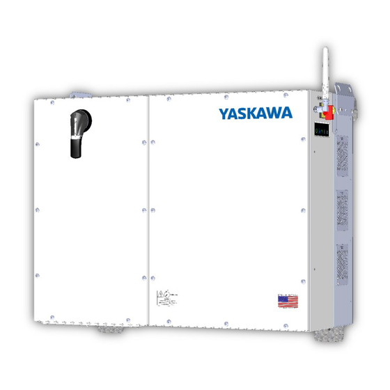
- Page 9 Installation and Operation Guide SOLECTRIA XGI 1500 (Rev A, April 2019) 2.1.4 Inverter Features Figure 2-3 SOLECTRIA XGI 1500 Inverter Features: Front (Left), Right Side (Right), and Bottom (Bottom) 9 of 77...
-
Page 10: Inverter Placement
Installation and Operation Guide SOLECTRIA XGI 1500 (Rev A, April 2019) Inverter Placement The SOLECTRIA XGI 1500 inverter is rated for outdoor use and will operate when exposed to direct sunlight or rain. To obtain the best performance and insure longevity of the inverter, it is recommended to mount the inverter out of the direct sunlight. -
Page 11: Unpacking
Installation and Operation Guide SOLECTRIA XGI 1500 (Rev A, April 2019) Unpacking When storing the packaged inverters, keep them in an area where they will not get damaged or flooded. Storage temperatures should be maintained in the range -40°F to +167°F (-40°C to +75°C). Open the box carefully to avoid damaging the contents. -
Page 12: Inverter Size, Spacing And Mounting
Installation and Operation Guide SOLECTRIA XGI 1500 (Rev A, April 2019) Inverter Size, Spacing and Mounting The dimensions of the XGI 1500 inverter are shown in Figure 3-1. 41.3 in 1048 mm 34.9 in 34.9 in 886 mm 886 mm Figure 3-1 Inverter Dimensions Mount the inverter to 1 inch strut channel as shown in Figure 3-4. - Page 13 Installation and Operation Guide SOLECTRIA XGI 1500 (Rev A, April 2019) Use Figure 3-3 to space strut channels for mounting. The holes on the bottom use the center as the reference point and the hook at the top uses the top of the upper strut channel as its reference point. Use two 8 mm ( in) bolts (not provided) to connect the bottom brackets to the strut channel.
- Page 14 Installation and Operation Guide SOLECTRIA XGI 1500 (Rev A, April 2019) When positioned on the strut, the inverter and strut channels should appear as in Figure 3-5. To secure the inverter in place, use two 8mm ( in) bolts (not provided) through the holes provided in the top face of the upper brackets, and two more through the front face of the lower bracket.
-
Page 15: Wiring
Installation and Operation Guide SOLECTRIA XGI 1500 (Rev A, April 2019) Wiring Turn the AC Switch to OFF before wiring. The AC switch is located on the right side of the inverter (Figure 2-3.) Turn AC Switch to OFF Verify the absence of AC voltage. Use conductors with a temperature rating of at minimum 90°C. - Page 16 Installation and Operation Guide SOLECTRIA XGI 1500 (Rev A, April 2019) 3.3.2 Remove Plastic Shield The Plastic Shield is a safety feature to protect the user from hazardous voltage when the inverter is energized. The shield must be removed prior to securing the AC and DC conductors in the Wiring Box. Remove the shield, shown in transparent salmon color in Figure 3-7, using a #2 Phillips-head screwdriver.
- Page 17 Installation and Operation Guide SOLECTRIA XGI 1500 (Rev A, April 2019) 3.3.3 Removable Conduit Panel All conduit connections must be made in a manner consistent with maintaining the NEMA rating of the enclosure; failure to do so could result in a loss of warranty coverage. All conduit entries must pass through the removable conduit panel.
- Page 18 Installation and Operation Guide SOLECTRIA XGI 1500 (Rev A, April 2019) Figure 3-10 DC Conduit Hole Location for Inverters Paired with Attachable Combiners Figure 3-11 Conduit Hole Location for Attachable Combiners 18 of 77...
-
Page 19: Transformer Configuration
The inverter cannot operate connected to a delta service, corner grounded service, or wye with fully insulated Neutral. For more information, please refer to Solectria’s application note on this topic: Interconnection Guidelines for Yaskawa Solectria Solar Transformerless Inverters. WYE with Floating Ground... -
Page 20: Equipment Grounding
Installation and Operation Guide SOLECTRIA XGI 1500 (Rev A, April 2019) Equipment Grounding The XGI 1500 must be bonded using equipment grounding provisions. Do not attempt to ground either DC pole. The XGI 1500 includes provisions for terminating equipment grounding conductors and other conductors used for bonding. -
Page 21: Ac Connections
Installation and Operation Guide SOLECTRIA XGI 1500 (Rev A, April 2019) AC Connections The AC connections consist of the 3 AC Phases (L1, L2, and L3), Neutral and Ground. AC wires must be rated for at least 600 VAC. Use wires within the ranges shown in Table 3-2, and sized as required to comply with local and National electrical codes. -
Page 22: Ac Breaker Specifications
AC Breaker Specifications The AC output of the Solectria XGI 1500 series inverters requires connection to a 3-pole AC breaker with ratings as specified in Table 3-3. Table 3-4 AC Breaker Specifications... -
Page 23: Dc Connections
Installation and Operation Guide SOLECTRIA XGI 1500 (Rev A, April 2019) DC Connections The PV source circuits must be combined external to the inverter using equipment such as the XGI Remote Combiner box or the XGI Attachable Combiner box. 3.8.1 General DC Connection Information The SOLECTRIA XGI 1500 is a single DC input into one MPPT zone. -
Page 24: Dc Connection Using The Xgi Remote Or Attachable Combiner
Installation and Operation Guide SOLECTRIA XGI 1500 (Rev A, April 2019) 3.8.3 Fuses Configuration and Sizes Refer to Table 3-6 for information regarding fuse sizes and configuration. Table 3-6 Attachable Combiner Box Number of DC Inputs 16, 20, 24, 26, 28 15 A, 20 A (16, 20, 24, 26 or 28 positions) Fuse Rating Options 25 A (20 positions), 30 A (16 positions) - Page 25 Installation and Operation Guide SOLECTRIA XGI 1500 (Rev A, April 2019) Table 3-7 DC Input Wire Size XGI 1500-125/125 XGI 1500-125/150 XGI 1500-150/166 XGI 1500-166/166 Minimum Wire Size 2/0 AWG 2/0 AWG 3/0 AWG 4/0 AWG (Copper) (67.4 mm (67.4 mm (85.0 mm (107 mm Maximum Wire Size...
-
Page 26: Dc Connection Using The Xgi Attachable Combiner Box
Installation and Operation Guide SOLECTRIA XGI 1500 (Rev A, April 2019) 3.10 DC Connection Using the XGI Attachable Combiner Box Figure 3-18 XGI 1500V with Attachable Combiner Box Option Electric Shock Hazard Components with hazardous voltage and energy pose the risk of electrocuting operators. Verify the absence of DC voltage and current. - Page 27 Installation and Operation Guide SOLECTRIA XGI 1500 (Rev A, April 2019) Crimp lugs for terminations on posts in Combiner and XGI wiring compartment. (2) 4/0 AWG, RHW-2 2000V 90°C Cu GND #4 AWG, RHW-2 2000V 90°C Cu Red = positive, black = negative 1.5 inch LFNC with 90-degree elbows and threaded couplings Figure 3-19 PV Output Circuit Wiring Harness Assembly...
-
Page 28: Antenna Mounting
Installation and Operation Guide SOLECTRIA XGI 1500 (Rev A, April 2019) 3.11 Antenna Mounting Mount the antenna as shown in Figure 3-22. The antenna works best when oriented vertically. Figure 3-20 Mounting the Antenna 3.12 Replace Wiring Box Cover Replace Plastic Shield Put the plastic shield back in place. -
Page 29: Startup And Verification Test
Installation and Operation Guide SOLECTRIA XGI 1500 (Rev A, April 2019) Startup and Verification Test Electrical Shock Hazard Installer may come into contact with components that have hazardous voltage and energy. Use proper safety equipment when energizing the inverter. Startup Checklist Mechanical Installation ... -
Page 30: Commissioning Test
Installation and Operation Guide SOLECTRIA XGI 1500 (Rev A, April 2019) Verify that the Status Panel illuminates READY and that neither MAINTENANCE nor POWER FAULT LED is illuminated. If the LEDs are not in this state, see Section 7 Maintenance and Troubleshooting. ... -
Page 31: Communications And User Interface
Installation and Operation Guide SOLECTRIA XGI 1500 (Rev A, April 2019) Communications and User Interface Communications Network Connection to the Internet is strongly encouraged for the SOLECTRIA XGI inverter. The gateway or cellular modem should have a direct Ethernet connection to one inverter in order to benefit from the remote capabilities inherent to the inverter, including firmware updates. - Page 32 Installation and Operation Guide SOLECTRIA XGI 1500 (Rev A, April 2019) XGI #1 XGI #2 XGI #50 Figure 5-2 SOLECTRIA XGI Inverters Connected with Ethernet Daisy Chain Figure 5-3 SOLECTRIA XGI Inverters Connected in Tree Configuration with Ethernet Switches 32 of 77...
-
Page 33: Third-Party Data Acquisition System (Das) Connection
Third-Party Data Acquisition System (DAS) Connection Ethernet Only Connection The SOLECTRIA XGI 1500 series inverter only supports Ethernet connections to a third- party DAS. The inverter can be connected to either SolrenView or to a third-party Data Acquisition System (DAS). Only Modbus TCP Ethernet connections are supported for a third-party DAS. - Page 34 Installation and Operation Guide SOLECTRIA XGI 1500 (Rev A, April 2019) The User Interface provides the operator a “hands off” means to observe and mod the inverter settings and access the inverter. Figure 5-5 Inverter with Smart Device Connected via Wi-Fi To access the inverter using Ethernet, connect an Ethernet cable from the laptop to the inverter.
-
Page 35: Inverter List
Installation and Operation Guide SOLECTRIA XGI 1500 (Rev A, April 2019) Inverter List The Inverter List shows a register of all the inverters linked to the same Wi-Fi network to which the laptop or smart device is connected. These inverters are said to comprise a cluster. Each XGI cluster consists of a maximum of 50 or 100 inverters depending upon connection type (see Section 5.2.). - Page 36 Installation and Operation Guide SOLECTRIA XGI 1500 (Rev A, April 2019) 5.5.1 Inverter Home Page Each inverter has a Home Page (see Figure 5-8) that displays an overview of the inverter’s identity and status. The Home Page displays the inverter name (Inverter 1), inverter serial number (1W17X2458720001), current time (14:34), current AC power (51.54 kW), today’s energy production (352.66 kWh) and total lifetime energy production (8.33 MWh).
- Page 37 Installation and Operation Guide SOLECTRIA XGI 1500 (Rev A, April 2019) Selecting an inverter status icon will open a display of the inverter’s current state, as shown in Figure 5-9. Menu Login/Log Out Figure 5-9 Current Status with Network and Communication Working and Maintenance with an Event The menu button is located in the upper left corner, represented by three horizontal lines ( ).
- Page 38 Installation and Operation Guide SOLECTRIA XGI 1500 (Rev A, April 2019) Figure 5-10 shows the Drop-Down Menu in Observer mode. Figure 5-10 Inverter Status Page with Drop-Down Menu (Observer Mode) 5.5.2 Inverter Menu Figure 5-11 shows the top two levels of the inverter menu that are accessible in Observer mode. To access the sub-menu items like “Inverter Info”, select “Inverter Status”...
-
Page 39: Menu Screens
Installation and Operation Guide SOLECTRIA XGI 1500 (Rev A, April 2019) Menu Screens 5.6.1 Live Measurements This screen allows a user in either Observer or Administrator mode to view the following variables. Table 5-4 Live Measurement Menu Structure Section Subsection Measurement Today’s Energy Lifetime Energy... - Page 40 Installation and Operation Guide SOLECTRIA XGI 1500 (Rev A, April 2019) Examples of “Live Measurements” screenshots are shown in Figure 5-12. Figure 5-12 Example “Live Measurements” 5.6.2 Inverter Status Figure 5-13 Inverter Status Sub-Menu 40 of 77...
-
Page 41: Inverter Configurations
Installation and Operation Guide SOLECTRIA XGI 1500 (Rev A, April 2019) 5.6.3 Inverter Info This screen allows a user in Observer or Administrator mode to view critical inverter details. Figure 5-14 Inverter Info Page (images left-to-right as scrolling down the screen) Inverter Configurations Note that for any configuration, if the user attempts to enter a value that is not supported, the user interface will reject the value and show an error message to the right of the value. - Page 42 Installation and Operation Guide SOLECTRIA XGI 1500 (Rev A, April 2019) 5.7.2 Voltage and Frequency Trip Settings Reference your interconnection agreement or consult with your utility before making changes to the voltage and frequency settings. Figure 5-16 Voltage and Frequency Trip Settings Sub-Sub-Menu 5.7.3 Abnormal AC Voltage Detection This feature allows a user in Administrator mode to set the ride through points for abnormal high and low AC...
- Page 43 Installation and Operation Guide SOLECTRIA XGI 1500 (Rev A, April 2019) 5.7.4 Abnormal Frequency Detection This feature allows a user in Administrator mode to set the trip points for abnormal high and low frequency. Figure 5-18 Abnormal AC Frequency Detection 43 of 77...
- Page 44 Installation and Operation Guide SOLECTRIA XGI 1500 (Rev A, April 2019) 5.7.5 Recovery Time This feature allows a user in Administrator mode to set the delay before re-starting after restoration of normal conditions following an abnormal frequency or voltage event that causes the inverter to trip. The default delay time is 300s (5 minutes).
- Page 45 Installation and Operation Guide SOLECTRIA XGI 1500 (Rev A, April 2019) 5.7.6 Power Limiting This feature allows a user in Administrator mode to curtail real power as a percent of nameplate real power output. Figure 5-20 Power Limiting 45 of 77...
-
Page 46: Inverter Settings
Installation and Operation Guide SOLECTRIA XGI 1500 (Rev A, April 2019) 5.7.7 Power Factor This feature allows a user in Administrator mode to control reactive power by setting a fixed power factor between 0.85 and -0.85. The default setting is 1.00. Figure 5-21 Power Factor Inverter Settings Figure 5-22 Inverter Settings Sub-Menu... - Page 47 Installation and Operation Guide SOLECTRIA XGI 1500 (Rev A, April 2019) 5.8.1 Edit Inverter Name This screen allows a user in Administrator mode to rename an inverter. Figure 5-23 Edit Inverter Name 5.8.2 Time and Date Configuration This screen allows a user in Administrator mode to set the time and date. Figure 5-24 Time and Date Configuration 47 of 77...
- Page 48 Installation and Operation Guide SOLECTRIA XGI 1500 (Rev A, April 2019) 5.8.3 Factory Default This screen allows a user in Administrator mode to reset all inverter settings to their factory default values. Once a reset is performed, the previous settings cannot be restored. Figure 5-25 Factory Default 5.8.4 Edit Lifetime Energy...
- Page 49 Installation and Operation Guide SOLECTRIA XGI 1500 (Rev A, April 2019) 5.8.5 Restart Inverter This screen allows a user in Administrator mode to restart the inverter. Figure 5-27 Restart Inverter 5.8.6 Network Status Figure 5-28 Network Status Sub-Menu 49 of 77...
- Page 50 Installation and Operation Guide SOLECTRIA XGI 1500 (Rev A, April 2019) 5.8.7 Internet Connection Status This screen allows a user in Administrator mode to see the status of the connections to the Internet, SolrenView data server, and the firmware update server. Figure 5-29 Internet Connection Status 5.8.8 Network Configuration...
- Page 51 Installation and Operation Guide SOLECTRIA XGI 1500 (Rev A, April 2019) 5.8.9 Advanced Network Configuration Figure 5-31 Advanced Network Configuration Sub-Sub-Menu 51 of 77...
-
Page 52: Wi-Fi Configuration
Installation and Operation Guide SOLECTRIA XGI 1500 (Rev A, April 2019) Wi-Fi Configuration This screen allows a user in administrator mode to define the SSID for a cluster of inverters. The Wi-Fi Network can be disabled by de-selecting this checkbox. The SSID has 3 components: Site ID, Cluster ID, and channel. -
Page 53: User Access Management
Installation and Operation Guide SOLECTRIA XGI 1500 (Rev A, April 2019) 5.9.1 Ethernet Configuration This screen allows a user in Administrator mode to enable or disable Ethernet connectivity. Figure 5-33 Ethernet Configuration 5.10 User Access Management This screen allows a user in Administrator mode to change the default password for Administrator access. 53 of 77... -
Page 54: Solrenview Monitoring Configuration
Installation and Operation Guide SOLECTRIA XGI 1500 (Rev A, April 2019) Figure 5-34 User Access Management 5.11 SolrenView Monitoring Configuration This screen allows a user in Administrator mode to enable SolrenView Monitoring. Note that SolrenView Monitoring requires a subscription and an additional fee applies. Figure 5-35 SolrenView Monitoring Configuration 54 of 77... -
Page 55: Event And Fault Logs
Installation and Operation Guide SOLECTRIA XGI 1500 (Rev A, April 2019) 5.12 Event and Fault Logs This screen allows a user in Administrator mode to view the event and fault logs. Figure 5-36 Events and Fault Logs 5.13 Edit Inverter List This screen allows a user in Administrator mode to add or remove inverters from the network. -
Page 56: System Test
Installation and Operation Guide SOLECTRIA XGI 1500 (Rev A, April 2019) 5.14 System Test This screen allows a user in Administrator mode to run the Arc Fault Self-Test. Hit Reset after conducting the test. Figure 5-38 System Test 56 of 77... -
Page 57: Firmware Update
This screen allows a user in Administrator mode to update the firmware. The SOLECTRIA XGI 1500 series inverter supports both local and remote firmware updates. Remote updates will be performed automatically from the Yaskawa Solectria Solar server or by request through our technical support department by calling (978-683-9700 ext 2). -
Page 58: First Time Startup Wizard
Installation and Operation Guide SOLECTRIA XGI 1500 (Rev A, April 2019) 5.16 First Time Startup Wizard When the inverter is started up for the first time, the user will be prompted to run the first-time Startup Wizard. The wizard comprises several screens to facilitate setting up the network of inverters. The wizard can also be accessed from the menu at any time. -
Page 59: Operation
Installation and Operation Guide SOLECTRIA XGI 1500 (Rev A, April 2019) Operation Inverter Start-Up Automatic Start-Up: The inverter will start up automatically when the output voltage and power from the PV array meet the required values and the AC grid voltage and frequency are in the normal range. Manual Start-Up: In the User interface, on the inverter home page, click the “Connect to Grid”... -
Page 60: Maintenance And Troubleshooting
Installation and Operation Guide SOLECTRIA XGI 1500 (Rev A, April 2019) Maintenance and Troubleshooting If an inverter is not running correctly, the Status Panel will show that there is an issue. When the inverter is working normally, the three leftmost LEDs are lit (Ready, Network and Communications, and Power) and the two on the right will be off (Maintenance and Power Fault). - Page 61 Installation and Operation Guide SOLECTRIA XGI 1500 (Rev A, April 2019) Check to ensure external fans are clear of debris and are operating. Critical Over Internal hardware temperature -If external fans are not operating. Temperature has exceeded the allowable limits. Contact Technical Support, fans may need to be replaced.
- Page 62 Installation and Operation Guide SOLECTRIA XGI 1500 (Rev A, April 2019) 7.1.2 Warning Events Warning events will always result in the inverter ceasing AC power production, but the inverter can self-recover if conditions causing the event cease. A warning event is indicated by the inverter illuminating the Maintenance LED (wrench).
- Page 63 Installation and Operation Guide SOLECTRIA XGI 1500 (Rev A, April 2019) Using a CAT III multi-meter verify the AC frequency. If there is a discrepancy AC Very High of greater than 2% between the AC high frequency region 2 Frequency 2 measured results and the frequency detected.
- Page 64 Installation and Operation Guide SOLECTRIA XGI 1500 (Rev A, April 2019) Power cycle the inverter. If the inverter Communication Communication processor doesn’t clear the error, contact 3 Fault hardware fault. Technical Support. Check to make sure the Ethernet connections are firmly seated. Check Network Fault A network connection has failed.
-
Page 65: Regular Preventative Maintenance
Installation and Operation Guide SOLECTRIA XGI 1500 (Rev A, April 2019) Regular Preventative Maintenance Solectria’s warranty terms require regular preventative maintenance. It is recommended to perform this service annually, adjusting the service interval as needed depending on site conditions. It may be necessary to perform the preventative maintenance more frequently during the first year to determine the appropriate service interval. - Page 66 Installation and Operation Guide SOLECTRIA XGI 1500 (Rev A, April 2019) Figure 7-1 Inverter Wiring Box 5. While the cover is off, perform a visual inspection of the wiring box compartment, looking for water, excessive debris, discoloration of components, quality of workmanship, pests, or anything else that may interfere with proper inverter operation.
- Page 67 Installation and Operation Guide SOLECTRIA XGI 1500 (Rev A, April 2019) Figure 7-2 Inverter Fan Gaurds Debris may also collect in the cooling plenum, on the heatsinks, and inductors located in this section of the inverter. A removable panel located at the rear of the inverter provides access for cleaning. Figure 7-3 Rear Access Panel 67 of 77...
- Page 68 Installation and Operation Guide SOLECTRIA XGI 1500 (Rev A, April 2019) Do not use any metallic tools within the cooling plenum as this could damage the insulation on the inductors. To clean the cooling plenum: 1. Turn off the inverter, first by moving the DC Switch on the inverter to the “OFF” position, then by turning the AC Switch on the inverter to the “OFF”...
-
Page 69: Specifications
Installation and Operation Guide SOLECTRIA XGI 1500 (Rev A, April 2019) Specifications General Specifications Table 8-1 General Specifications XGI 1500-125/125 XGI 1500-125/150 XGI 1500-150/166 XGI 1500-166/166 Max Input Voltage 1500 VDC Full Power Input 860 to 1250 VDC 860 to 1250 VDC 860 to 1250 VDC 860 to 1250 VDC Voltage Range... -
Page 70: Voltage And Frequency Limits And Trip Times
Installation and Operation Guide SOLECTRIA XGI 1500 (Rev A, April 2019) Voltage and Frequency Limits and Trip Times All models of the SOLECTRIA XGI 1500 comply with IEEE1547-2003 requirements. The tables below show its standard settings. Table 8-3 Default Voltage Limits and Trip Times Clearing Time Adjustable Up to Voltage Range (±... -
Page 71: Temperature And Altitude
Installation and Operation Guide SOLECTRIA XGI 1500 (Rev A, April 2019) Figure 8-2 Derating with DC Voltage Temperature and Altitude Table 8-5 Normal Temperature Ranges Ambient Temperature Range -40°F to +140°F (-40°C to +60°C) Derating Temperature 113°F (45°C) Storage Temperature Range -40°F to +167°F (-40°C to +75°C) Figure 8-3 Derating with Temperature 71 of 77... - Page 72 Installation and Operation Guide SOLECTRIA XGI 1500 (Rev A, April 2019) % of Rated Full Power vs Altitude Altitude (km) Figure 8-4 Derating with Altitude 72 of 77...
-
Page 73: Options
Installation and Operation Guide SOLECTRIA XGI 1500 (Rev A, April 2019) Options Yaskawa Solectria Solar offers two 1500V combiner product lines, designed exclusively to pair with SOLECTRIA XGI 1500 inverters. The Attachable Combiners (CA-XGI1500 series) are designed to mate directly to the XGI 1500 inverter and are for use in distributed PV system designs where XGI 1500 inverters with Attachable Combiners are located at positions throughout a PV array field. - Page 74 Installation and Operation Guide SOLECTRIA XGI 1500 (Rev A, April 2019) Figure 9-2 SOLECTRIA XGI 1500 with the Attachable Combiner Box UPPER MOUNTING BRACKET FUSE HOLDERS 29.5 in. BUSBARS, + AND - (750mm) GROUND TERMINAL LOWER MOUNTING BRACKET 10.6 in. 15 in.
-
Page 75: Remote Combiner (Optional)
Installation and Operation Guide SOLECTRIA XGI 1500 (Rev A, April 2019) Remote Combiner (Optional) Yaskawa Solectria Solar also offers a Remote Combiner (CR-XGI1500 series) that is exclusively compatible with the XGI 1500. The Remote Combiner is intended to be installed in the vicinity of the PV array and is typically used when the inverters are clustered in a “virtual central”... -
Page 76: Appendix
Installation and Operation Guide SOLECTRIA XGI 1500 (Rev A, April 2019) Appendix 10.1 Warranty and RMA Instructions For all warranty information, please visit: http://solectria.com/support/documentation/warranty-information/grid-tied-inverter-warranty-letter/ 10.2 Yaskawa Solectria Solar Contact Information Table 10-1 Yaskawa Solectria Solar Contact Information Telephone 978.683.9700 978.683.9702 Sales Support inverters@solectria.com Customer Support 978.683.9700 x2... -
Page 77: 10.3 Authorization To Mark
Installation and Operation Guide SOLECTRIA XGI 1500 (Rev A, April 2019) 10.3 Authorization to Mark 77 of 77...
Need help?
Do you have a question about the SOLECTRIA XGI 1500 Series and is the answer not in the manual?
Questions and answers