YASKAWA L1000A Series Technical Manual
Hide thumbs
Also See for L1000A Series:
- Technical manual (522 pages) ,
- Quick start manual (247 pages) ,
- Installation manual (20 pages)
Table of Contents
Advertisement
Advertisement
Table of Contents

Related Manuals for YASKAWA L1000A Series


Summary of Contents for YASKAWA L1000A Series
-
Page 2: Quick Reference
♦ Quick Reference Perform Auto-Tuning R efer to Types o f A uto-T uning on p a g e 9 5. Maintenance Check Using Drive Monitors R efer to P erform an ce L ife M onitors M aintenance M onitors on p a g e 27 5. Fault Display and Troubleshooting R efer to D rive A larm s, Faults, a n d E rrors on p a g e 236 R efer to Setu p Troubleshooting an d Possible S olu tion s on p a g e 126. - Page 3 Table of Contents PREFACE & GENERAL SAFETY............... 13 RECEIVING......................23 MECHANICAL INSTALLATION ................33 ELECTRICAL INSTALLATION................41...
- Page 4 START-UP PROGRAMMING & OPERATION ............ 73...
- Page 5 PARAMETER DETAILS..................133...
- Page 6 TROUBLESHOOTING..................233...
- Page 7 PERIODIC INSPECTION & MAINTENANCE ........... 269 PERIPHERAL DEVICES & OPTIONS .............. 291 SPECIFICATIONS....................313...
- Page 8 PARAMETER LIST..................... 321 MEMOBUS/MODBUS COMMUNICATIONS............367...
- Page 9 STANDARDS COMPLIANCE................395 QUICK REFERENCE SHEET................415 Index ..........................422 Revision History ......................433...
-
Page 10: Preface & General Safety
Preface & General Safety... - Page 11 i.1 Preface Preface ♦ Applicable Documentation ♦ Symbols /T E R M S ! ♦ Terms and Abbreviations • Trademarks...
-
Page 12: Supplemental Safety Information
i.2 General Safety General Safety ♦ Supplemental Safety Information A WARNING A DANGER A WARNING m a y also be in d ic a te d b y a b o ld k e y w o rd e m b e d d e d in the te xt fo llo w e d b y an ita licize d s a fe ty m essage. A CAUTION m a y also be in d ic a te d b y a b o ld k e y w o rd e m b e d d e d in the te xt fo llo w e d b y an ita lic ize d s a fe ty m essage. - Page 13 i.2 General Safety ♦ Safety Messages A DANGER Electrical Shock Hazard A WARNING Sudden Movement Hazard Electrical Shock Hazard...
- Page 14 i.2 General Safety A WARNING Fire Hazard...
- Page 15 i.2 General Safety NOTICE Equipment Hazard ♦ General Application Precautions ■ Motor Selection Drive Capacity Starting Torque ■ Stopping Emergency Stop Mechanical Brake...
- Page 16 i.2 General Safety Repetitive Starting/Stopping ■ Installation Enclosure Panels Installation Direction Refer to Mechanical Installation on page 35 In s ta ll the drive u p rig h t as sp e cifie d in the m anual. fo r m o re in fo rm atio n on installation.
-
Page 17: Motor Application Precautions
i.2 General Safety E le c trica l S ho ck H azard. W hen a drive is ru n n in g a P M m otor, volta ge con tinu es to be g e n e ra te d at the m o to r term inals a fte r the drive is shu t o ff w hile the m o to r coa sts to stop. -
Page 18: Drive Label Warnings
i.2 General Safety ■ Precautions for PM Motors D a m ag e to Equipm ent. Im p ro p e r se q u e n cin g o f o u tp u t m o to r circu its c o u ld re su lt in d a m ag e to the drive. D o n o t con ne ct e le c tro m a g n e tic sw itch es o r m a g n e tic con tactors to the o u tp u t m o to r circu its w ith ou t p ro p e r sequencing. -
Page 19: Receiving
Receiving... - Page 20 1.1 Section Safety Section Safety A CAUTION Crush Hazard NOTICE Equipment Hazard...
- Page 21 1.2 General Description General Description ♦ L1000A Model Overview 3-Phase 200 V Class 3-Phase 400 V Class Motor Power kW (HP) Model CIMR-LC Rated Output Current (A) Model CIMR-LC Rated Output Current (A) <1> <1> <1> <1> <1> <1> <1> <1>...
- Page 22 1.2 General Description ♦ Control Mode Selection Table 1.1 Table 1.1 Control Modes and their Features Permanent Motor Type Induction Motors Comments Magnet Motors...
-
Page 23: Model Number And Nameplate Check
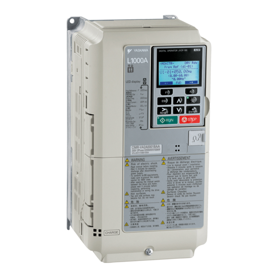
Model Number and Nameplate Check Controller Power Supply Cable for Rescue Description Drive Quick Start Guide Operation Ф Quantity ♦ Nameplate AC drive model MODEL MAX APPLI. MOTOR : 4.0kW REV : A LISTED Input specifications — INPUT AC3PH 380-480V 50/60Hz 10.4A Output specifications 7J48 B OUTPUT AC3PH 0-480V 0 -120Hz 9.2A... - Page 24 ■ Model Number and Specifications Table 1.2 Model Number and Specifications Three-Phase 200 V Three-Phase 400 V Max. Motor Capacity Rated Output Max. Motor Capacity Rated Output Current A Current A...
- Page 25 1.4 Component Names Component Names Using the D ig ita l Operator on page 77 ♦ Exploded Views of Drive Components ■ Three-Phase AC200 V CIMR-LC2A0018B to 2A0075B Three-Phase AC400 V CIMR-LC4A0009B to 4A0039B <i> <i> Exploded View of Drive Components (CIMR-LC2A0025B)
- Page 26 1.4 Component Names ■ Three-Phase AC200 V CIMR-LC2A0085B, 2A0115B, 2A0145C, and 2A0180C Three-Phase AC400 V CIMR-LC4A0045B to 4A0091B, 4A0112C, to 4A0150C...
- Page 27 1.4 Component Names ■ Three-Phase AC200 V CIMR-LC2A0215C to 2A0415C Three-Phase AC400 V CIMR-LC4A0180C to 4A0216C...
-
Page 28: Front Views
1.4 Component Names ♦ Front Views CIMR-LC2A0018B (R e fe r to W irin g th e M a in C ir c u it T e rm in a l o n p a g e 61 (R e fe r to M E M O B U S / M o d b u s T e rm in a tio n o n p a g e 69) (R e fe r to S in k in g /S o u rc in g M o d e S e le c tio n f o r S a fe D is a b le... -
Page 29: Mechanical Installation
Mechanical Installation... - Page 30 2.1 Section Safety Section Safety A WARNING Fire Hazard A CAUTION Crush Hazard NOTICE Equipment Hazard...
- Page 31 2.2 Mechanical Installation Mechanical Installation C rush H azard. C a rrying the drive b y the front c o v e r m a y cau se the m a in b o d y o f the drive to fall, re su ltin g in m in o r o r m o d e ra te injury.
- Page 32 2.2 Mechanical Installation ■ Installation Spacing Figure 2.2 ♦ Digital Operator Remote Usage ■ Remote Operation Refer to D rive Options and P eriph eral Devices on page 294...
- Page 33 2.2 Mechanical Installation ■ Digital Operator Remote Installation Digital Operator Dimensions Installation Types and Required Materials Table 2.2 Digital Operator Installation Methods and Required Tools Installation Method Description Installation Support Sets Model Required Tools P re v e n t fo reign m a tte r s uch as m e ta l s ha vin gs o r w ire c lipping s from fa llin g in to the drive d u rin g in s ta lla tio n a n d p ro je ct construction.
- Page 34 2.2 Mechanical Installation Internal/Flush-Mount Figure 2.7 Figure 2.8.
-
Page 35: Exterior And Mounting Dimensions
2.2 Mechanical Installation ♦ Exterior and Mounting Dimensions 0 ° О о о Table 2.3 Dimensions: 200 V Class Dimensions (mm) Drive Model Weight Figure CIMR-LC2A (kg) 0018 0025 0033 0047 0060 0075 0085 0115 0145 0180 0215 0283 0346 0415... - Page 36 2.2 Mechanical Installation Table 2.4 Dimensions: 400 V Class Dimensions (mm) Drive Model Weight Figure CIMR-LC4A (kg) 0009 0015 0018 0024 0031 0039 0045 0060 0075 0091 0112 0150 0180 0216...
-
Page 37: Electrical Installation
Electrical Installation... - Page 38 3.1 Section Safety Section Safety d a n g e r Electrical Shock Hazard A WARNING Sudden Movement Hazard Electrical Shock Hazard...
- Page 39 3.1 Section Safety A WARNING Sudden Movement Hazard Fire Hazard...
- Page 40 3.1 Section Safety A CAUTION Crush Hazard NOTICE Equipment Hazard...
- Page 41 3.1 Section Safety NOTICE...
- Page 42 3.2 Standard Connection Diagram Standard Connection Diagram Figure 3.1. Refer to Start-Up Programming & Operation on page 73 S udden M o ve m e n t Hazard. E nsu re h o ld in g b ra ke circu its are p ro p e rly configured, lo a d e q u ip m e n t m a y fa ll o r drop during p o w e r loss o r d rive fault, w hich c o u ld re s u lt in de ath o r seriou s injury.
- Page 43 3.2 Standard Connection Diagram Motor v m v j <10> <9>...
- Page 44 3.2 Standard Connection Diagram S udden M o v e m e n t Hazard. E nsu re start/stop a n d sa fe ty circuits are w ire d p ro p e rly a n d in the co rre ct state be fore e n e rg iz in g the drive.
- Page 45 3.3 Main Circuit Connection Diagram Main Circuit Connection Diagram Figure 3.2 D o n o t use the ne ga tive D C b u s te rm in a l “- ” as a g ro u n d term inal. This te rm in a l is a t hig h D C voltage potential. Im p ro p e r w iring con n e ctio n s c o u ld da m ag e the drive.
- Page 46 3.4 Terminal Block Configuration Terminal Block Configuration Figure 3.3 CIMR-LC2A0060, 0075 CIMR-LC2A0085, 0115 CIMR-LC4A0045, 0060 CIMR-LC2A0145, 0180, 0215, 0283, 0316, 0415 CIMR-LC4A0112, 0150, 0180, 0216 <1>...
-
Page 47: Removing The Terminal Cover
Terminal Cover ♦ Removing/Reattaching the Terminal Cover ■ Removing the Terminal Cover Models CIMR- LD2A0018 to 2A0075 and 4A0009 to 4A0039 Models CIMR-LC2A0085 to 2A0180 and 4A0045 to 4A0150 D o n o t completely^ re m o ve the c o v e r screw s, ju s t lo o s e n them . I f the c o v e r screw s are re m o v e d com pletely, the term in al c o v e r m a y fa ll o ff ca u sin g an injury. - Page 48 ■ Reattaching the Terminal Cover Models CIMR- LD2A0018 to 2A0075 and 4A0009 to 4A0039 Refer to Wiring the Main Circuit Terminal on page 61 Wiring the Control Circuit Terminal on page 64 Models CIMR-LC2A0085 to 2A0180 and 4A0045 to 4A0150 Refer to Wiring the Main Circuit Terminal on page 61 Wiring the Control Circuit Terminal on page 64...
- Page 49 Digital Operator and Front Cover ♦ Removing/Reattaching the Digital Operator ■ Removing the Digital Operator ■ Reattaching the Digital Operator ♦ Removing/Reattaching the Front Cover ■ Removing the Front Cover Models CIMR- LD2A0018 to 2A0075 and 4A0009 to 4A0039...
- Page 50 Models CIM R-LD2A0085 to 2A0415 and 4A0045 to 4A0216 Figure 3.14...
- Page 51 ■ Reattaching the Front Cover Models CIM R-LD2A0018 to 2A0075 and 4A0009 to 4A0039 Remove the Front Cover (Models CIMR-LQ2A0018 to 2A0075 and 4A0009 to 4A0039) on page 53 Models CIM R-LD2A0085 to 2A0415 and 4A0045 to 4A0216...
- Page 52 3.7 Main Circuit Wiring Main Circuit Wiring O n ly c o n n e c t re c o m m e n d e d d e vice s to the drives b ra k in g tra n s is to r term inals. F ailure to co m p ly c o u ld re s u lt in da m ag e to the drive o r b ra k in g circuit.
- Page 53 3.7 Main Circuit Wiring Closed-Loop Crimp Terminal Size on page 407 ■ Three-Phase 200 V Class Table 3.2 Wire Gauge and Torque Specifications (Three-Phase 200 V Class) Applicable Tightening Model Recommended Gauge Screw Terminal Gauge Torque CIMR-LC Size N m (lb.in.) <1>...
- Page 54 3.7 Main Circuit Wiring Applicable Tightening Model Recommended Gauge Screw Terminal Gauge Torque CIMR-LC Size N m (lb.in.) E M C F ilte r In sta lla tio n on page 398 ■ Three-Phase 400 V Class Table 3.3 Wire Gauge and Torque Specifications (Three-Phase 400 V Class) Applicable Tightening Model...
- Page 55 3.7 Main Circuit Wiring Applicable Tightening Model Recommended Gauge Screw Terminal Gauge Torque CIMR-LC Size N m (lb.in.) Ф E M C F ilte r In s ta lla tio n on page 398...
- Page 56 3.7 Main Circuit Wiring ♦ Main Circuit Terminal and Motor Wiring E le c tric a l S ho ck H azard. B efo re servicing, d isc o n n e c t a ll p o w e r to the e q u ip m e n t a n d lo c k o u t the p o w e r source. F a ilure to co m p ly m a y re s u lt in in ju ry from e le c tric a l shock.
-
Page 57: Ground Wiring
3.7 Main Circuit Wiring ■ Ground Wiring W hen using an E M C filter, the le a ka g e cu rre n t e xce ed s 3.5 mA. Therefore, a cco rd in g to IE C 61 80 0-5 -1 , a t le a s t o ne o f the co n d itio n s b e lo w m u st be satisfied: a) The cro ss-se ctio n o f the p ro te ctive ea rth in g c o n d u c to r m u s t be a t le a s t 10 m m 2 (Cu) o r 16 m m 2 (Al). - Page 58 Control Circuit Wiring ♦ Control Circuit Connection Diagram Refer to Standard Connection Diagram on page 46 ♦ Control Circuit Terminal Block Functions Figure 3.1 E q u ip m e n t H azard. Im p ro p e r e q u ip m e n t s e q u e n c in g c o u ld sho rte n u s e fu l life o f the ele ctro lytic cap acito rs a n d c ircu it relays o f the drive.
- Page 59 3.8 Control Circuit Wiring ■ Output Terminals Table 3.6 Table 3.6 Control Circuit Output Terminals Terminal Name (Function) Function (Signal Level) Default Setting Page Type ■ Serial Communication Terminals Table 3.7 Control Circuit Terminals: Serial Communications Type Signal Name Function (Signal Level) <1>...
- Page 60 3.8 Control Circuit Wiring ■ Wire Size F ire hazard. Lo ose e le c tric a l con n e ctio n s co u ld re s u lt in de ath o r s eriou s in ju ry b y fire due to o v e rh e a tin g o f e le ctrica l connections.
- Page 61 3.8 Control Circuit Wiring S eparate w iring fo r o u tp u t term in als MA, MB, MC, M1 an d M 2 from w iring to o th e r c o n tro l c ircu it lines. Im p ro p e r w iring p ra c tice s c o u ld re s u lt in drive o r e q u ip m e n t m a lfu n c tio n o r n u isa n ce trips.
- Page 62 3.8 Control Circuit Wiring Figure 3.20: Figure 3.21. Figure 3.22 D o n o t e xc e e d 50 m eters (164 ft.) fo r the c o n tro l lin e b e tw e e n the drive a n d the o p e ra to r w hen using an a n a lo g sig n a l from a re m o te sou rce to sup ply the fre q u e n cy reference.
- Page 63 3.8 Control Circuit Wiring ♦ Switches and Jumpers on the Terminal Board Figure 3.23 Control I/O Configuration on page 68...
- Page 64 3.9 Control I/O Configuration Control I/O Configuration ♦ Setting Sink/Source with Input Terminals SN and SP Table 3.10 D a m ag e to Equipm ent. D o n o t sh o rt term in als S P a n d SN. F ailure to c o m p ly w ill da m ag e the drive. Table 3.10 Digital Input Sink / Source / External Power Supply Selection Drive Internal Power Supply (Terminal SN and SP) External 24 Vdc Power Supply...
- Page 65 3.9 Control I/O Configuration ♦ MEMOBUS/Modbus Termination Table 3.12 Switches and Jumpers on the Terminal Board on page 67 Table 3.12 MEMOBUS/Modbus Switch Settings S2 Position Description M E M O B U S /M odbus Com m unications on page 367...
- Page 66 3.10 Connect to a PC 3.10 Connect to a PC...
- Page 67 3.11 Wiring Checklist 3.11 Wiring Checklist Item Page 1 57 R efer to Wire Gauges a n d Tightening Torque on p a g e 5 6 . R efer to Wire Gauges an d Tightening Torque on p a g e 5 6 R efer to Wire Gauges an d Tightening Torque on p a g e 5 6 .
- Page 68 3.11 Wiring Checklist...
- Page 69 Start-Up Programming & Operation...
- Page 70 4.1 Section Safety Section Safety d a n g e r Electrical Shock Hazard A WARNING Sudden movement Hazard Electrical Shock Hazard...
- Page 71 4.1 Section Safety A WARNING Sudden Movement Hazard Electrical Shock Hazard A CAUTION Burn Hazard...
- Page 72 4.1 Section Safety NOTICE Equipment Hazard...
- Page 73 4.2 Using the Digital Operator Using the Digital Operator ♦ Keys and Displays Display Name Function r u n □ □ <1> enter <2> k u n Щ R efer to A L A R M (ALM ) L E D D isplays on p a g e 79.
- Page 74 4.2 Using the Digital Operator ♦ LCD Display - M O D E - D R V R d y S p e e d R e (O P R ) U1-01= 0.( U1-02= 0.00% R S E Q U1-03= 0.00A L R E F F W D ■...
-
Page 75: Powering Up The Drive And Operation Status Display
4.2 Using the Digital Operator ♦ Powering Up the Drive and Operation Status Display ■ Powering Up the Drive E le c tric a l S h o c k H azard. D o n o t c o n ta ct live e le c tric a l parts. F a ilu re to co m p ly c o u ld re s u lt in de ath o r seriou s injury. N e ve r tou ch the ou tput term in als d ire c tly w ith y o u r h a n d s o r a llo w the o u tp u t lines to com e in to co n ta ct w ith the drive case. - Page 76 4.2 Using the Digital Operator ♦ LO/RE LED and RUN LED Indications Table 4.3 LO/RE LED and RUN LED Indications Flashing Flashing Quickly < > ч r Ш F ig u re 4.3 o p p o p p...
- Page 77 4.2 Using the Digital Operator ♦ Menu Structure for Digital Operator ■ E S C I Я ^Ш O i t Q Ш Щ Ш Щ o tto Н И И Н И И Ш Ж & Ж o t t a ___ t...
- Page 78 4.3 The Drive and Programming Modes The Drive and Programming Modes ♦ Navigating the Drive and Programming Modes Mode Contents Operator Display Description R efer to The D rive a n d Program m ing M odes on p a g e 82. U1-02= 0.00% RSEQ U1-03= 0.00A I lref...
- Page 79 4.3 The Drive and Programming Modes Mode Contents Operator Display Description U1-02= 0.00% RSEQ U1-03= 0.00A l r e p p w d ■ Drive Mode Details Figure 4.6 l r e p ШШ U1-02= 0.00% I U1-03= 0.00A I Ш...
- Page 80 4.3 The Drive and Programming Modes ♦ Changing Parameter Settings or Values Step Display/Result Ш Ш □...
- Page 81 4.3 The Drive and Programming Modes ♦ Verifying Parameter Changes: Verify Menu Step Display/Result 1ДАЛД fw d...
- Page 82 4.3 The Drive and Programming Modes ♦ Simplified Setup Using the Setup Group ■ Using the Setup Group Figure 4.7 p w d i d a t □ <2> p w d i s a j J a Щ^Ш <2> p w d...
-
Page 83: Switching Between Local And Remote
4.3 The Drive and Programming Modes ■ Setup Group Parameters Table 4.4 Table 4.4 Setup Group Parameters Parameter Name Parameter Name ♦ Switching Between LOCAL and REMOTE ■ Using the LO/RE Key on the Digital Operator Step Display/Result U1-02= 0.00% IRSEQI U1-03= 0.00A I s e t - ¥... - Page 84 4.4 Start-Up Flowcharts Start-Up Flowcharts Types o f Auto-Tuning on page 95 Flowchart Purpose Page...
- Page 85 4.4 Start-Up Flowcharts ♦ Flowchart A: Installation, Wiring, Basic Setup for Motor and Elevator...
- Page 86 4.4 Start-Up Flowcharts ♦ Power On S udden M o v e m e n t Hazard. E nsu re start/stop, I/O a n d s a fe ty circuits are w ire d p ro p e rly a n d in the co rre c t state before e n e rg iz in g o r ru n n in g the drive.
- Page 87 4.4 Start-Up Flowcharts E le ctrica l S h o ck Hazard. D o n o t c o n n e c t o r d is c o n n e c t w iring w hile the p o w e r is on. F ailure to c o m p ly w ill re s u lt in de ath or seriou s injury.
- Page 88 4.4 Start-Up Flowcharts ♦ Flowchart B: Auto-Tuning for Induction Motors “ Щ п E n d...
- Page 89 4.4 Start-Up Flowcharts ♦ Flowchart C: Auto-Tuning for PM Motors Auto-Tuning Fault Detection on page 260 <1> <1> <2> Flowchart D: PG Encoder Offset Auto-Tuning on page 94 □ lU n “ E n d "...
- Page 90 4.4 Start-Up Flowcharts ♦ Flowchart D: PG Encoder Offset Auto-Tuning <1> <2> <1> <1> Auto-Tuning Fault Detection on page 260 Auto-Tuning Fault Detection on page 260 E r S S ” .
- Page 91 4.5 Auto-Tuning Auto-Tuning S ud de n M o ve m e n t H azard. The drive an d m o to r m a y start u n e x p e c te d ly du rin g A uto-Tuning, w hich c o u ld re s u lt in death o r seriou s injury.
- Page 92 4.5 Auto-Tuning ■ Auto-Tuning for Permanent Magnet Motors Table 4.7 Types of Auto-Tuning for Permanent Magnet Motors Type Setting Requirements and Benefits Table 4.8 Flowchart C: Auto-Tuning fo r P M Motors on page 93 Table 4.8 Auto-Tuning Input Data Tuning Type (T2-01) Initial Input...
- Page 93 4.5 Auto-Tuning Table 4.9 Types of Auto-Tuning for PG Encoder Offset Setting Requirements and Benefits Type...
- Page 94 4.5 Auto-Tuning ♦ Before Auto-Tuning the Drive ■ Basic Auto-Tuning Preparations and Precautions S udden M o ve m e n t H azard. W hen p e rfo rm in g R o ta tio n a l A uto -T u nin g fo r m o to r data o r P G e n c o d e r offset, alw ays u n cou ple the m o to r from the m e c h a n ic a l system (rem o ve ro p e s from traction sheave).
- Page 95 4.5 Auto-Tuning Table 4.10 Table 4.10 Digital Input and Output Operation During Auto-Tuning Motor Type Auto-Tuning Type Digital Input Digital Output IM Motor PM Motor ♦ Auto-Tuning Interruption and Fault Codes gj ^ A LMi j Ш ♦ Auto-Tuning Operation Example ■...
- Page 96 4.5 Auto-Tuning Step Display/Result ■ Enter Data from the Motor Nameplate Step Display/Result П fw d П К Ж fw d Refer to Parameter Settings d u rin g In d u c tio n M o to r A uto -T u nin g: T1 on page 101...
- Page 97 4.5 Auto-Tuning ■ Starting Auto-Tuning S ud de n M o ve m e n t H azard. The drive an d m o to r m a y start u n e x p e c te d ly du rin g A uto-Tuning, w hich c o u ld re s u lt in death o r s eriou s injury.
- Page 98 4.5 Auto-Tuning ■ T1-03: Motor Rated Voltage Name Setting Range Default <1> <1> ■ T1-04: Motor Rated Current Name Setting Range Default ■ T1-05: Motor Base Frequency Name Setting Range Default ■ T1-06: Number of Motor Poles Name Setting Range Default ■...
- Page 99 4.5 Auto-Tuning ■ T1-09: Motor No-Load Current Name Setting Range Default <1> Table A.1 Table A .2 ), ■ T1-10: Motor Rated Slip Name Setting Range Default ♦ Parameter Settings during PM Motor Auto-Tuning: T2 ■ T2-01: PM Auto-Tuning Mode Selection Refer to Auto-Tuning fo r Permanent Magnet Motors on page 96 Name Setting Range...
- Page 100 4.5 Auto-Tuning ■ T2-08: Number of PM Motor Poles Name Setting Range Default ■ T2-09: PM Motor Base Speed Name Setting Range Default ■ T2-10: PM Motor Stator Resistance Name Setting Range Default ■ T2-11: PM Motor d-Axis Inductance Name Setting Range Default ■...
-
Page 101: Up And Down Commands And Speed Reference Selection
4.6 Setup Procedure for Elevator Applications Setup Procedure for Elevator Applications ♦ Up and Down Commands and Speed Reference Selection S ud de n M o v e m e n t H azard. R e m ove the U p/D ow n C o m m a n d b e fo re re se ttin g a larm s a n d faults. F ailure to co m p ly can re s u lt in de ath o r s eriou s injury. - Page 102 4.6 Setup Procedure for Elevator Applications ♦ Speed Selection Using Digital Inputs (b1-01 = 0) A lw a y s turn o ff the R U N c o m m a n d b e fore ch a n g in g the settin g o f p a ra m e te rs d1 -1 8 (S p e e d R e fe re n c e S electio n M ode), b1- 01 (S p e e d R e fe ren ce Selection), o r H 1 - \3 \3 (M ulti-F u nction D ig ita l Inputs).
- Page 103 4.6 Setup Procedure for Elevator Applications Leveling and Nominal Speed assigned Leveling speed not assigned Nominal Speed not assigned (H 1-D D = 50 and H 1-D D = 53) (H 1-D D (H 1-D D ф Selected Speed ф Higher Speed has Priority and the Leveling Speed Input is Assigned (d1-18 = 1 and H 1 -D D = 53) (Default) Higher Speed Priority is Selected and the Leveling Speed Input is Not Assigned (d1-18 = 1 and H 1-D D ф...
-
Page 104: Figure
4.6 Setup Procedure for Elevator Applications Leveling Speed Priority is Selected and the Nominal Speed Input is Not Assigned (d1-18 = 2, H 1 -D D ф E q u ip m e n t Hazard. This fu n ctio n m a y n o t w o rk p ro p e rly i f a b ro k e n w ire con ne ction to the drive I/O cau ses im p ro p e r e le v a to r s p e e d selection. -
Page 105: Figure
4.6 Setup Procedure for Elevator Applications • Inspection Operation ■ Start Condition in Inspection Operation A lw a y s turn o ff the R U N c o m m a n d b e fore ch a n g in g the settin g o f p a ra m e te rs d1 -1 8 (S p e e d R e fe ren ce S electio n M ode), b1- 01 (S p e e d R e fe ren ce Selection), o r (M u lti-F u nction D ig ita l Inputs). -
Page 106: Brake Sequence
4.6 Setup Procedure for Elevator Applications ♦ Brake Sequence S udden M o ve m e n t H azard. R a p id d e celeratio n m a y cau se the drive to fa u lt on an o ve rvolta ge condition, re su ltin g in death o r s eriou s in ju ry due to an un co n tro lle d m o to r state. - Page 107 4.6 Setup Procedure for Elevator Applications ■ Brake Sequence Using Torque Compensation Figure 4.16 „<1 Figure 4.16 Table 4.12 Table 4.12 Time Zones for Brake Sequence Using Torque Compensation at Start T im e Z o n e D e s c rip tio n...
- Page 108 4.6 Setup Procedure for Elevator Applications Adjusting the Torque Compensation at Start S et a ll m o to r-re la te d p a ra m e te rs (the p a ram e te rs) a n d p e rfo rm a te st run b e fore fin e -tu n in g the torque com p e n sa tio n a t start.
- Page 109 4.6 Setup Procedure for Elevator Applications Figure 4.15 • Adjustments for Elevator Ride Comfort Riding Comfort Related Problems on page 128 ■ Speed Loop Adjustments (CLV and CLV/PM)
- Page 110 4.6 Setup Procedure for Elevator Applications ■ Inertia Compensation (CLV and CLV/PM) п ■ Adjusting Position Lock at Start (CLV/PM) • Rescue Operation E q u ip m e n t Hazard. D o n o t use the R e scue O pe ra tion fea tu re fo r e xte n d e d periods. F ailure to co m p ly m a y re su lt in drive h e a t s in k ove rte m p e ra tu re alarm s (oH).
-
Page 111: Wiring Examples
4.6 Setup Procedure for Elevator Applications Table 4.13 Table 4.13 Power Supply Ratings for Rescue Operation Motor Type Speed Feedback DC Bus Voltage Control Circuit Voltage ■ Parameter Setup ■ Wiring Examples E le c tric a l S h o ck H azard. D o n o t con ne ct o r d isco n n e ct w iring w hile the p o w e r is on. N e v e r re m o ve o r in s ta ll op tion cards o r a tte m p t to rep la ce the c o o lin g fan w hile the drive is s w itc h e d on. - Page 112 4.6 Setup Procedure for Elevator Applications ■ Using a Single-Phase, 230 Vac UPS (Uninterruptable Power Supply) Wiring Figure 4.19 Operation Sequence Application Precautions...
- Page 113 4.6 Setup Procedure for Elevator Applications ■ Using Separate Batteries for DC Bus and Control Power Supply, DC Bus Battery under 250 Vdc (500 Vdc) Wiring Figure 4.20. Connecting the Drive and Battery on page 120 ___ s __________ Operation Sequence...
- Page 114 4.6 Setup Procedure for Elevator Applications ■ Using a Battery for the DC Bus and 24 V Power Supply Unit Option for the Control Circuit Wiring Figure 4.21. Operation Sequence...
- Page 115 4.6 Setup Procedure for Elevator Applications ■ Using a Single Battery with Minimum 250 Vdc (500 Vdc) Wiring Figure 4.22. г Operation Sequence Starting Rescue Operation Ending Rescue Operation...
- Page 116 4.6 Setup Procedure for Elevator Applications ■ Connecting the Drive and Battery Table 4.13 Sw itch o ff the p o w e r s u p p ly b e fo re w iring a n d co n n e ctin g the b a tte ry cable. F a ilure to co m p ly w ill le a d to de ath o r serious in ju ry from electric shock.
- Page 117 4.6 Setup Procedure for Elevator Applications Figure 4.26. M ake sure the cab le do es n o t g e t p in c h e d b e tw e e n the drive a n d the c o n n e c to r cover, as this co u ld d a m ag e the cable.
- Page 118 4.6 Setup Procedure for Elevator Applications Models CIM R-LD2A0085 to 2A0415, CIM R-LD4A0045 to 4A0216 Figure 4.29. 0 = 0 Figure 4.30, Figure 4.30.
- Page 119 4.6 Setup Procedure for Elevator Applications B e sure th a t the c o n n e cto r fasten s a t the corre ct an gle to the C N 19 co n n e c to r port. The in c o rre ct an gle c o u ld d a m ag e the battery, cable, o r connector.
- Page 120 4.6 Setup Procedure for Elevator Applications Use the s c re w p ro v id e d to fasten the co n n e c to r c o v e r in to place. U sing a d iffe re n t s cre w m a y da m ag e the in te rn a l drive com ponents.
- Page 121 4.6 Setup Procedure for Elevator Applications...
-
Page 122: Cannot Change Parameter Settings
4.7 Setup Troubleshooting and Possible Solutions Setup Troubleshooting and Possible Solutions Symptom Page 1 26 1 26 1 2 7 1 2 7 1 2 7 1 2 7 1 2 7 ♦ Cannot Change Parameter Settings Cause Possible Solutions The D rive an d Program m ing M odes on p a g e 82. - Page 123 4.7 Setup Troubleshooting and Possible Solutions Cause Possible Solutions ■ Motor Rotates in the Opposite Direction from the Up/Down Command Cause Possible Solutions M otor R otation D irection S etu p on p a g e 90 P G Encoder S etu p on p a g e 9 1 .
- Page 124 4.7 Setup Troubleshooting and Possible Solutions ♦ Riding Comfort Related Problems Problem Control Mode and Possible Cause Corrective Action S p eed L oop A dju stm ents (C L V a n d CLV/PM ) on p a g e 113. Inertia Com pensation (C L V a n d CL V / PM ) on p a g e 114.
- Page 125 4.7 Setup Troubleshooting and Possible Solutions Problem Control Mode and Possible Cause Corrective Action...
- Page 126 Verifying Parameter Settings and Backing Up Changes Refer to Verifying Parameter Changes: Verify Menu on page 85. ♦ Backing Up Parameter Values: o2-03 Parameter Name Description Setting Range Default Setting ♦ Parameter Access Level: A1-01 Parameter Setting Description Default Name Range ♦...
- Page 127 4.8 Verifying Parameter Settings and Backing Up Changes • Copy Function Refer to o3: Copy Function on page 215...
- Page 128 4.8 Verifying Parameter Settings and Backing Up Changes...
- Page 129 Parameter Details...
- Page 130 5.1 A: Initialization A: Initialization ♦ A1: Initialization ■ A1-00: Language Selection Parameter Name Setting Range Default Setting 0: English Setting 1: Japanese Setting 2: German Setting 3: French Setting 4: Italian Setting 5: Spanish Setting 6: Portuguese Setting 7: Chinese ■...
- Page 131 5.1 A: Initialization Setting 2: Open Loop Vector Control Setting 3: Closed Loop Vector Control Setting 7: Closed Loop Vector Control for PM Motors ■ A1-03: Initialize Parameters Parameter Name Setting Range Default Setting 0: No initialization Setting 1110: User Initialize Setting 2220: 2-Wire Initialization Setting 5550: oPE04 Reset Notes on Parameter Initialization...
- Page 132 5.1 A: Initialization ■ A1-04, A1-05: Password and Password Setting Parameter Name Setting Range Default How to use the Password Table 5.2 Setting the Password for Parameter Lock...
- Page 133 5.1 A: Initialization Step Display/Result Table 5.3 Check to see if A1-02 is locked (continuing from step 10 above) Step Display/Result f w d я Е Ш Н f w d п а т д Table 5.4 Enter the Password to Unlock Parameters (continuing from step 3 above) Step Display/Result Ч...
- Page 134 5.1 A: Initialization ♦ A2: User Parameters ■ A2-01 to A2-32: User Parameters 1 to 32 Saving User Parameters ■ A2-33: User Parameter Automatic Selection Setting 0: Do not save list of recently viewed parameters. Setting 1: Save history of recently viewed parameters.
- Page 135 5.2 b: Application b: Application ♦ b1: Operation Mode Selection ■ b1-01: Speed Reference Selection A lw a y s turn o ff the R U N c o m m a n d b e fore ch a n g in g the settin g o f p a ra m e te rs d1 -1 8 (S p e e d R e fe ren ce S electio n M ode), b1- 01 (S p e e d R e fe ren ce Selection), o r (M u lti-F u nction D ig ita l Inputs).
- Page 136 5.2 b: Application ■ b1-02: Up/Down Command Selection Parameter Name Setting Range Default Setting 0: Operator Setting 1: Control Circuit Terminal Setting 2: MEMOBUS/Modbus Communications MEMOBUS/ Modbus Configuration on page 368 Setting 3: Option Card ■ b1-03: Stopping Method Selection Parameter Name Setting Range Default...
- Page 137 5.2 b: Application ■ b1-08: Up/Down Command Selection while in Programming Mode Parameter Name Setting Range Default Setting 0: Disabled Setting 1: Enabled Setting 2: Prohibit programming during run ■ b1-14: Phase Order Selection Parameter Name Setting Range Default Setting 0: Standard phase order (U-V-W) Setting 1: Switched phase order (U-W-V) ♦...
- Page 138 5.2 b: Application ♦ b4: Delay Timers ■ b4-01, b4-02: Timer Function On-Delay, Off-Delay Time Name Setting Range Default ■ Timer Function Operation Figure 5.2 ■4 ♦ b6: Dwell Function Figure 5.3 ■ b6-01, b6-02: Dwell Speed, Dwell Time at Start Name Setting Range Default...
- Page 139 5.2 b: Application ♦ b7: Droop Control (CLV/PM) ■ b7-01: Droop Control Gain Parameter Name Setting Range Default ■ b7-02: Droop Control Delay Time Parameter Name Setting Range Default ♦ b8: Energy Saving ■ b8-01: Energy Saving Control Selection Parameter Name Setting Range Default Setting 0: Disabled...
- Page 140 5.3 C: Tuning C: Tuning ♦ C1: Acceleration and Deceleration Ramps ■ C1-01 to C1-08: Accel, Decel Ramps 1 to 4 Parameter Name Setting Range Default <1> <1> Switching Acceleration Ramps by Digital Input Table 5.6 Table 5.6 Accel/Decel Ramp Selection by Digital Input Active Ramps Accel/Decel Ramp Sel.
- Page 141 5.3 C: Tuning Switching Acceleration and Deceleration Times by Motor Selection Table 5.7 Table 5.7 Motor Switching and Accel/Decel Time Combinations Motor 1 Selected (Terminal set to И1-ПП =16 OFF) Motor 2 Selected (Terminal set to И1-ПП =16 ON) Accel/Decel Time 1 (И 1-П П = 7) Accel Decel Accel...
- Page 142 5.3 C: Tuning ■ C1-10: Accel/Decel Setting Resolution Parameter Name Setting Range Default Setting 0: Two decimal places Setting 1: One decimal place ■ C1-12/C1-13: Motor 2 Acceleration Time/Motor 2 Deceleration Time Parameter Name Setting Range Default ■ C1-15: Inspection Deceleration Ramp Inspection Operation on page 109 Parameter Name Setting Range...
- Page 143 5.3 C: Tuning • C3: Slip Compensation ■ C3-01: Slip Compensation Gain Parameter Name Setting Range Default ■ C3-02: Slip Compensation Primary Delay Time Parameter Name Setting Range Default ■ C3-03: Slip Compensation Limit Parameter Name Setting Range Default Figure 5.8. ■...
- Page 144 5.3 C: Tuning ■ C3-05: Output Voltage Limit Operation Selection Parameter Name Setting Range Default Setting 0: Disabled Setting 1: Enabled ■ C3-21: Motor 2 Slip Compensation Gain C3-01: Slip Compensation Gain on page 147 Parameter Name Setting Range Default ■...
- Page 145 5.3 C: Tuning ♦ C4: Torque Compensation ■ C4-01: Torque Compensation Gain Parameter Name Setting Range Default Torque Compensation in V/f: Torque Compensation in OLV: Adjustment ■ C4-02: Torque Compensation Primary Delay Time Parameter Name Setting Range Default Adjustment ■ C4-03: Torque Compensation at Forward Start Parameter Name Setting Range Default...
- Page 146 5.3 C: Tuning ■ C4-07: Motor 2 Torque Compensation Gain C3-01: Slip Compensation Gain on page 147 Parameter Name Setting Range Default ♦ C5: Speed Control Loop ■ Adjusting the Speed Control Loop Parameters H4: Multi-Function Analog Outputs on page 186 C5-01, C5-03, C5-13 / C5-02, C5-04, C5-14: Speed Control Loop Proportional Gain 1, 2, 3 / Speed Control Loop Integral Time 1, 2, 3 on page 151.
- Page 147 5.3 C: Tuning ■ C5-01, C5-03, C5-13 / C5-02, C5-04, C5-14: Speed Control Loop Proportional Gain 1, 2, 3 / Speed Control Loop Integral Time 1, 2, 3 Parameter Name Setting Range Default Speed Control Loop Gain Tuning (C5-01, C5-03, C5-13) Speed Control Loop Integral Time Tuning (C5-02, C5-04, C5-14) ■...
- Page 148 5.3 C: Tuning ■ C5-08: Speed Control Loop Integral Limit Parameter Name Setting Range Default ■ C5-16: Speed Control Loop Delay Time during Position Lock Parameter Name Setting Range Default ■ C5-17, C5-18: Motor Inertia, Load Inertia Ratio Parameter Name Setting Range Default ■...
- Page 149 5.3 C: Tuning ■ C6-21: Inspection Operation Carrier Frequency Parameter Name Setting Range Default Setting 0: Use the value set to C6-03 Setting 1: 2 kHz ■ C6-23: Carrier Frequency during Initial Motor Pole Search Parameter Name Setting Range Default Setting 0: 2 kHz Setting 1: Use the value set to C6-03 ■...
- Page 150 5.4 d: Reference Settings d: Reference Settings ♦ d1: Speed Reference ■ d1-01 to d1-08: Speed References 1 to 8 Parameter Name Setting Range Default <1> <1> Defaults and Setting Ranges by Display U n it Selection (o1- 03) on page 365 Multi-Speed Inputs 1, 2 (d1-18 = 0 or 3) on page 106 ■...
- Page 151 5.4 d: Reference Settings ■ d1-20, d1-21, d1-22: Intermediate Speeds 1 to 3 Name Setting Range Default <1> <1> <1> <1> <1> <1> Defaults and Setting Ranges by Display U nit Selection (o1-03) on page 365 ■ d1-23: Releveling Speed Name Setting Range Default...
- Page 152 5.4 d: Reference Settings ■ d1-27: Motor 2 Speed Reference Name Setting Range Default ■ d1-28: Leveling Speed Detection Level C5: Speed Control Loop on page 150 Name Setting Range Default ■ d1-29: Inspection Speed Detection Level Inspection Operation on page 109 Name Setting Range Default...
- Page 153 5.5 E: Motor Parameters E: Motor Parameters ♦ E1: V/f Pattern ■ E1-01: Input Voltage Setting S et p a ra m e te r E1-01 to m a tch the in p u t volta ge o f the drive. The drive in p u t voltage (not m o to r voltage) m u s t be s e t in E1-01 fo r the p ro te c tiv e fea tu res to fun ction properly.
- Page 154 5.5 E: Motor Parameters CLV/PM ♦ E2: Motor Parameters Auto-Tuning Fault Detection on page 260. ■ E2-01: Motor Rated Current Parameter Name Setting Range Default ■ E2-02: Motor Rated Slip Parameter Name Setting Range Default ■ E2-03: Motor No-Load Current Parameter Name Setting Range Default...
- Page 155 5.5 E: Motor Parameters ■ E2-04: Number of Motor Poles Parameter Name Setting Range Default ■ E2-05: Motor Line-to-Line Resistance Parameter Name Setting Range Default ■ E2-06: Motor Leakage Inductance Parameter Name Setting Range Default ■ E2-07: Motor Iron-Core Saturation Coefficient 1 Parameter Name Setting Range Default...
- Page 156 5.5 E: Motor Parameters ■ E2-11: Motor Rated Power Parameter Name Setting Range Default ■ Setting Motor Parameters Manually Setting the Motor Rated Current Setting the Motor Rated Slip Setting the No-Load Current Setting the Number of Motor Poles Setting the Line-to-Line Resistance Setting the Motor Leakage Inductance Setting the Motor Iron-Core Saturation Coefficient 1, 2 Setting the Motor Mechanical Loss...
- Page 157 5.5 E: Motor Parameters ♦ E3: V/f Pattern for Motor 2 Refer to Setting 16: Motor 2 selection on page 173 ■ E3-04 to E3-10 Figure 5.14. Refer to Param eter Table on page 324 Parameter Name Setting Range Default <1>...
- Page 158 5.5 E: Motor Parameters ■ E4-02: Motor 2 Rated Slip Refer to E2-02: Motor Rated Slip on page 158 Parameter Name Setting Range Default ■ E4-03: Motor 2 Rated No-Load Current Parameter Name Setting Range Default ■ E4-04: Motor 2 Motor Poles Parameter Name Setting Range Default...
- Page 159 5.5 E: Motor Parameters ■ E5-03: Motor Rated Current Parameter Name Setting Range Default ■ E5-04: Number of Motor Poles Parameter Name Setting Range Default ■ E5-05: Motor Stator Resistance (Single Phase) Parameter Name Setting Range Default ■ E5-06: Motor d-Axis Inductance Parameter Name Setting Range Default...
- Page 160 5.6 F: Option Settings F: Option Settings ♦ F1: Encoder/PG Feedback Settings ■ F1-01: Encoder 1 Resolution Parameter Name Setting Range Default <1> ■ F1-02, F1-14: PG Open (PGo) Circuit Operation Selection, Detection Time Parameter Name Setting Range Default Parameter F1-02 Settings: Setting 0: Ramp to stop (uses the deceleration ramp set to C1-02) Setting 1: Coast to stop Setting 2: Fast Stop (uses the Fast Stop ramp set to C1-09)
- Page 161 5.6 F: Option Settings ■ F1-04, F1-10, F1-11: Operation at Speed Deviation (dEv), Detection Level, Delay Time Parameter Name Setting Range Default Settings fo r Parameter F1-04: Setting 0: Ramp to stop (uses the deceleration ramp set to C1-02) Setting 1: Coast to stop Setting 2: Fast Stop (uses the Fast Stop ramp set to C1-09) Setting 3: Alarm only (drive continues operating while “dEv”...
- Page 162 5.6 F: Option Settings ■ F1-20: PG Option Card Disconnect Detection 1 Parameter Name Setting Range Default Setting 0: Disabled Setting 1: Enabled ■ F1-29: dEv Detection Condition Selection Parameter Name Setting Range Default Setting 0: After speed reference, SFS output and motor speed have matched once. Setting 1: After speed reference, SFS output have matched once.
- Page 163 5.6 F: Option Settings ■ F1-52: Communication Speed of Serial Encoder Selection Parameter Name Setting Range Default 0: 1M bps / 9600 bps (EnDat 2.2/22 / Hiperface) 1: 500k bps / 19200 bps (EnDat 2.2/22 / Hiperface) 2: 1M bps / 38400 bps (EnDat 2.2/22 / Hiperface) 3: 1M bps / 38400 bps (EnDat 2.2/22 / Hiperface) ■...
- Page 164 5.6 F: Option Settings ■ F3-03: DI-A3 Option Card Data Length Selection Parameter Name Setting Range Default Setting 0: 8 bit Setting 1: 12 bit Setting 2: 16 bit ♦ F4: Analog Monitor Card Settings ■ F4-01, F4-03: Terminal V1, V2 Function Selection Parameter Name Setting Range Default...
- Page 165 5.6 F: Option Settings ■ F4-07, F4-08: Terminal V1, V2 Signal Level Selection Parameter Name Setting Range Default Setting 0: 0 to 10 V Setting 1: -10 to 10 V ♦ F5: Digital Output Card Settings ■ F5-01 through F5-08: Digital Output Option Card Terminal Function Selection Name Setting Range Default...
- Page 166 5.6 F: Option Settings ■ F6-02: External Fault from Communication Option Detection Selection Parameter Name Setting Range Default Setting 0: Always detected Setting 1: Detection during run only ■ F6-03: External Fault from Communication Option Operation Selection Parameter Name Setting Range Default Setting 0: Ramp to stop (uses the deceleration ramp set to C1-02) Setting 1: Coast to stop...
- Page 167 5.7 H: Terminal Functions H: Terminal Functions ♦ H1: Multi-Function Digital Inputs A lw a y s turn o ff the R U N c o m m a n d b e fore ch a n g in g the settin g o f p a ra m e te rs d1 -1 8 (S p e e d R e fe ren ce S electio n M ode), b1- 01 (S p e e d R e fe ren ce Selection), o r (M u lti-F u nction D ig ita l Inputs).
- Page 168 5.7 H: Terminal Functions Setting 8, 9: Baseblock command Drive Operation Digital Input Function Input Open Input Closed S udden M o ve m e n t Hazard. W hen u s in g a m e c h a n ic a l h o ld in g b ra ke w ith the drive in a liftin g application, close the brake w hen the drive o u tp u t is cu t o ff b y a b a s e b lo c k c o m m a n d trig g e re d b y one o f the in p u t term inals.
- Page 169 5.7 H: Terminal Functions Setting 16: Motor 2 selection Figure 5.17. -tth -tth -fH - Table 5.11 Table 5.11 Parameters for Switching Between Two Motors Setting 16 Open (Motor 1) Setting 16 Closed (Motor 2) M otor Switch Selection on page 155 Setting 18: Tim er function input b4: Delay Timers on page 142 Setting 1A: Accel/decel ramp selection 2...
- Page 170 5.7 H: Terminal Functions Terminal Status Detection Conditions Stopping Method < > < > Setting Detected during Ramp to Stop Coast to Stop Emergency Stop Alarm Only N.O. N.C. Always Detected Run only (fault) (fault) (fault) (continue running) Setting 50: Nominal speed Multi-Speed Inputs 1, 2 (d1-18 = 0 or 3) on page 106 Setting 51: Intermediate speed...
- Page 171 5.7 H: Terminal Functions Setting 5C: Stop Distance Correction Refer to Stop Distance on page 353 Setting 67: Communication test mode Self-Diagnostics on page 393 Setting 79: Brake feedback ♦ H2: Multi-Function Digital Outputs ■ H2-01 to H2-05: Terminals M1-M2, M3-M4, M5-M6, P1-PC, and P1-P2 Function Selection Table 5.12 Parameter Name Setting Range...
- Page 172 5.7 H: Terminal Functions Setting 1: Zero Speed Status Description Setting 2: Speed agree 1 (fref/fout Agree 1) Status Description L4-01, L4-02: Speed Agreement Detection Level and Detection Width on page 193 Setting 3: User-set speed agree 1 (fref/fset Agree 1) Status Description L4-01, L4-02: Speed Agreement Detection Level and Detection Width on page 193...
- Page 173 5.7 H: Terminal Functions Setting 4: Speed Detection 1 Status Description L4-01, L4-02: Speed Agreement Detection Level and Detection Width on page 193 Setting 5: Speed Detection 2 Status Description L4-01, L4-02: Speed Agreement Detection Level and Detection Width on page 193...
- Page 174 5.7 H: Terminal Functions Setting 6: Drive ready Setting 7: DC bus undervoltage Status Description Setting 8: During baseblock (N.O.) Status Description Setting 9: Speed reference source Status Description Setting A: Up/Down command source Status Description Setting B, 18: Torque detection 1, Torque detection 2 L6: Torque Detection on page 196 Setting...
- Page 175 5.7 H: Terminal Functions Setting F: Not used (Through mode) Setting 10: Minor fault Setting 11: Fault reset command active Setting 12: Tim er output b4: Delay Timers on page 142 Setting 13: Speed agree 2 (fref /fout agree 2) Status Description L4-03, L4-04: Speed Agreement Detection Level and Detection Width (+/-) on page 193...
- Page 176 5.7 H: Terminal Functions Setting 15: Speed detection 3 Status Description L4-03, L4-04: Speed Agreement Detection Level and Detection Width (+/-) on page 193 Setting 16: Speed detection 4 Status Description L4-03, L4-04: Speed Agreement Detection Level and Detection Width (+/-) on page 193...
- Page 177 5.7 H: Terminal Functions Setting 1A: During down direction Status Description Setting 1B: During baseblock (N.C.) Status Description Setting 1C: Motor 2 selection Setting 16: Motor 2 selection on page 173 Status Description Setting 1D: During regeneration Setting 1E: Reset enabled L5: Automatic Fault Reset on page 194 Setting 1F: Motor overload alarm (oL1)
- Page 178 5.7 H: Terminal Functions Setting 30: During torque limit L7-01 to L7-04: Torque Limits on page 198 Setting 33: Within position lock bandwidth Setting 37: During frequency output Status Description Setting 47: Input phase loss Setting 4E: Braking transistor fault (rr) Setting 50: Brake control Brake Sequence on page 110 Setting 51: Output contactor control...
- Page 179 5.7 H: Terminal Functions Setting 58: Safe disable status Setting 60: Internal cooling fan alarm Setting 61: Motor pole search status Refer to Initial Rotor Pole Position Search Settings on page 208 < > ---------------------------- Setting 100 to 161: Functions 0 to 61 with Inverse Output ♦...
- Page 180 5.7 H: Terminal Functions ■ H3-03, H3-04: Terminal A1 Gain and Bias Settings Name Setting Range Default Setting Examples ■ H3-09: Terminal A2 Signal Level Selection Name Setting Range Default Setting 0: 0 to 10 Vdc Setting 0: 0 to 10 Vdc on page 183 Setting 1: -1 0 to 10 Vdc Setting 1: -1 0 to 10 Vdc on page 183...
- Page 181 5.7 H: Terminal Functions ■ H3-10: Terminal A2 Function Selection Multi-Function Analog Input Terminal Settings on page 185 Name Setting Range Default ■ H3-11, H3-12: Terminal A2 Gain and Bias Setting Name Setting Range Default ■ H3-13: Analog Input Filter Time Constant Name Setting Range Default...
- Page 182 5.7 H: Terminal Functions Setting 0: Speed reference bias Setting 2: Auxiliary speed reference 1 (used as a second speed reference) Speed Selection Using Digital Inputs (b1-01 = 0) on page 106 Setting 3: Auxiliary speed reference 2 (used as a third speed reference) Speed Selection Using Digital Inputs (b1-01 = 0) on page 106 Setting 14: Torque compensation (load cell input)
- Page 183 5.7 H: Terminal Functions Using Gain and Bias to Adjust Output Signal Level...
- Page 184 5.7 H: Terminal Functions ■ H4-07, H4-08: Terminal FM, AM Signal Level Selection Name Setting Range Default Setting 0: 0 to 10 V Setting 1: -10 V to 10 V ♦ H5: MEMOBUS/Modbus Serial Communication MEMOBUS/ Modbus Communications on page 367...
- Page 185 5.8 L: Protection Functions L: Protection Functions ♦ L1: Motor Protection ■ L1-01: Motor Overload Protection Selection Name Setting Range Default Setting 0: Disabled (m otor overload protection is not provided) Setting 1: General-purpose motor (standard self-cooled) Overload Tolerance Cooling Ability Overload Characteristics ! и...
- Page 186 5.8 L: Protection Functions Setting 3: Vector motor (speed range fo r constant torque: 1:100) Overload Tolerance Cooling Ability Overload Characteristics Setting 5: Constant torque PM motors (constant torque range of 1:500) Overload Tolerance Cooling Ability Overload Characteristics...
- Page 187 5.8 L: Protection Functions ■ L1-02: Motor Overload Protection Time Name Setting Range Default Figure 5.33 ■ L1-13: Continuous Electrothermal Operation Selection Name Setting Range Default Setting 0: Disabled Setting 1: Enabled ♦ L2: Undervoltage Detection ■ L2-05: Undervoltage Detection Level (Uv) Name Setting Range Default...
- Page 188 5.8 L: Protection Functions ♦ L3: Stall Prevention ■ L3-01: Stall Prevention Selection during Acceleration Name Setting Range Default Setting 0: Disabled Setting 1: Enabled Setting 2: Intelligent Stall Prevention ■ L3-02: Stall Prevention Level during Acceleration Name Setting Range Default <1>...
- Page 189 5.8 L: Protection Functions ■ L3-05: Stall Prevention Selection during Run Name Setting Range Default Setting 0: Disabled Setting 1: Decelerate using C1-02 Setting 2: Decelerate using C1-04 ■ L3-06: Stall Prevention Level during Run Name Setting Range Default <1> <1>...
- Page 190 5.8 L: Protection Functions ■ L4-05: Speed Reference Loss Detection Selection Name Setting Range Default Setting 0: Stop Setting 1: Continue operation with reduced speed reference ■ L4-06: Speed Reference at Reference Loss Name Setting Range Default ■ L4-13: Door Zone Level Name Setting Range Default...
- Page 191 5.8 L: Protection Functions Fault Reset Time Chart ■ L5-01: Number of Auto Reset Attempts Name Setting Range Default ■ L5-02: Fault Output Operation during Auto Reset Name Setting Range Default Setting 0: No fault output Setting 1: Fault output is set ■...
- Page 192 5.8 L: Protection Functions ♦ L6: Torque Detection D a m ag e to E quipm ent. Use the Torque D e te ctio n fun ction o f the drive to n o tify the P LC o f p o te n tia l o ve rc u rre n t o r o ve rlo ad situ a tio n s a t the lo a d p rio r to a drive o v e rlo a d fault.
- Page 193 5.8 L: Protection Functions Setting 3: oL3, oL4 at speed agree (Fault) Setting 4: oL3, oL4 at run (Fault) Setting 5: UL3, UL4 at speed agree (Alarm) Setting 6: UL3, UL4 at run (Alarm) Setting 7: UL3, UL4 at speed agree (Fault) Setting 8: UL3, UL4 at run (Fault) ■...
- Page 194 5.8 L: Protection Functions ■ L7-01 to L7-04: Torque Limits Name Setting Range Default ■ L7-16: Torque Limit Process at Start Name Setting Range Default Setting 0: Disabled Setting 1: Enabled ♦ L8: Drive Protection ■ L8-02: Overheat Alarm Level Name Setting Range Default...
- Page 195 5.8 L: Protection Functions Setting 0: Ramp to stop Setting 1: Coast to stop Setting 2: Fast Stop Setting 3: Alarm only ■ L8-05: Input Phase Loss Protection Selection Name Setting Range Default Setting 0: Disabled Setting 1: Enabled Setting 2: Enabled during operation Setting 3: Enabled during constant speed ■...
- Page 196 5.8 L: Protection Functions Setting 0: Disabled Setting 1: Fault when one phase is lost Setting 2: Fault when two phases are lost ■ L8-09: Output Ground Fault Detection Selection Name Setting Range Default Setting 0: Disabled Setting 1: Enabled ■...
- Page 197 5.8 L: Protection Functions Setting 0: Protection disabled at low speed Setting 1: protection enabled at low speed ■ L8-27: Overcurrent Detection Gain Name Setting Range Default ■ L8-29: Current Unbalance Detection (LF2) Name Setting Range Default Setting 0: Disabled Setting 1: Enabled ■...
- Page 198 5.8 L: Protection Functions ■ L8-39: Reduced Carrier Frequency Name Setting Range Default ■ L8-55: Internal Braking Transistor Protection Name Setting Range Default Setting 0: Disabled Setting 1: Enabled Overload Tolerance for Internal Braking Transistor Figure 5.40...
- Page 199 5.8 L: Protection Functions ■ L8-77: Oscillation Suppression Name Setting Range Default ■ L8-88: Safe Disable Operation Mode Name Setting Range Default Setting 0: Mode 0 Setting 1: Mode 1 Safe Disable Operation Drive Ready L8-88 Alarm Display during Safety Disable Alarm Output (И...
- Page 200 5.9 n: Special Adjustments n: Special Adjustments ♦ n2: Speed Feedback Detection Control (AFR) Tuning ■ n2-01: Speed Feedback Detection Control (AFR) Gain Name Setting Range Default ■ n2-02, n2-03: Speed Feedback Detection Control (AFR) Time Constant 1, 2 Name Setting Range Default ♦...
- Page 201 5.9 n: Special Adjustments ■ n5-01: Inertia Compensation Selection Name Setting Range Default Setting 0: Disabled Setting 1: Enabled ■ n5-02: Motor Acceleration Time Parameter Name Setting Range Default Calculation Measuring Acceleration Time...
- Page 202 5.9 n: Special Adjustments ■ n5-03: Inertia Compensation Gain Parameter Name Setting Range Default <1>) ■ Speed Feedback Compensation: Speed Observer Figure 5.43...
- Page 203 5.9 n: Special Adjustments ■ n5-07: Speed Feedback Compensation Selection Parameter Name Setting Range Default 0 : Disabled 1 : Enabled 2 : Speed Feedback Compensation test mode ■ n5-08: Speed Feedback Compensation Gain (P) Parameter Name Setting Range Default ♦...
- Page 204 5.9 n: Special Adjustments • n8: PM Motor Control Tuning ■ Initial Rotor Pole Position Search Settings Setting 61: Motor pole search status on page 183 ■ n8-01: Initial Polarity Estimation Current Name Setting Range Default ■ n8-02: Pole Attraction Current Name Setting Range Default...
- Page 205 5.9 n: Special Adjustments ■ n8-81: High Frequency Injection during Rescue Operation Name Setting Range Default ■ n8-82: High Frequency Injection Amplitude during Rescue Operation Name Setting Range Default ■ n8-84: Polarity Detection Current Name Setting Range Default ■ n8-86: Magnet Pole Search Error Detection Selection Name Setting Range Default...
- Page 206 5.9 n: Special Adjustments ■ n8-33: d-Axis Current Control Integral Time during Normal Operation Name Setting Range Default ■ n8-62: Output Voltage Limit Name Setting Range Default <1> ♦ n9: Current Detection Adjustments ■ n9-60: A/D Conversion Start Delay Name Setting Range Default...
- Page 207 5.10 o: Operator Related Settings 5.10 o: Operator Related Settings ♦ o1: Digital Operator Display Selection ■ o1-01: Drive Mode Unit Monitor Selection Name Setting Range Default <1> ■ o1-02: User Monitor Selection after Power Up Refer to U: Monitor Parameters on page 232 Name Setting Range Default...
- Page 208 5.10 o: Operator Related Settings ■ o1-04: V/f Pattern Setting Units Name Setting Range Default Setting 0: Hz Setting 1: r/min ■ o1-10: User-Set Display Units Maximum Value Name Setting Range Default ■ o1-11: User-Set Display Units Decimal Display Name Setting Range Default Setting 0: No decim al point...
- Page 209 5.10 o: Operator Related Settings ■ o1-21: Roping Ratio Name Setting Range Default Setting 1: 1: 1 Setting 2: 1: 2 Setting 3: 1: 3 Setting 4: 1: 4 ■ o1-22: Mechanical Gear Ratio Name Setting Range Default ♦ o2: Digital Operator Keypad Functions ■...
- Page 210 5.10 o: Operator Related Settings ■ o2-03: User Parameter Default Value Refer to A1-03: Initialize Parameters on page 135 Name Setting Range Default Setting 0: No change (awaiting command) Setting 1: Set User Initialize values Setting 2: Clear User Initialize Values ■...
- Page 211 5.10 o: Operator Related Settings ♦ o3: Copy Function Copy Function Related Displays on page 264 ■ o3-01 Copy Function Selection Name Setting Range Default 0: Copy Select (no function) 1: INV --> OP READ 2: OP --> INV W RITE 3: OP<-->INV VERIFY ■...
- Page 212 5.10 o: Operator Related Settings ■ o4-03: Cooling Fan Operation Time Setting Name Setting Range Default ■ o4-05: Capacitor Maintenance Setting Name Setting Range Default ■ o4-07: DC Bus Pre-charge Relay Maintenance Setting Name Setting Range Default ■ o4-09: IGBT Maintenance Setting Name Setting Range Default...
- Page 213 5.10 o: Operator Related Settings ■ o4-12: kWh Monitor Initialization Name Setting Range Default Setting 0: No Action Setting 1: Reset kWh Data ■ o4-13: Number of Travels Counter Reset Name Setting Range Default Setting 0: No Action Setting 1: Resets the Number of Travels ■...
- Page 214 5.11 S: Elevator Parameters 5.11 S: Elevator Parameters ♦ S1: Brake Sequence Brake Sequence on page 110 ■ S1-01: Zero Speed Level at Stop Parameter Name Setting Range Default ■ S1-02: DC Injection Current at Start Parameter Name Setting Range Default ■...
- Page 215 5.11 S: Elevator Parameters ■ S1-06: Brake Release Delay Time Parameter Name Setting Range Default ■ S1-07: Brake Close Delay Time Parameter Name Setting Range Default ■ S1-10: Run Command Delay Time Parameter Name Setting Range Default ■ S1-11: Output Contactor Open Delay Time Parameter Name Setting Range Default...
- Page 216 5.11 S: Elevator Parameters ■ S2-02/S2-03: Slip Compensation Gain in Motoring Mode / Regenerative Mode Parameter Name Setting Range Default ■ S2-05: Slip Compensation Torque Detection Delay Time Parameter Name Setting Range Default ■ S2-06: Slip Compensation Torque Detection Filter Time Constant Parameter Name Setting Range Default...
- Page 217 5.11 S: Elevator Parameters ■ S3-04: Position Lock Bandwidth Parameter Name Setting Range Default ■ S3-10: Starting Torque Compensation Increase Time Parameter Name Setting Range Default ■ S3-12: Starting Torque Compensation Bias in Down Direction Adjusting the Torque Compensation at Start on page 112 Parameter Name Setting Range Default...
- Page 218 5.11 S: Elevator Parameters ■ S3-21: Dwell 2 End Speed Parameter Name Setting Range Default ■ S3-25: DC Injection Gain in Regenerative Operation Parameter Name Setting Range Default ■ S3-26: DC Injection Gain in Motoring Operation Parameter Name Setting Range Default ■...
- Page 219 5.11 S: Elevator Parameters ■ S3-35: Anti-Rollback Torque Bias 2 Parameter Name Setting Range Default ■ S3-37: Position Deviation Level to Apply Anti-Rollback Torque Bias 1 Parameter Name Setting Range Default ■ S3-38: Position Deviation Level to Apply Anti-Rollback Torque Bias 2 Parameter Name Setting Range Default...
- Page 220 5.11 S: Elevator Parameters ♦ S4: Rescue Operation Rescue Operation on page 114 ■ S4-01: Light Load Direction Search Selection Parameter Name Setting Range Default 0: Disabled 1: Enabled 2: Enabled for motor 1 only ■ S4-02: Light Load Direction Search Method Parameter Name Setting Range Default...
- Page 221 5.11 S: Elevator Parameters ■ S4-08: UPS Operation Speed Limit Selection Parameter Name Setting Range Default 0: Disabled 1: Enabled until Light Load Direction Search is complete 2: Enabled until stop ■ S4-12: DC Bus Voltage during Rescue Operation Parameter Name Setting Range Default ■...
- Page 222 5.11 S: Elevator Parameters Advance Short Floor Table 5.14 Table 5.14 Short Floor Operation Example Leveling Speed Short Floor Advanced Short Floor Input Timing Constant speed operation at rated speed (normal stop sequence) During acceleration Constant speed operation at less than the rated speed Before start...
- Page 223 5.11 S: Elevator Parameters ■ S5-01: Short Floor Operation Selection Parameter Name Setting Range Default 0: Disabled 1: Enabled (Short Floor Operation) 2: Enabled (Advanced Short Floor Operation) ■ S5-02: Nominal Speed for Short Floor Calculation Parameter Name Setting Range Default ■...
- Page 224 5.11 S: Elevator Parameters ■ Leveling Distance Control In a d v e rte n t M o ve m e n t Hazard. The e le v a to r w ill n o t stop at the d e s ig n a te d lo c a tio n a n d an ove rrun w ill o c c u r w hich m a y cau se in ju ry to p e rs o n n e l i f p a ra m e te rs o1-20, S5-11, a n d S 5-1 2 are set incorrectly.
- Page 225 5.11 S: Elevator Parameters Leveling Distance Control Table 5.16 Table 5.16 Leveling Distance Control Operation Speed Priority Selection Multi-Function Input Terminal Settings Leveling Distance Control Start Conditions Ф Ф ■ S5-10: Stopping Method Selection Parameter Name Setting Range Default 0: Disable 1: Direct Landing 2: Leveling Distance Control ■...
- Page 226 5.11 S: Elevator Parameters ■ S5-12: Stop Distance Direct Landing on page 228 Leveling Distance Control on page 229 Parameter Name Setting Range Default <1> ■ S5-13: Direct Landing Minimum Speed Level Parameter Name Setting Range Default ♦ S6: Faults for Elevator Applications ■...
- Page 227 5.11 S: Elevator Parameters ■ S6-10: Overacceleration Detection Level Parameter Name Setting Range Default <1> ■ S6-11: Overacceleration Detection Time Parameter Name Setting Range Default ■ S6-12: Overacceleration Detection Selection Parameter Name Setting Range Default 0: Always enabled 1: During run only ■...
- Page 228 5.12 U: Monitor Parameters 5.12 U: Monitor Parameters Refer to H4-01, H4-04: Terminal FM, A M Monitor Selection on page 186 • U1: Operation Status Monitors U1: Operation Status Monitors on page 355 • U2: Fault Trace U2: Fault Trace on page 357 Refer to o4-11: U2, U3 Initialization on page 216 •...
- Page 229 Troubleshooting...
- Page 230 6.1 Section Safety Section Safety d a n g e r Electrical Shock Hazard A WARNING Sudden Movement Hazard Electrical Shock Hazard Fire Hazard...
- Page 231 6.1 Section Safety A WARNING NOTICE Equipment Hazard...
- Page 232 6.2 Drive Alarms, Faults, and Errors Drive Alarms, Faults, and Errors • Types of Alarms, Faults, and Errors Refer to Using the Digital Operator on page 77 Table 6.1 Table 6.1 Types of Alarms, Faults, and Errors Drive Response Type R efer to F a u lt R eset M ethods on p a g e 267.
-
Page 233: Alarm And Error Displays
6.2 Drive Alarms, Faults, and Errors ♦ Alarm and Error Displays ■ Faults Table 6.2 Minor Faults and Alarms on page 238 Table 6.2 Fault Displays (1) Digital Operator Display Digital Operator Display Name Page Name Page LED Operator LCD Operator LED Operator LCD Operator b o i... - Page 234 6.2 Drive Alarms, Faults, and Errors Table 6.3 Fault Displays (2) Digital Operator Display Digital Operator Display Name Page Name Page LED Operator LCD Operator LED Operator LCD Operator 2 4 7 o F c s ; P u o P u o H o F c s г...
-
Page 235: Operation Errors
6.2 Drive Alarms, Faults, and Errors Digital Operator Display Minor Fault Output Name Page (H 2-D D = 10) LED Operator LCD Operator <1> i r _ p <1> <1> <1> L E - 4 O L 3 о L 4 о... - Page 236 6.2 Drive Alarms, Faults, and Errors ■ Auto-Tuning Errors Table 6.6 Auto-Tuning Error Displays Digital Operator Display Digital Operator Display Name Page Name Page LED Operator LCD Operator LED Operator LCD Operator 2 60 E r - 0 5 E n d 1 2 60 E r - D B E n d E...
- Page 237 6.3 Fault Detection Fault Detection ♦ Fault Displays, Causes, and Possible Solutions Table 6.8 Detailed Fault Displays, Causes, and Possible Solutions r o cn n Г П Г П Г Г и <1> <1> CP FOB...
- Page 238 6.3 Fault Detection CPF 03 [PFOB EPF 01 CPF 00 cpf г о ?г c p f R efer to D iagn osin g an d R esettin g F aults on p a g e 2 6 6 . CPFE3 CPFE4 CPF3S...
- Page 239 6.3 Fault Detection C P F 3 5 d E u d u i d u E d u 3 d u 4...
- Page 240 6.3 Fault Detection d u n R efer to Wire S ize on p a g e 64. ЕЕП...
- Page 241 6.3 Fault Detection E r r R efer to D iagn osin g an d R esettin g F aults on p a g e 26 6 . F r i Ф R efer to W ire S ize on p a g e 6 4. г...
- Page 242 6.3 Fault Detection „co n n O r n U U oFRQ i oF R 0 5 oFROB oFR ! ! FR 11 oFR3u oFR43 orouu...
- Page 243 6.3 Fault Detection oFbu i O FbOE oFbU3 oFb 11 0 Fb 11 О Г L U U Oi L U 1 oFLQB „ р г п з O r L U J I • - с г >C O i L FC5Q FE 5 i...
- Page 244 6.3 Fault Detection FCSS FCS3 oFC54 R efer to Cooling Fan C om pon en t N am es on p a g e 27 7 . oH I O L i...
- Page 245 6.3 Fault Detection O L3 о 1 4...
- Page 246 6.3 Fault Detection R efer to Wire Gauges an d Tightening Torque on p a g e 56 PuoH R efer to D iagn osin g an d R esettin g F aults on p a g e 2 6 6 . S E l 5 EB...
- Page 247 6.3 Fault Detection 5 E3 5ЕЧ U L J и I I I U L 1 U U 1 R efer to W ire Gauges an d Tightening Torque on p a g e 56 11 P U U L...
- Page 248 6.3 Fault Detection u o F OPFOu OPFO i [P F ? I.
- Page 249 6.4 Alarm Detection Alarm Detection ♦ Alarm Codes, Causes, and Possible Solutions Refer to Minor Faults and Alarms on page 238 Table 6.9 Alarm Codes, Causes, and Possible Solutions b oi r o t l L O L L...
- Page 250 6.4 Alarm Detection Ci-sr...
- Page 251 6.4 Alarm Detection HbbF Г 1 г - P С i Г _ J L f - 4...
- Page 252 6.4 Alarm Detection R efer to Cooling Fan C om pon en t N am es on p a g e 2 7 7 . R efer to Installation O rientation an d Spacin g on p a g e 3 5 . PR55 PuoH...
- Page 253 6.4 Alarm Detection i n 3 III и R efer to Wire Gauges an d Tightening Torque on p a g e 56 u o f...
-
Page 254: Operator Programming Errors
6.5 Operator Programming Errors Operator Programming Errors ♦ oPE Codes, Causes, and Possible Solutions Table 6.10 Table 6.10 oPE Codes, Causes, and Possible Solutions P E B i О о Р Е в г P E 0 3 о Р Е й Ч P E G S а... - Page 255 6.5 Operator Programming Errors aPEDQ aPE IQ PE IB oPE IB PEBQ PE? 1...
- Page 256 6.6 Auto-Tuning Fault Detection Auto-Tuning Fault Detection ♦ Auto-Tuning Codes, Causes, and Possible Solutions Table 6.11 Auto-Tuning Codes, Causes, and Possible Solutions End i EndB End3 End4 End5 EndE Endn > EndB...
- Page 257 6.6 Auto-Tuning Fault Detection EndQ End I и и i Е г - о г E r - 0 3 E r - 0 4 E r - 0 5 Er -O B...
- Page 258 6.6 Auto-Tuning Fault Detection Er-BB i и Er- a Er- IB Er- 13 Er- IB Er- 13 Е г - г в Е г - г :...
- Page 259 6.6 Auto-Tuning Fault Detection E r - t t Е г - г з...
- Page 260 6.7 Copy Function Related Displays Copy Function Related Displays ♦ Tasks, Errors, and Troubleshooting Table 6.12 Table 6.12 Copy Function Task and Error Displays ЕоРЧ [ P E r ЕРЧЕ CSEr dFPS E , E...
- Page 261 6.7 Copy Function Related Displays iFEr ndPT r d E r rERd uREr иЕЧЕ...
-
Page 262: Diagnosing And Resetting Faults
6.8 Diagnosing and Resetting Faults Diagnosing and Resetting Faults ♦ Fault Occurs Simultaneously with Power Loss E le c tric a l S h o c k H azard. E nsu re there are no sho rt circu its be tw ee n the m ain c ircu it term in als (R/L1, S/L2, a n d T/L3) o r b e tw e e n the g ro u n d a n d m ain circ u it term in als b e fo re re s ta rtin g the drive. -
Page 263: Fault Reset Methods
6.8 Diagnosing and Resetting Faults ♦ Fault Reset Methods After the Fault Occurs Procedure Е Ш [ ^ R U | ^ 4% S T O ^ ® °... - Page 264 6.8 Diagnosing and Resetting Faults...
- Page 265 Periodic Inspection & Maintenance...
- Page 266 7.1 Section Safety Section Safety d a n g e r Electrical Shock Hazard A WARNING Ensuring Safety during Auto-Tuning Electrical Shock Hazard...
- Page 267 7.1 Section Safety A WARNING Fire Hazard A CAUTION Burn Hazard Equipment Hazard...
- Page 268 7.1 Section Safety NOTICE...
-
Page 269: Recommended Daily Inspection
7.2 Inspection Inspection ♦ Recommended Daily Inspection Table 7.1 Table 7.1 General Recommended Daily Inspection Checklist Inspection Category Inspection Points Corrective Action Checked Installation E n viron m en t on p a g e 3 5 . -
Page 270: Recommended Periodic Inspection
7.2 Inspection ♦ Recommended Periodic Inspection Table 7.2 ■ Periodic Inspection E le c tric a l S ho ck H azard. D o n o t inspect, connect, o r d isco n n e ct a n y w iring w hile the p o w e r is on. F ailure to co m p ly can re s u lt in seriou s p e rs o n a l injury. -
Page 271: Periodic Maintenance
Periodic Maintenance • Replacement Parts Table 7.3 Table 7.3 Estimated Performance Life Component Estimated Performance Life <1> E s tim a te d p e rfo rm a n c e life b a s e d on s p e cific usa ge conditions. These co n ditions are p ro v id e d fo r the p u rp o s e o f re p la cing p a rts to m a intain pe rfo rm an ce. - Page 272 ■ Alarm Outputs for Maintenance Monitors Table 7.5 Table 7.5 Maintenance Alarms Alarm Display Function Corrective Action LED Operator LCD Operator <1> <1> <1> <1> <2> ■ Related Drive Parameters Refer to Parameter Table on page 324 I f the se p a ra m e te rs are n o t re s e t a fte r the c o rre s p o n d in g p a rts h a v e b e e n replaced, the M a in te n a n ce M o n ito r fun ction w ill con tinu e to co u n t do w n the pe rfo rm a n c e life from the value th a t w as re a c h e d w ith the o ld part.
- Page 273 7.4 Drive Cooling Fans and Circulation Fans Drive Cooling Fans and Circulation Fans F o llo w c o o lin g fan re p la c e m e n t instructions. The c o o lin g fan c a n n o t o p era te p ro p e rly w hen in s ta lle d in c o rre c tly a n d cou ld s e rio u sly da m a g e the drive.
- Page 274 7.4 Drive Cooling Fans and Circulation Fans ♦ Cooling Fan Replacement: 2A0018 to 2A0075 and 4A0009 to 4A0039 E le c trica l S ho ck Hazard. D o n o t c o n n e ct o r d isco n n e ct w iring w hile the p o w e r is on. F a ilure to c o m p ly can re s u lt in serious p e rs o n a l injury.
- Page 275 7.4 Drive Cooling Fans and Circulation Fans ■ Installing the Cooling Fan P re v e n t E q u ip m e n t D a m ag e. F o llo w c o o lin g fan re p la c e m e n t instructions. Im p ro p e r c o o lin g fan re p la c e m e n t c o u ld re s u lt in d a m ag e to equipm ent.
- Page 276 7.4 Drive Cooling Fans and Circulation Fans ♦ Cooling Fan Replacement: 2A0085, 2A0115, 4A0045, and 4A0060 E le c trica l S ho ck Hazard. D o n o t c o n n e ct o r d isco n n e ct w iring w hile the p o w e r is on. F a ilure to c o m p ly can re s u lt in serious p e rs o n a l injury.
- Page 277 7.4 Drive Cooling Fans and Circulation Fans ■ Installing the Cooling Fan...
- Page 278 7.4 Drive Cooling Fans and Circulation Fans ♦ Cooling Fan Replacement: 4A0075, 4A0091 E le c trica l S ho ck Hazard. D o n o t c o n n e ct o r d isco n n e ct w iring w hile the p o w e r is on. F a ilure to c o m p ly can re s u lt in serious p e rs o n a l injury.
- Page 279 7.4 Drive Cooling Fans and Circulation Fans ■ Installing the Cooling Fan Figure 7.15. Figure 7.15...
- Page 280 7.4 Drive Cooling Fans and Circulation Fans ♦ Cooling Fan Replacement: 2A0145 to 2A0415, 4A0112 to 4A0216 E le ctrica l S ho ck Hazard. D o n o t c o n n e ct o r d isco n n e ct w iring w hile the p o w e r is on. F a ilure to co m p ly can re su lt in serious p e rs o n a l injury.
- Page 281 7.4 Drive Cooling Fans and Circulation Fans ■ Cooling Fan Wiring: 2A0145, 2A0180, 4A0112, and 4A0150 Figure 7.22.
- Page 282 7.4 Drive Cooling Fans and Circulation Fans ■ Cooling Fan Wiring: 2A0215, 2A0283, and 4A0180 ■ Cooling Fan Wiring: 2A0346, 2A0415, and 4A0216...
- Page 283 7.4 Drive Cooling Fans and Circulation Fans ■ Installing the Cooling Fan Unit...
- Page 284 7.5 Drive Replacement Drive Replacement ♦ Serviceable Parts ♦ Terminal Board C rush H azard. C a rrying the drive b y the fro n t c o v e r m a y cau se the m ain b o d y o f the drive to fall, re s u ltin g in m in o r o r m o d e ra te injury.
- Page 285 7.5 Drive Replacement ♦ Replacing the Drive E le c tric a l S h o c k H azard. D o n o t con ne ct o r d is c o n n e ct w iring w hile the p o w e r is on. F a ilure to c o m p ly can re s u lt in serious p e rs o n a l injury.
- Page 286 7.5 Drive Replacement ■ Installing the Drive Figure 7.31.
- Page 287 Peripheral Devices & Options...
- Page 288 8.1 Section Safety Section Safety d a n g e r Electrical Shock Hazard A WARNING Electrical Shock Hazard Fire Hazard...
- Page 289 8.1 Section Safety A WARNING Sudden Movement Hazard NOTICE Equipment Hazard...
-
Page 290: Drive Options And Peripheral Devices
8.2 Drive Options and Peripheral Devices Drive Options and Peripheral Devices Table 8.1 Available Peripheral Devices Option Model Number Description D igital O perator R em ote Installation on p a g e 3 7 . - Page 291 8.3 Connecting Peripheral Devices Connecting Peripheral Devices Figure 8.1...
- Page 292 8.4 Option Card Installation Option Card Installation Figure 8.1. ♦ Prior to Installing the Option Table 8.2 Table 8.2 Table 8.2 Option Card Installation Option Card Connector Number of Cards Possible <1> <2> Figure 8.2 ♦ Installing the Option E le c tric a l S h o c k H azard. D isco n n e ct a ll p o w e r to the drive a n d w ait a t le a s t the a m o u n t o f tim e sp e c ifie d on the drive front c o v e r sa fe ty label.
- Page 293 8.4 Option Card Installation Digital Operator and Front Cover on page 53.
- Page 294 8.4 Option Card Installation Figure 8.6 Figure 8.7. Refer to Wire Gauges, Tightening Torque, and Crimp Terminals on page 303 F ire Hazard. Tighten a ll te rm in a l screw s a cco rd in g to the sp e cifie d tig h te n in g torque. Lo ose e le ctrica l con n e ctio n s could re su lt in death o r s eriou s in ju ry b y fire due to ove rh e a tin g e le ctrica l connections.
- Page 295 8.4 Option Card Installation Connection Diagram of PG-B3 Table 8.9 Connection Diagram of PG-X3 Table 8.10...
- Page 296 8.4 Option Card Installation PG Encoder Cables for PG-B3 Option Figure 8.10. Table 8.9 Table 8.3 Connecting the PG Encoder Cable Specification PG Encoder Cable Option Terminal Wire Color Table 8.4 PG Encoder Cable Types Length Type Length Type Table 8.5 The p o s itio n in g o f ju m p e r C N 3 selects the PG e n c o d e r p o w e r s u p p ly voltage (5.5 V o r 12 V).
- Page 297 8.4 Option Card Installation Figure 8.11-A Figure 8.11-B < >...
- Page 298 8.4 Option Card Installation A1-02: Control Method Selection on page 134 F1: PG Speed Control Card on page 333 Figure 8.14.
-
Page 299: Crimp Terminals
8.4 Option Card Installation ♦ Wire Gauges, Tightening Torque, and Crimp Terminals ■ Wire Gauges and Tightening Torques of PG-B3 and PG-X3 Option Table 8.6 Table 8.7 Table 8.6 Wire Gauges and Tightening Torques of PG-B3 Option Bare Cable Crimp Terminals Tightening Torque Screw Terminal Signal... - Page 300 8.4 Option Card Installation Table 8.10 PG-X3 Option Terminal Functions Terminal Block Terminal Function Description <1>...
- Page 301 8.5 Installing Peripheral Devices Installing Peripheral Devices Use a cla ss 2 p o w e r s u p p ly (UL standard) w hen co n n e ctin g to the c o n tro l term inals. Im p ro p e r a p plicatio n o f p e rip h e ra l de vice s c o u ld re s u lt in drive pe rfo rm a n ce de g ra d a tio n due to im p ro p e r p o w e r supply.
-
Page 302: Using Braking Units In Parallel
8.5 Installing Peripheral Devices ■ Using Braking Units in Parallel Figure 8.16 • Installing a Molded Case Circuit Breaker (MCCB) E le ctrica l S ho ck Hazard. S w itch o ff a n d lo c k p o w e r su p p ly an d lo c k the sw itch b e fo re w iring term inals. F ailure to com p ly c o u ld re su lt in seriou s in ju ry o r death. - Page 303 8.5 Installing Peripheral Devices ■ Installing a Residual Current Device (RCD) or a Residual Current Monitoring Device (RCM) • Installing a Magnetic Contactor at the Power Supply Side ■ Disconnecting from the Power Supply D o n o t con ne ct e le ctro m a g n e tic sw itch es o r M C s to the o u tp u t m o to r circu its w ith o u t p ro p e r sequencing. Im p ro p e r s e q u e n cin g o f o u tp u t m o to r circuits c o u ld re s u lt in d a m ag e to the drive.
- Page 304 8.5 Installing Peripheral Devices ♦ Connecting an AC or DC Reactor ■ Reactor Placement Figure 8.18. ■ Connecting an AC Reactor ■ Connecting a DC Reactor Figure 8.20...
- Page 305 8.5 Installing Peripheral Devices • Connecting a Noise Filter ■ Reducing Radiated, Conducted, and Induced Noise ■ Input-Side Noise Filter EMC Guidelines Compliance on page 398...
- Page 306 8.5 Installing Peripheral Devices ■ Output-Side Noise Filter Figure 8.23 D o n o t con ne ct p h a se -a d v a n c in g cap acito rs o r L C /R C n o ise filters to the o u tp u t circuits. Im p ro p e r a p plicatio n o f no ise filters c o u ld re su lt in d a m ag e to the drive.
- Page 307 8.5 Installing Peripheral Devices ■ General Precautions when Using Thermal Overload Relays Low Speed Operation and Motor Thermal oL Relays Long Motor Cables Nuisance Tripping Due to a High AC Drive Carrier Frequency F ire Hazard. C onfirm an a c tu a l m o to r o v e rlo a d c on dition is n o t p re s e n t p rio r to in c re a sin g the th e rm a l oL trip setting. C h e ck lo c a l e le ctric a l cod es b e fore m a kin g ad ju stm e nts to m o to r th e rm a l o ve rlo a d settings.
- Page 308 8.5 Installing Peripheral Devices...
- Page 309 Appendix: A Specifications...
- Page 310 Three-Phase 200 V Class Drives Table A.1 Power Ratings (Three-Phase 200 V Class) Item Specification CIMR-LC2A 0018 0025 0033 0047 0060 0075 0085 0115 0145 0180 0215 0283 0346 0415 <1> <2> <3> <4> <4> <4> <4> <4> <4> <4> <4>...
- Page 311 Three-Phase 400 V Class Drives Table A.2 Power Ratings (Three-Phase 400 V Class) Item Specification CIMR-LC4A 0009 0015 0018 0024 0031 0039 0045 0060 0075 0091 0112 0150 0180 0216 <1> <2> <3> <4> <4> <4> <4> <4> <4> <4> <4>...
- Page 312 A.3 Drive Specifications Drive Specifications Item Specification <1> <1> <1> <1> <2> <3>...
- Page 313 Drive Watt Loss Data Table A.3 Watt Loss 200 V Class Three-Phase Models Carrier Frequency 8kHz Model Number CIMR-LC Rated Amps (A) Heatsink Loss (W) Interior Unit Loss (W) Total Loss (W) 2A0018 2A0025 2A0033 2A0047 2A0060 2A0075 2A0085 2A0115 2A0145 <1>...
- Page 314 A.5 Drive Derating Data Drive Derating Data ♦ Carrier Frequency Derating Figure A.1 Figure A.4...
- Page 315 A.5 Drive Derating Data ♦ Temperature Derating ■ Parameter Settings Name Description Range Def. IP20 Enclosure ♦ Altitude Derating...
- Page 316 A.5 Drive Derating Data...
- Page 317 Appendix: B Parameter List...
- Page 318 B.1 Understanding the Parameter Table Understanding the Parameter Table ♦ Control Modes, Symbols, and Terms Refer to C o ntrol M ode Selection on page 26 Table B.1 Symbols and Icons Used in the Parameter Table Symbol Description...
- Page 319 B.2 Parameter Groups Parameter Groups 3 26 3 26 3 2 7 3 2 7 3 46 3 2 7 3 46 3 2 7 3 4 7 3 4 7 33 6 3 5 7 3 3 7...
- Page 320 B.3 Parameter Table Parameter Table ♦ A: Initialization Parameters ■ A1: Initialization Parameters No.(Addr.) Name Description Setting Page <1> <1> ■ A2: User Parameters No.(Addr.) Name Description Setting Page <5> ♦ b: Application...
- Page 321 B.3 Parameter Table ■ b1: Operation Mode Selection No.(Addr.) Name Description Setting Page ■ b2: Magnetic Flux Compensation No.(Addr.) Name Description Setting Page ■ b4: Delay Timers No.(Addr.) Name Description Setting Page ■ b6: Dwell Function No.(Addr.) Name Description Setting Page ■...
- Page 322 B.3 Parameter Table ■ b8: Energy Saving No.(Addr.) Name Description Setting Page CLV/PM c l v ■ CLV/PM ■ CLV/PM ♦ C: Tuning ■ C1: Acceleration and Deceleration Ramps No.(Addr.) Name Description Setting Page <6> <8> <6> <8> ■ CLV/PM ■...
- Page 323 B.3 Parameter Table ■ C2: Jerk Settings No.(Addr.) Name Description Setting Page <6> <6> <6> <6> <6> 1 46 <6> <6> <6> <6> <6> Defaults and Setting Ranges by Display U n it Selection (o1-03) on page 365 ■ C3: Slip Compensation No.(Addr.) Name Description...
- Page 324 B.3 Parameter Table No.(Addr.) Name Description Setting Page <5> 1 1 CLV/PM <5> 1 1 CLV/PM CLV/PM CLV/PM <5> CLV/PM CLV/PM <5> CLV/PM <5> CLV/PM CLV/PM CLV/PM CLV/PM <5> CLV/PM CLV/PM ■ C6: Carrier Frequency No.(Addr.) Name Description Setting Page <4>...
- Page 325 B.3 Parameter Table ♦ d: Speed References ■ d1: Speed Reference No.(Addr.) Name Description Setting Page <6> <6> <6> <6> <6> <6> <6> <6> <6> <6> <6> <6> <6> <6> <6> <6> <6> <6> С O LV CLV/PM...
- Page 326 B.3 Parameter Table No.(Addr.) Name Description Setting Page ШШШЯШШШЯШШ Defaults and Setting Ranges by D isplay U n it Selection (o1-03) on page 365 ■ d6: Field Forcing No.(Addr.) Name Description Setting Page rn^rn c lv /p m j ♦ E: Motor Parameters ■...
- Page 327 B.3 Parameter Table ■ E2: Motor Parameters No.(Addr.) Name Description Setting Page <4> CLV/PM <10> <4> CLV/PM <4> CLV/PM <10> CLV/PM <4> CLV/PM <4> CLV/PM CLV/PM CLV/PM CLV/PM <4> CLV/PM <4> CLV/PM ■ E3: V/f Pattern for Motor 2 No.(Addr.) Name Description Setting...
- Page 328 B.3 Parameter Table ■ E4: Motor 2 Parameters No.(Addr.) Name Description Setting Page CLV/PM <10> <4> CLV/PM <4> CLV/PM <10> CLV/PM <4> CLV/PM CLV/PM <4> ■ E5: PM Motor Settings No.(Addr.) Name Setting Page <4> CLV/PM Ж ■ <1> <4> CLV/PM <1>...
- Page 329 B.3 Parameter Table ♦ F: Option Settings ■ F1: PG Speed Control Card No.(Addr.) Name Description Setting Page <5> ■ CLV/PM <34> ■ CLV/PM ■ CLV/PM В CLV/PM CLV/PM CLV/PM CLV/PM CLV/PM CLV/PM CLV/PM CLV/PM CLV/PM CLV/PM CLV/PM CLV/PM ■ CLV/PM <39>...
- Page 330 B.3 Parameter Table No.(Addr.) Name Description Setting Page <39> CLV/PM ■ F3: Digital Input Card (DI-A3) No.(Addr.) Name Description Setting Page ■ F4: Analog Monitor Card (AO-A3) No.(Addr.) Name Description Setting Page i All Modes 1 All Modes 1 All Modes 1 All Modes 1 All Modes 1 All Modes...
- Page 331 B.3 Parameter Table ■ F5: Digital Output Card (DO-A3) No.(Addr.) Name Description Setting Page ■ F6: Communication Option Card No.(Addr.) Name Description Setting Page ■ CLV/PM <1>...
- Page 332 B.3 Parameter Table ♦ H: Multi-Function Terminals ■ H1: Multi-Function Digital Inputs No.(Addr.) Name Description Setting Page <19> <19> <19> <19> 3 37 <19> H1 Multi-Function Digital Input Settings H1-D D Function Description Page Setting Ф...
- Page 333 B.3 Parameter Table H1 Multi-Function Digital Input Settings И 1-ПП Function Description Page Setting ■ CLV/PM ■ H2: Multi-Function Digital Outputs No.(Addr.) Name Description Setting Page H 2 M ulti-Function D igita l O utput S ettin gs on p a g e 338...
- Page 334 B.3 Parameter Table H2 Multi-Function Digital Output Settings И 2-ПП Function Description Page Setting...
- Page 335 B.3 Parameter Table H2 Multi-Function Digital Output Settings H 2-D D Function Description Page Setting ■ CLV/PM ■ CLV/PM В CLV/PM ■ CLV/PM В CLV/PM С...
- Page 336 B.3 Parameter Table ■ H3: Multi-Function Analog Inputs No.(Addr.) Name Description Setting Page H3 Multi-Function Analog Input Settings Н 3-П П Function Description Page Setting И CLV/PM ■ H4: Analog Outputs No.(Addr.) Name Description Setting Page...
- Page 337 B.3 Parameter Table No.(Addr.) Name Description Setting Page ТШШШШШШШШШШШ I Н Н Н В Н Н В Н Н Н В ! ■ H5: MEMOBUS/Modbus Serial Communication No.(Addr.) Name Description Setting Page <14> С...
- Page 338 B.3 Parameter Table ♦ L: Protection Functions ■ L1: Motor Protection No. (Addr.) Name Description Setting Page I All Modes <5> 1 All Modes 1 All Modes ■ L2: Undervoltage Detection No. (Addr.) Name Description Setting Page <9> <15> <9> ■...
- Page 339 B.3 Parameter Table No. (Addr.) Name Description Setting Page Н Н ^ Н Н Ш Н ■ L5: Automatic Fault Reset No. (Addr.) Name Description Setting Page ■ L6: Torque Detection No. (Addr.) Name Description Setting Page...
- Page 340 B.3 Parameter Table ■ L7: Torque Limit No. (Addr.) Name Description Setting Page CLV/PM ■ CLV/PM ■ L8: Drive Protection No. (Addr.) Name Description Setting Page <4> <4> ■ CLV/PM CLV/PM...
- Page 341 B.3 Parameter Table No. (Addr.) Name Description Setting Page All Modes <4> <1> All Modes All Modes All Modes All Modes All Modes All Modes ♦ n: Advanced Performance Set-Up ■ n2: Speed Feedback Detection Control (AFR) Tuning No. (Addr.) Name Setting Page...
- Page 342 B.3 Parameter Table ■ n6: Online Tuning No. (Addr.) Name Description Setting Page A c lv /p m H 2 0 7 2 0 7 ■ n8: PM Motor Control Tuning No. (Addr.) Name Description Setting Page CLV/PM c l v CLV/PM CLV/PM CLV/PM...
- Page 343 B.3 Parameter Table ■ n9: Current Detection Adjustments No. (Addr.) Name Description Setting Page CLV/PM <4> ♦ o: Operator Related Parameters ■ o1: Digital Operator Display Selection Digital Operator Display Unit Selection on page 91. No. (Addr.) Name Description Setting Page <21>...
- Page 344 B.3 Parameter Table ■ o2: Digital Operator Keypad Functions No. (Addr.) Name Description Setting Page <1> ■ o3: Copy Function No. (Addr.) Name Description Setting Page i All Modes 1 All Modes ■ o4: Maintenance Monitor Settings No. (Addr.) Name Description Setting Page...
- Page 345 B.3 Parameter Table No. (Addr.) Name Description Setting Page All Modes 2 1 7 All Modes 2 1 7 All Modes 2 1 7 <1> All Modes 2 1 7 <1>...
- Page 346 B.3 Parameter Table ♦ S: Elevator Parameters ■ S1: Brake Sequence No. (Addr.) Name Description Setting Page <5> ■ CLV/PM ■ CLV/PM <39> ■ S2: Slip Compensation for Elevators No. (Addr.) Name Setting Page В CLV/PM В CLV/PM В CLV/PM...
- Page 347 B.3 Parameter Table ■ S3: Start/Stop Optimization No. (Addr.) Name Description Setting Page В CLV/PM ■ CLV/PM ■ CLV/PM ■ CLV/PM ■ CLV/PM В CLV/PM В CLV/PM ■ CLV/PM В CLV/PM ■ CLV/PM В CLV/PM В CLV/PM В CLV/PM В CLV/PM В...
- Page 348 B.3 Parameter Table No. (Addr.) Name Description Setting Page CLV/PM CLV/PM CLV/PM CLV/PM ■ S4: Rescue Operation No. (Addr.) Name Description Setting Page ■ CLV/PM <5> <39> ■ S5: Short Floor Operation No. (Addr.) Name Description Setting Page...
- Page 349 B.3 Parameter Table No. (Addr.) Name Description Setting Page ■ CLV/PM ■ CLV/PM <36> ■ CLV/PM <37> ■ CLV/PM ■ S6: Error Detection No. (Addr.) Name Description Setting Page ■ CLV/PM ■ CLV/PM ■ CLV/PM <7> <7> ■ CLV/PM В CLV/PM...
- Page 350 B.3 Parameter Table ♦ T: Motor Tuning ■ T1: Induction Motor Auto-Tuning No. (Addr.) Name Description Setting Page ■ CLV/PM <5> <18> CLV/PM <4> <9> CLV/PM <9> <4> CLV/PM <10> CLV/PM CLV/PM CLV/PM CLV/PM CLV/PM <10> ■ CLV/PM ■ T2: PM Motor Auto-Tuning No.
- Page 351 B.3 Parameter Table No. (Addr.) Name Description Setting Page CLV/PM CLV/PM CLV/PM CLV/PM CLV/PM CLV/PM <30> CLV/PM CLV/PM ♦ U: Monitors ■ U1: Operation Status Monitors Analog Output No. (Addr.) Name Description Unit Page Level <31> <31> <10> ■ CLV/PM <31>...
- Page 352 B.3 Parameter Table Analog Output No. (Addr.) Name Description Unit Page Level <31>...
- Page 353 B.3 Parameter Table Analog Output No. (Addr.) Name Description Unit Page Level ■ U2: Fault Trace Analog Output No. (Addr.) Name Description Unit Page Level <31> <31> <10> ■ CLV/PM <31> В CLV/PM...
- Page 354 B.3 Parameter Table Analog Output No. (Addr.) Name Description Unit Page Level <31> ■ CLV/PM ■ CLV/PM ■ U3: Fault History Analog Output No. (Addr.) Name Description Unit Page Level ■ U4: Maintenance Monitors Analog Output No. (Addr.) Name Description Unit Page Level...
- Page 355 B.3 Parameter Table Analog Output No. (Addr.) Name Description Unit Page Level <31> <31>...
- Page 356 B.3 Parameter Table Analog Output No. (Addr.) Name Description Unit Page Level ■ CLV/PM В CLV/PM ■ CLV/PM <35> CLV/PM <35> ■ CLV/PM <35> ■ U6: Control Monitors Analog Output No. (Addr.) Name Description Unit Page Level В CLV/PM CLV/PM CLV/PM <9>...
- Page 357 B.3 Parameter Table Analog Output No. (Addr.) Name Description Unit Page Level CLV/PM CLV/PM CLV/PM...
- Page 358 Control Mode Dependent Parameter Default Values ♦ A1-02 (Control Mode) Dependent Parameters Table B.2 A1-02 (Control Mode) Dependent Parameters and Default Values Control Modes (A1-02) Name Setting Range Resolution V/f (0) OLV (2) CLV (3) CLV/PM (7) <32> <33> <9> <3>...
- Page 359 B.5 Defaults by Drive Model Selection (o2-04) Defaults by Drive Model Selection (o2-04) Table B.4 200 V Class Drives Default Settings by Drive Model Selection Name Unit Default Settings Model CIMR-LC 2A0018 2A0025 2A0033 2A0047 2A0060 2A0075 2A0085 o2-04 Drive Model Selection Hex.
- Page 360 B.5 Defaults by Drive Model Selection (o2-04) Table B.5 400 V Class Drives Default Settings by Drive Capacity Name Unit Default Settings Model CIMR-LC 4A0009 4A0015 4A0018 4A0024 4A0031 4A0039 4A0045 o2-04 Drive Model Selection Hex. E2-11 Motor Rated Output 18.5 Name Unit...
- Page 361 B.6 Defaults and Setting Ranges by Display Unit Selection (o1-03) Defaults and Setting Ranges by Display Unit Selection (o1-03) Table B.6 Table B.6 Defaults and Setting Ranges by Display Unit Selection (o1-03) o1-03 (Digital Operator Display Unit Selection) Name Default (Elevator (Elevator (Elevator...
- Page 362 B.6 Defaults and Setting Ranges by Display Unit Selection (o1-03)
- Page 363 Appendix: C MEMOBUS/Modbus Communications...
- Page 364 C.1 MEMOBUS/Modbus Configuration MEMOBUS/Modbus Configuration...
- Page 365 C.2 Communication Specifications Communication Specifications Item Specifications...
- Page 366 C.3 Connecting to a Network Connecting to a Network ♦ Network Cable Connection IG R+ R- S+ S- Network Termination on page 371 ♦ Wiring Diagram for Multiple Connection Figure C.3 Figure C.4 ■ RS-485 Interface...
- Page 367 C.3 Connecting to a Network ■ RS-422 Interface ♦ Network Termination MEMOBUS/Modbus Termination on page 69...
- Page 368 C.4 MEMOBUS/Modbus Setup Parameters MEMOBUS/Modbus Setup Parameters ♦ MEMOBUS/Modbus Serial Communication ■ H5-01: Drive Slave Address Name Setting Range Default <1> ■ H5-02: Communication Speed Selection Name Setting Range Default H5-02 Communication Speed H5-02 Communication Speed ■ H5-03: Communication Parity Selection Name Setting Range Default...
- Page 369 C.4 MEMOBUS/Modbus Setup Parameters ■ H5-05: Communication Fault Detection Selection Name Setting Range Default Setting 0: Disabled Setting 1: Enabled ■ H5-06: Drive Transmit Wait Time Name Setting Range Default ■ H5-07: RTS Control Selection Name Setting Range Default Setting 0: Disabled. RTS is always on. Setting 1: Enabled.
- Page 370 C.4 MEMOBUS/Modbus Setup Parameters ■ H5-11: Communications Enter Function Selection Refer to Enter Command on page 391. Name Setting Range Default Setting 0: Enter command necessary Setting 1: Enter command not necessary...
- Page 371 C.5 Drive Operations by MEMOBUS/Modbus Drive Operations by MEMOBUS/Modbus • Observing the Drive Operation • Controlling the Drive Table C.1 Table C.1 Setting Parameters for Drive Control from MEMOBUS/Modbus Reference Source Parameter Name Required Setting Refer to b1-01: Speed Reference Selection on page 139 Refer to b1-02: Up/Down Command Selection on page 140...
- Page 372 C.6 Communications Timing Communications Timing ♦ Command Messages from Master to Drive Table C.2 Minimum Wait Time fo r Sending Messages Command Type Example Minimum Wait Time <1> <1> J t_ ♦ Response Messages from Drive to Master...
-
Page 373: Message Content
Message Format ♦ Message Content ♦ Slave Address ♦ Function Code Data Length (bytes) Function Function Name Command Message Response Message Code Minimum Maximum Minimum Maximum ♦ Data... -
Page 374: Error Check
♦ Error Check ■ Command Data Table C.3 Table C.3 CRC-16 Checksum Calculation Example Description Calculation Overflow Description Calculation Overflow ■ Response Data... -
Page 375: Loopback Test
Message Examples ♦ Reading Drive MEMOBUS/Modbus Register Contents Command Message Response Message (normal) Response Message (fault) ♦ Loopback Test Command Message Response Message (normal) Response Message (fault) - Page 376 ♦ Writing to Multiple Registers Refer to H5-11: Communications Enter Function Selection on page 374 Refer to Enter Command on page 391 Command Message Response Message (normal) Response Message (fault) ♦ Torque Compensation Through MEMOBUS/Modbus Communications ■ Torque Compensation Set-up via MEMOBUS/Modbus ■...
- Page 377 C.9 MEMOBUS/Modbus Data Table MEMOBUS/Modbus Data Table ♦ Command Data Register No. Contents...
-
Page 378: Monitor Data
C.9 MEMOBUS/Modbus Data Table ♦ Monitor Data Register No. Contents <1> <1>... - Page 379 C.9 MEMOBUS/Modbus Data Table Register No. Contents <3> <4> R efer to U: M onitors on p a g e 355...
- Page 380 C.9 MEMOBUS/Modbus Data Table Register No. Contents R efer to U: M onitors on p a g e 3 55 R efer to A larm R egister C ontents on p a g e 390 R efer to U: M onitors on p a g e 355 R efer to F a u lt Trace C ontents on p a g e 389 <2>...
- Page 381 C.9 MEMOBUS/Modbus Data Table Register No. Contents...
- Page 382 C.9 MEMOBUS/Modbus Data Table Register No. Contents...
- Page 383 C.9 MEMOBUS/Modbus Data Table Register No. Contents...
- Page 384 C.9 MEMOBUS/Modbus Data Table Register No. Contents Table A.1 Table A .2...
-
Page 385: Broadcast Messages
C.9 MEMOBUS/Modbus Data Table ♦ Broadcast Messages Register No. Contents ♦ Fault Trace Contents Table C.4 Fault Trace / History Register Contents Fault Code Fault Name Fault Code Fault Name... -
Page 386: Alarm Register Contents
C.9 MEMOBUS/Modbus Data Table Fault Code Fault Name Fault Code Fault Name ♦ Alarm Register Contents Table C.5 Alarm Register 007FH Contents Alarm Code Fault Name Alarm Code Fault Name... - Page 387 C.10 Enter Command C.10 Enter Command ♦ Enter Command Types Table C.6 Enter Command Types Register No. Description ♦ Parameter H5-11 and the Enter Command H5-11 Settings H5-11 = 0 H5-11 = 1...
- Page 388 C.11 Communication Errors C.11 Communication Errors ♦ MEMOBUS/Modbus Error Codes Error Name Error Code Cause • Slave Not Responding...
- Page 389 C.12 Self-Diagnostics C.12 Self-Diagnostics E le ctrica l S h o ck Hazard. D o n o t con ne ct o r d is c o n n e c t w iring w hile the p o w e r is on. F ailure to co m p ly w ill re su lt in de ath o r seriou s injury.
- Page 390 C.12 Self-Diagnostics...
-
Page 391: Standards Compliance
Appendix: D Standards Compliance... - Page 392 D.1 Section Safety Section Safety d a n g e r Electrical Shock Hazard A WARNING Electrical Shock Hazard...
- Page 393 D.1 Section Safety A WARNING Fire Hazard NOTICE Equipment Hazard...
- Page 394 D.2 European Standards European Standards ♦ CE Low Voltage Directive Compliance ■ Area of Use ■ Factory Recommended Branch Circuit Protection Input Fuses on page 310 ■ Grounding ♦ EMC Guidelines Compliance ■ EMC Filter Installation Refer to EMC Filters on page 401...
- Page 395 D.2 European Standards Installation Method...
- Page 396 D.2 European Standards Three-Phase 200 V / 400 V Class H i!
- Page 397 D.2 European Standards ■ EMC Filters Safe Disable In p u t F u n ctio n on page 410. Table D.1 EN61800-3 Filters Filter Data (Manufacturer: Schaffner) Model Dimensions Weight CIMR-LD Type Rated Current (A) [W x D x H] Y x X Figure (kg)
- Page 398 D.2 European Standards ■ AC Reactors for EN 12015 Compliance...
-
Page 399: Ul Standards Compliance
D.3 UL and CSA Standards UL and CSA Standards ♦ UL Standards Compliance c ® u s LISTED ■ Installation Area ■ Ambient Temperature ■ Main Circuit Terminal Wiring Table D.2 Table D.3 Table D.2 Wire Gauge and Torque Specifications (Three-Phase 200 V Class) For Asia For U.S.A For Europe and China... - Page 400 D.3 UL and CSA Standards For Asia <f> For U.S.A For Europe and China < > <3> Tightening Model Screw Recommended Applicable Recommended Applicable Recommended Applicable Terminal Torque CIMR-LC Size Gauge Gauge Gauge Gauge Gauge Gauge N m (lb.in.) AWG, kcmil AWG, kcmil <4>...
- Page 401 D.3 UL and CSA Standards For Asia For U.S.A For Europe and China < > < > <3> Tightening Model Screw Recommended Applicable Recommended Applicable Recommended Applicable Terminal Torque CIMR-LC Size Gauge Gauge Gauge Gauge Gauge Gauge N m (lb.in.) AWG, kcmil AWG, kcmil <4>...
- Page 402 D.3 UL and CSA Standards For Asia For U.S.A For Europe and China Tightening Model Screw Recommended Applicable Recommended Applicable Recommended Applicable Terminal Torque CIMR-LC Size Gauge Gauge Gauge Gauge Gauge Gauge N m (lb.in.) AWG, kcmil AWG, kcmil <4> <4>...
- Page 403 D.3 UL and CSA Standards Table D.4 Table D.4 Closed-Loop Crimp Terminal Size Tool Crimp Terminal Insulation Cap Wire Gauge Terminal Screws Code < > Model Number Model No. Machine No. Die Jaw Input Fuse Installation Input Fuses on page 310...
- Page 404 D.3 UL and CSA Standards ■ Low Voltage Wiring for Control Circuit Terminals Table D.5 Control Circuit Terminal Power Supply Input / Output Terminal Signal Power Supply Specifications ■ Drive Short Circuit Rating Input Fuses on page 310. ♦ CSA Standards Compliance ■...
- Page 405 D.3 UL and CSA Standards ♦ Drive Motor Overload Protection ■ E2-01/E5-03: Motor Rated Current (IM Motor/PM Motor) ■ L1-01: Motor Overload Protection Selection Table D.6 Overload Protection Settings Setting Description ■ L1-02: Motor Overload Protection Time...
-
Page 406: Specifications
D.4 Safe Disable Input Function Safe Disable Input Function ♦ Specifications ♦ Precautions S ud de n M o ve m e n t H azard. Im p ro p e r use o f the Safe D isable fun ction w ill re su lt in serious in ju ry o r death. M ake sure the en tire system o r m a c h in e ry uses the S afe D isable fun ction in co m p lia n ce w ith s a fe ty requirem ents. - Page 407 D.4 Safe Disable Input Function ■ Disabling and Enabling the Drive Output (“Safe Torque Off”) Figure D.11 Entering the “Safe Torque Off” State Returning to Normal Operation after Safe Disable...
- Page 408 D.4 Safe Disable Input Function ■ Safe Disable Monitor Output Function and Digital Operator Display Safe Disable Input Status Safe Disable Status Safe Disable Status Monitor, Monitor, Drive Output Status Digital Operator Display Input 1, H1-HC Input 2, H2-HC D M - H 2-D D = 58 Safe Disable Status Monitor Digital Operator Display...
- Page 409 EN81-1 Conform Circuit with one Motor Contactor Refer to Sinking/Sourcing Mode Selection fo r Safe Disable Inputs on page 68...
-
Page 411: Quick Reference Sheet
Appendix: E Quick Reference Sheet... - Page 412 E.1 Drive and Motor Specifications Drive and Motor Specifications ♦ Drive Specifications Normal Duty Amps / Heavy Duty Amps A C d r iv e m o d e l MODEL MAX APPLI. MOTOR : 4.0kW REV : A LISTED I n p u t s p e c if ic a t io n s —...
-
Page 413: Analog Inputs
E.2 Basic Parameter Settings Basic Parameter Settings ♦ Basic Setup Item Setting Value Memo Item Setting Value Memo ♦ V/f Pattern Setup Item Setting Value Memo Item Setting Value Memo ♦ Motor Setup Item Setting Value Memo Item Setting Value Memo ♦... - Page 414 E.3 User Setting Table User Setting Table User User Name Name Setting Setting...
- Page 415 E.3 User Setting Table User User Name Name Setting Setting...
- Page 416 E.3 User Setting Table User User Name Name Setting Setting...
- Page 417 E.3 User Setting Table User User Name Name Setting Setting...
-
Page 418: Index
Index... -
Page 429: Revision History
Revision History Date of Publication Revision Number Section Revised Content < 3 < 2...
Need help?
Do you have a question about the L1000A Series and is the answer not in the manual?
Questions and answers