Table of Contents
Advertisement
Quick Links
Advertisement
Chapters
Table of Contents
Troubleshooting

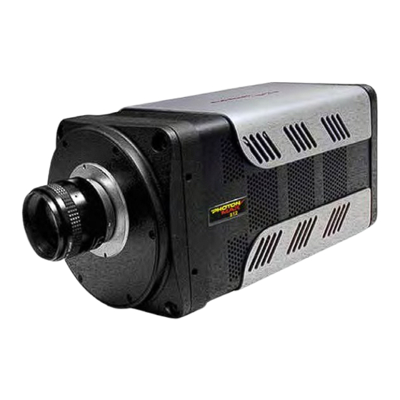
Related Manuals for Princeton Instruments PhotonMAX System


Summary of Contents for Princeton Instruments PhotonMAX System
- Page 1 4411-0107 Version 1.B January 26, 2006 *4411-0107*...
- Page 2 The information in this publication is believed to be accurate as of the publication release date. However, Princeton Instruments does not assume any responsibility for any consequences including any damages resulting from the use thereof. The information contained herein is subject to change without notice.
-
Page 3: Table Of Contents
Table of Contents Chapter 1 Introduction..................7 PhotonMAX™ Cameras ..................... 7 EMCCD Technology and On-Chip Multiplication Gain ............ 7 Integrated Controller......................8 Grounding and Safety ......................8 Precautions.......................... 9 UV Coating ......................... 9 Cleaning ..........................9 Repairs ..........................10 About this Manual ......................10 Chapter 2 System Component Descriptions .......... - Page 4 PhotonMAX System Manual Version 1.B Chapter 7 Troubleshooting ................67 Introduction........................67 Baseline Signal Suddenly Changes................... 68 Camera Stops Working ..................... 68 Camera1 (or similar name) in Camera Name field ............68 Controller Is Not Responding ................... 69 Cooling Troubleshooting ....................70 Data Overrun Due to Hardware Conflict message............
- Page 5 Figure 11. Cleans tab page....................27 Figure 12. RSConfig dialog box ..................27 Figure 13. Hardware Setup wizard: PVCAM dialog box ..........28 Figure 14. Block Diagram of PhotonMAX System............29 Figure 15. Controller/Camera tab page................31 Figure 16. Cleans tab page....................32 Figure 17.
- Page 6 PhotonMAX System Manual Version 1.B Figure 58. Hardware Wizard: Interface dialog box ............72 Figure 59. RSConfig dialog box ..................72 Figure 60. Hardware Wizard: PVCAM dialog box ............73 Figure 61. Hardware Wizard: Interface dialog box ............73 Figure 62. RSConfig dialog box: Two Camera Styles ............ 74 Figure 63.
-
Page 7: Chapter 1 Introduction
Chapter 1 Introduction Thank you for purchasing a PhotonMAX camera system from Princeton Instruments/ Acton. Your system has been thoroughly tested to meet the exacting standards of PI/Acton and to meet the demanding requirements of many low light level imaging applications. -
Page 8: Integrated Controller
These signals include extensive capabilities for synchronizing the operation of the PhotonMAX system with the rest of your experiment. The controlling electronics also collect the analog signal from the CCD, digitize it, and send it to the computer. -
Page 9: Precautions
Chapter 1 Introduction Precautions To prevent permanently damaging the system, please observe the following precautions: • The CCD array is very sensitive to static electricity. Touching the CCD can destroy it. Operations requiring contact with the device can only be performed at the factory. -
Page 10: Repairs
Version 1.B Repairs Because the PhotonMAX camera system contains no user-serviceable parts, repairs must be performed by Princeton Instruments. Should your system need repair, contact Princeton Instruments customer support for instructions. For contact information, refer to page 94 of this manual. - Page 11 Chapter 1 Introduction Safety Related Symbols Used in this Manual Caution! The use of this symbol on equipment indicates that one or more nearby items should not be operated without first consulting the manual. The same symbol appears in the manual adjacent to the text that discusses the hardware item(s) in question.
- Page 12 PhotonMAX System Manual Version 1.B This page intentionally left blank.
-
Page 13: Chapter 2 System Component Descriptions
System Components Standard Components A typical air-cooled PhotonMAX system consists of the camera, a power supply with power cable, a PCI card for your computer, a data cable, an I/O cable, and the user manual. A typical liquid-cooled system consists of the camera, a coolant circulator with hoses, a PCI card for your computer, a data cable, power cable, an I/O cable, and the user manual. -
Page 14: Coolcube Coolant Circulator
PhotonMAX System Manual Version 1.B Cooling: Dark current is reduced in PhotonMAX camera systems through thermoelectric cooling of the CCD arrays. Cooling by this method uses a four-stage Peltier cooler in combination with air-circulation or circulating coolant. To prevent condensation and contamination from occurring, cameras cooled this way are evacuated. -
Page 15: Cables
Serial numbers (useful if you ever need to contact Princeton Instruments Customer Support). User Manuals PhotonMAX System User Manual: This manual describes how to install and use the PhotonMAX camera and its components. WinView/32 User Manual: This manual describes how to install and use the application program. -
Page 16: Optional Components
WinView/32 or WinSpec/32, Princeton Instrument's 32-bit Windows® software packages designed specifically for high-end imaging and spectroscopy, respectively. The Princeton Instruments' software provides comprehensive image/spectral capture and display functions. The package also facilitates snap-ins to permit advanced operation. Using the optional built-in macro record function, you can also create and edit your own macros to automate a variety of operations. -
Page 17: Chapter 3 Installation Overview
Chapter 3 Installation Overview The list and diagrams below briefly describe the sequence of actions required to install your system and prepare to gather data. Refer to the indicated references for more detailed information. Action Reference 1. If the system components have not already been unpacked, unpack Chapter 4 System Setup, them and inspect their carton(s) and the system components for page 21... -
Page 18: Figure 3. Typical Imaging Experiment Layout With Air-Cooled Camera
PhotonMAX System Manual Version 1.B Action Reference 14. Adjust the focus for the best image or spectral lines. If you are using Chapter 5 Operation, WinSpec/32, you may want to use the Focus Helper function for page 30 or page 35 spectroscopy applications. -
Page 19: Figure 5. Typical Imaging Experiment Layout With Liquid-Cooled Camera
Chapter 4 System Component Descriptions Figure 5. Typical Imaging Experiment Layout with Liquid-cooled Camera Figure 6. Typical Spectroscopy Experiment Layout with Liquid-cooled Camera... - Page 20 PhotonMAX System Manual Version 1.B This page intentionally left blank.
-
Page 21: Chapter 4 System Setup
Keep all the original packing materials so you can safely ship the PhotonMAX system to another location or return it for service if necessary. If you have any difficulty with any step of the instructions, call Princeton Instruments Customer Support. -
Page 22: Checking The Equipment And Parts Inventory
Camera • Power Supply (or a CoolCUBE coolant circulator for liquid-cooled versions) • Host Computer: Can be purchased from Princeton Instruments or provided by user. • Computer Interface Components: • Data cable: 15 ft (5 meter) cable (6050-0545) is standard. -
Page 23: Attaching A Lens To A C- Mount Adapter
PhotonMAX cameras for imaging applications incorporate an integral C-mount adapter. Other mounts may be available. Consult the factory for specific information relating to your needs. See page 94 for Information on accessing the Princeton Instruments Customer Support Dept. Mounting the Lens C-mount lenses simply screw into the front of these cameras. -
Page 24: Adjusting The C-Mount Adapter
PhotonMAX System Manual Version 1.B Adjusting the C-Mount Adapter (2) Spanner Wrench Holes .10" (2.5 mm) dia x.15" (3.8 mm) deep Figure 7. Adjustable C-Mount Adapter The PhotonMAX features an adjustable C-mount adapter that allows you to change the focal depth. Use the hex key supplied with your system (or a .050" hex key) to adjust the adapter: loosen the three setscrews, rotate the ring to the desired height and tighten the screws to lock the adapter in place. -
Page 25: Software Installation
Chapter 4 System Setup Software Installation Notes: 1. If you have multiple cameras from Roper Scientific (PI and PM brands) on the same host computer, it may be necessary to edit the PVCAM.INI file. Refer to Chapter 7 for instructions. 2. -
Page 26: Entering The Default Camera System Parameters Into Winx (Winview/32, Winspec/32, Or Winxtest/32)
1. Make sure the PhotonMAX is connected to the host computer and that it is turned on. 2. Run the WinX application. The Camera Detection wizard will automatically run if this is the first time you have installed a Princeton Instruments WinX application (WinView/32, WinSpec/32, or WinXTest/32) and a supported camera. Otherwise, if you installing a new camera type, click on the Launch Camera Detection Wizard…... -
Page 27: Figure 10. Controller/Camera Tab
Chapter 4 System Setup Select "Clear Pre-Sequence" Select "Frame Transfer" Figure 10. Controller/Camera tab Figure 11. Cleans tab page page WinX Versions before 2.5.19.6: Run RSConfig.exe 1. Make sure the PhotonMAX is connected to the host computer and that it is turned on. 2. -
Page 28: Figure 13. Hardware Setup Wizard: Pvcam Dialog Box
PhotonMAX System Manual Version 1.B Controller/Camera tab page will be displayed with the Use PVCAM checkbox selected. Figure 13. Hardware Setup wizard: PVCAM dialog box 6. After making the following selections on the Controller/Camera tab page, you should now be able to control the camera and acquire data at the default Detector Temperature setting: On the Controller/Camera tab page: Select "Frame Transfer"... -
Page 29: Chapter 5 Operation
Acquire) that has been selected in the application Figure 14. Block Diagram of software. In WinView and WinSpec, these operations PhotonMAX System use the Experiment Setup parameters to establish the exposure time (the period when signal of interest is allowed to accumulate on the CCD). -
Page 30: First Light (Imaging)
PhotonMAX System Manual Version 1.B to be stored, data overflow will eventually occur. This could only happen in Fast Mode operation. The remainder of this chapter provides "First Light" procedures (these provide step-by- step instruction on how to initially verify system operation) and discusses factors that affect exposure, readout, and digitization of the incoming signal. -
Page 31: Figure 15. Controller/Camera Tab
Chapter 5 Operation Setting the Parameters Note: The following procedure is based on WinView/32: you will need to modify it if you are using a different application. Basic familiarity with the WinView/32 software is assumed. If this is not the case, you may want to review the software manual or have it available while performing this procedure. -
Page 32: Figure 16. Cleans Tab
PhotonMAX System Manual Version 1.B Select "Clear Pre-Sequence" Figure 16. Cleans tab page Detector Temperature (Setup|Detector Temperature…): The default temperature setting is read from the camera. When the array temperature reaches the set temperature, the Detector Temperature dialog box will report that the temperature is LOCKED . -
Page 33: Figure 18. Experiment Setup|Timing Tab
Chapter 5 Operation • Clicking on Full loads the full size of the chip into the edit boxes. Experiment Setup|Timing tab page (Acquisition|Experiment Setup…): • Timing Mode: Free Run • Shutter Control: Normal • Safe Mode vs. Fast Mode: Fast Mode Select "Fast Mode"... - Page 34 PhotonMAX System Manual Version 1.B 16-bit A/D is at full scale when the brightest parts of the image reach an intensity of 65535. Adjust the aperture to where it is just slightly smaller (higher f-stop) than the setting where maximum brightness on any part of the image occurs.
-
Page 35: First Light (Spectroscopy)
Chapter 5 Operation First Light (Spectroscopy) The following paragraphs provide step-by-step instructions for operating PhotonMAX in a spectroscopy setup for the first time. The intent of this simple procedure is to help you gain basic familiarity with the operation of your system and to show that it is functioning properly. -
Page 36: Figure 19. Controller/Camera Tab
PhotonMAX System Manual Version 1.B • Controller type: This information is read from the camera. • Camera type: This information is read from the camera. • Shutter type: Custom (System dependent). • Readout mode: Available modes are read from the camera. Select Frame Transfer. -
Page 37: Figure 21. Cleans Tab
Chapter 5 Operation Cleans tab page (Setup|Hardware): Select Clear Pre-Sequence as the Clean Mode. Select "Clear Pre-Sequence" Figure 21. Cleans tab page Experiment Setup|Main tab page (Acquisition|Experiment Setup…): • Exposure Time: 100 ms • Accumulations & Number of Images: 1 Experiment Setup|ROI tab page (Acquisition|Experiment Setup…): Use this function to define the region of interest (ROI). -
Page 38: Figure 22. Experiment Setup|Timing Tab
PhotonMAX System Manual Version 1.B Select "Fast Mode" Figure 22. Experiment Setup|Timing tab page Focusing The mounting hardware provides two degrees of freedom, focus and rotation. In this context, focus means to physically move the camera back and forth through the focal plane of the spectrograph. - Page 39 Chapter 5 Operation 4. In WinSpec, select Focus (on the Acquisition menu or on the Experiment Setup dialog box) to begin data accumulation. Data will be continuously acquired and displayed but will not be stored until you stop acquisition and use the Save function on the File menu.
-
Page 40: Exposure And Signal
PhotonMAX System Manual Version 1.B Exposure and Signal Exposure Time Exposure time (set on the Experiment Setup|Main tab page) is the time between commands sent by the application software to start and stop signal accumulation on the CCD. In combination with triggers, these commands... -
Page 41: Figure 24. Setting The Avalanche Gain (Experiment Setup|Main Tab Page)
Chapter 5 Operation Avalanche Gain (Multiplication Gain) As explained previously, the PhotonMAX uses a unique CCD capable of multiplying the charge (electrons) generated in the pixels. When the multiplication is sufficiently high, it is possible to see extremely low-light events. The amount of multiplication is controlled by the voltage applied to multiplication register clocks. - Page 42 For more information, refer to the "On-Chip Multiplication Gain" technical note. This technical note can be accessed by going to the Princeton Instruments web site at www.piacton.com. CCD Temperature As stated before, lowering the temperature of the CCD will generally enhance the quality of the acquired signal.
-
Page 43: Figure 27. Selecting The Clean Mode (Hardware Setup|Cleans Tab Page)
Caution If you observe a sudden change in the baseline signal, there may be excessive humidity in the camera vacuum enclosure. Turn off the camera and contact Princeton Instruments Customer Support. See page 94 for contact information. Offset (Bias) CCD cameras are typically designed to produce a certain level of offset (also known as bias) when no light is present and the exposure time is set to zero (0). -
Page 44: Readout
PhotonMAX System Manual Version 1.B • Clear Post-Sequence: Cleans continuously after the data acquisition sequence ends. The camera continues cleaning until a new exposure is set up or started, the abort command is sent, the speed entry number is changed, or the camera is reset. -
Page 45: Figure 29. Selecting The Readout Port (Experiment Setup|Main Tab Page)
Chapter 5 Operation Port #1: Multiplication Gain amplifier Port #2: Normal amplifier If your camera is configured with two readout amplifiers (ports), the software automatically allows port selection (Multiplication Gain or Normal). An example of a software dialogue to select the ports is shown in Figure 29. Readout Port selection Figure 29. -
Page 46: Figure 30. Selecting The Controller Gain (Experiment Setup|Adc Tab Page)
PhotonMAX System Manual Version 1.B Note: Since the first pixel to be read out from the Normal port is at the bottom right (closest to the Normal port), the resulting image is a mirror image of the same image if it were read out of the Multiplication Gain port. Some software packages do a "horizontal-flip"... -
Page 47: Figure 31. Selecting The Readout Rate (Experiment Setup|Adc Tab Page)
Chapter 5 Operation Readout Rate PhotonMAX has two readout rates available on each of the two ports. Selected on the Acquisition|Experiment Setup…|ADC tab page, a slower readout rate can be used when better noise performance is needed at the expense of frame rate. -
Page 48: Figure 32. Binning And Array Orientation
PhotonMAX System Manual Version 1.B Output Serial Register to A4 to A4 to B4 to C4 to D4 to D1 Parallel Mode Perpendicular Mode (binning occurs in (binning occurs in Output) Serial Register) Figure 32. Binning and Array Orientation You can easily switch between these orientations by rotating the camera 90° and changing the binning parameters in the application software. -
Page 49: Figure 33. Required Selections For Overlap Mode Operation
Chapter 5 Operation Select 2 or more Images/Spectra. Select the Select the "Frame Transfer" "Clear Pre-Sequence" Readout Mode. Set to Fast Mode. Clean Mode. Figure 33. Required Selections for Overlap Mode Operation Note: In Overlap mode, the minimum effective exposure time is the readout time. The simultaneous exposure-readout mechanism is illustrated with two examples. - Page 50 PhotonMAX System Manual Version 1.B Example 2: Overlap Mode when Exposure Time > Readout Time If the exposure time is set to 50 ms with the readout time remaining at 34.8 ms, the time taken to acquire 3 frames will be 184.8 ms (3 × 50 ms + 34.8 ms), which is equivalent to a frame rate of 16.2 fps.
-
Page 51: Figure 36. Required Selections For Non-Overlap Mode Operation
Chapter 5 Operation Non-Overlap Mode The Non-Overlap mode allows you to expose the array for the exposure time specified in the software and is similar in performance to a normal, full-frame device. The operational sequence for this mode is: 1. Clearing the CCD, 2. -
Page 52: Figure 37. Timing Diagram For Non-Overlap Mode
PhotonMAX System Manual Version 1.B Example: Non-Overlap Mode Operation in Non-Overlap mode is illustrated in the timing diagram below. In this example, the exposure time is 10 ms and the readout time is 34.8 ms. The total time to take 3 frames is 134.4 ms (3 × 10 ms + 3 × 34.8 ms), equivalent to a frame rate of 22.3 fps (3 frames ÷... -
Page 53: Chapter 6 Advanced Topics
Figure 38). "External Shutter Operation", the first topic covers some issues with regard to using an external shutter with a PhotonMAX system. "Timing Modes", the second topic, discusses Timing Modes, and Shutter Control. Also included under this topic is a discussion of the... -
Page 54: Timing Modes
PhotonMAX System Manual Version 1.B provide TTL output for the timing of an external shutter driver. This signal is high during Shutter Open Compensation Time (t ) and the Exposure Time (t The Shutter Output connector does not provide power to drive the shutter directly, so an external shutter drive controller is required. -
Page 55: Figure 40. Free Run Timing Diagram: Non-Overlap Mode
Chapter 6 Advanced Topics Free Run In Free Run mode, there is no external triggering and all settings are read from the setup parameters, making the duration of each exposure time constant and the interval times between exposures constant (see Figure 40). Exposure Frame Readout Figure 40. -
Page 56: Figure 43. Bulb Mode Timing Diagram: Non-Overlap Mode
PhotonMAX System Manual Version 1.B Bulb Trigger In Bulb Trigger mode, exposure time for each frame is determined by the trigger pulse width. Exposure time entered into the software is ignored in this mode (see Figure 43). If a trigger arrives during the readout of the previous frame, it is ignored. The shaded areas denote the idle time between exposures. -
Page 57: Fast And Safe Modes
Chapter 6 Advanced Topics Fast and Safe Modes Introduction The PhotonMAX has been designed to allow the greatest possible flexibility when synchronizing data collection with an experiment. The fundamental difference between the Fast and Safe modes is how often the acquisition start and acquisition stop commands are sent by the computer for a data collection sequence. -
Page 58: Figure 46. Flowcharts Of Safe And Fast Mode Operation
PhotonMAX System Manual Version 1.B Safe Mode Fast Mode Start Start Computer programs Computer programs camera with exposure camera with exposure and binning parameters and binning parameters Sequence start Sequence start command issued by command issued by computer to camera... -
Page 59: Ttl Status Signals
Chapter 6 Advanced Topics TTL Status Signals The I/O (Input/Output Status) connector on the rear of the PhotonMAX provides information about trigger function, DAC, and TTL signals. Inputs must be at least 3.15 V for a high and less than 0.9 V for a low. -
Page 60: Kinetics Mode (Option)
PhotonMAX System Manual Version 1.B Kinetics Mode (Option) Introduction “Kinetics” refers to a special readout mode in which a portion of the CCD is illuminated while the rest of the active area is used to store a series of frames. -
Page 61: Figure 50. Two Examples Illustrating Partial Illumination Of Ccd For Kinetics Mode
Chapter 6 Advanced Topics Figure 50. Two Examples illustrating Partial Illumination of CCD for Kinetics Mode Note: The illuminated area is the furthest from the serial register. • The left image shows an illuminated area of 60 rows. Window Size is 60 rows high. •... -
Page 62: Figure 52. Experiment Setup| Timing Tab
PhotonMAX System Manual Version 1.B Notes: 1. The timing diagram represents the exposure-readout sequence. Time resolution between subframes is given by t 2. A reduced number of rows in the right image illustrate a way to achieve better time resolution between subframes. -
Page 63: Figure 54. Example Showing Kinetics Operation Using "Multiple Trigger
Chapter 6 Advanced Topics In multiple trigger mode, each “exposure-shift” cycle is triggered independently. This mode is useful when each subframe needs to be synchronized with a pulsed external light source such as a laser. Trigger In Exposure/ ß à ß... -
Page 64: Figure 55. Typical Kinetics Experiment Layout
PhotonMAX System Manual Version 1.B Setting up a Kinetics Experiment Figure 55. Typical Kinetics Experiment Layout This procedure assumes that: 1. You have already set up your system in accordance with the instructions in the previous chapters. 2. You have read the previous sections of this chapter. - Page 65 Chapter 6 Advanced Topics Cleans tab page (Setup|Hardware): Automatically set. Detector Temperature (Setup|Detector Temperature…): The default temperature setting is read from the camera. When the array temperature reaches the set temperature, the Detector Temperature dialog box will report that the temperature is LOCKED . Experiment Setup|Main tab page (Acquisition|Experiment Setup…): •...
- Page 66 PhotonMAX System Manual Version 1.B This page intentionally left blank.
-
Page 67: Chapter 7 Troubleshooting
Chapter 7 Troubleshooting WARNING! Do not attach or remove any cables while the camera system is powered on. Introduction The following issues have corresponding troubleshooting sections in this chapter. Baseline Signal Suddenly Changes Page 68 Camera Stops Working Page 68 Camera1 (or similar name) in Camera Name field Page 68 Controller Is Not Responding... -
Page 68: Baseline Signal Suddenly Changes
If you hear 2 clicks separated by 1 second (shutter opening then closing), the shutter is working. Call Princeton Instruments Customer Support for further instructions. If the system still does not respond, contact Princeton Instruments Customer Support. Camera1 (or similar name) in Camera Name field Figure 56. Camera1 in Camera Name Field... -
Page 69: Controller Is Not Responding
Chapter 7 Troubleshooting 2. Change the "Name=" entry to something more meaningful for you (for example, PhotonMAX-spec- to indicate that this is a PVCAM-based system using a PhotonMAX camera for spectroscopy). Then save the edited file. [Camera_1] Type=0 Name=PhotonMAX-spec Driver=pmwdm2k.sys Port=0 3. -
Page 70: Cooling Troubleshooting
PhotonMAX System Manual Version 1.B Cooling Troubleshooting Temperature Lock Cannot be Achieved or Maintained. Possible causes for not being able to achieve or maintain lock could include: • Ambient temperature greater than +25°C. This condition affects TE-cooled cameras. If ambient is greater than +25°C, you will need to cool the camera environment or raise the set temperature. -
Page 71: Data Overrun Due To Hardware Conflict Message
Chapter 7 Troubleshooting thermal-protection switch that shuts the cooler circuits down if the internal temperature exceeds a preset limit. Typically, camera operation is restored automatically in about ten minutes. Although the thermo-protection switch will protect the camera, you are nevertheless advised to power down and correct the operating conditions that caused the thermal-overload to occur. -
Page 72: Figure 58. Hardware Wizard: Interface Dialog Box
PhotonMAX System Manual Version 1.B Figure 58. Hardware Wizard: Interface dialog box At this point, you will need to exit WinView and run the RSConfig.exe program, which creates a file called PVCAM.INI. This file contains information required to identify the... -
Page 73: Demo, High Speed Pci, And Pci(Timer) Are Choices On Hardware Wizard:interface Dialog (Versions 2.5.19.0 And Earlier)
Demo, High Speed PCI, and PCI(Timer) are Choices on Hardware Wizard:Interface dialog (Versions 2.5.19.0 and earlier) If there is an installed Princeton Instruments (RSPI) high speed card in the host computer and you want to operate a PhotonMAX camera, the PVCAM.INI file (created by RSConfig.exe) must exist and the PhotonMAX camera (PM Style) must be [Camera_1]. -
Page 74: Detector Temperature, Acquire, And Focus Are Grayed Out (Versions 2.5.19.0 And Earlier)
PVCAM and have opened WinView/32 or WinSpec/32 without having first turned on the PhotonMAX camera. They will also be deactivated if you have installed a camera being run PVCAM and a Princeton Instruments (RSPI) high speed PCI card was also detected when RSConfig.exe was run. -
Page 75: Editing The Pvcam.ini File
Chapter 7 Troubleshooting Figure 63. RSConfig dialog box: Two Camera Styles Editing the PVCAM.INI File 1. Using Notepad or a similar text editor, open PVCAM.INI, which is located in the Windows directory (C:\WINNT, for example). If the contents of the file look like: Change the headings so the contents now look like: [Camera_1] [Camera_2]... -
Page 76: Error Creating Controller Message
PhotonMAX System Manual Version 1.B Error Creating Controller message This message may be displayed if you are using a PVCAM-supported camera and have not run the RSConfig.exe program (see previous topic), if the PVCAM.INI file has been corrupted, or if the PhotonMAX was not powered on before you started WinView/32 or WinSpec/32 and began running the Hardware Wizard. -
Page 77: Serial Violations Have Occurred. Check Interface Cable
Chapter 7 Troubleshooting 6. Reboot your computer. 7. Restart WinView and begin acquiring data or focusing. If you see the message again, increase the DMA buffer size. Serial violations have occurred. Check interface cable. Figure 67. Serial Violations Have Occurred dialog box This error message dialog will appear if you try to acquire an image or focus the camera and either (or both) of the following conditions exists: •... - Page 78 PhotonMAX System Manual Version 1.B This page intentionally left blank.
-
Page 79: Declaration Of Conformity
Declaration of Conformity This section of the PhotonMAX system manual contains the declaration(s) of conformity for PhotonMAX systems. - Page 80 DECLARATION OF CONFORMITY ROPER SCIENTIFIC (PRINCETON INSTRUMENTS) 3660 QUAKERBRIDGE ROAD TRENTON, NJ 08619 Declare under our sole responsibility, that the product, PhotonMAX CAMERA, To which this declaration relates, is in conformity with general safety requirement for electrical equipment standards: IEC 1010-1:1990, EN 61010-1:1993/A2:1995,...
- Page 81 This page intentionally left blank.
- Page 82 PhotonMAX System Manual Version 1.B This page intentionally left blank.
-
Page 83: Appendix A Basic Specifications
Digitization (Readout) Rate: Note: The arrays listed are those that were available at the time that the manual was written. Contact Princeton Instruments for an updated list of arrays supported by the PhotonMAX. Mounts C-mount: Standard threaded video mount. Optional C- to Spectroscopy-mount adapter. - Page 84 PhotonMAX System Manual Version 1.B Gain: Software-selectable [1 (low), 2 (medium), 3 (high)] Dimensions: See Appendix B, "Outline Drawings", pages 87 and 88. Connectors: Data: 20-pin, high-density connector (MDR-20) for data transfer. I/O: 26-pin, high-density connector (DB26) for TTL status signals).
- Page 85 Appendix A Basic Specifications PORT # PIN # SIGNAL Description Trigger Input: This input is internally tied high through a 4.7kΩ resistor. With Trigger Invert Input open or tied high, a rising edge of the Trigger Input signal initiates the trigger. The trigger source would normally hold this input low, then drive it high to initiate the trigger.
-
Page 86: Coolcube Circulator
PhotonMAX System Manual Version 1.B PORT # PIN # SIGNAL Description (not used) (not used) Shutter Output: TTL output for timing of external shutter driver. Signal is high during Shutter Open Compensation Time and exposure time. The pin does not provide power to drive the shutter directly, so an external shutter drive controller is required. -
Page 87: Appendix B Outline Drawings
Appendix B Outline Drawings Note: Dimensions are in inches [mm]. PhotonMAX Camera: C-mount, Air-Cooled... -
Page 88: Photonmax Camera: C-Mount, Liquid-Cooled
PhotonMAX System Manual Version 1.B PhotonMAX Camera: C-mount, Liquid-Cooled... -
Page 89: Coolcube Circulator
Appendix B Outline Drawings CoolCUBE Circulator... - Page 90 PhotonMAX System Manual Version 1.B This page intentionally left blank.
-
Page 91: Warranty & Service
Instruments will repair the product or, at its sole option, repair or replace any defective part without charge to you. You must deliver the entire product to the Princeton Instruments factory or, at our option, to a factory-authorized service center. You are responsible for the shipping costs to return the product. - Page 92 Basic Limited One (1) Year Warranty. Vacuum Integrity Limited 24 Month Warranty Princeton Instruments warrants the vacuum integrity of all our products for a period of up to twenty-four (24) months from the date of shipment. We warrant that the detector head will maintain the factory-set operating temperature without the requirement for customer pumping.
- Page 93 (1) year limited warranty and/or any other warranty, expressed or implied. 3. All warranty service must be made by the Princeton Instruments factory or, at our option, an authorized service center. 4. Before products or parts can be returned for service you must contact the Princeton Instruments factory and receive a return authorization number (RMA).
-
Page 94: Contact Information
In no event shall Princeton Instruments' liability exceed the cost of the repair or replacement of the defective product or part. -
Page 95: Index
Index Clear never...............43 Clear post-sequence..........44 AC power requirements...........22 Clear pre- and post-sequence........44 Accessories, alignment of........39 Clear pre-exposure...........43 Acquisition functions grayed out......74 Clear pre-exposure and post-sequence ....44 Air-circulation requirement ........14 Clear pre-sequence ..........43 Background DC level ..........43 C-mount Baseline adapters ...............23 signal ..............43 lens installation/removal ........23 troubleshooting............68... - Page 96 PhotonMAX System Manual Version 1.B External shutter............53 POWER connector External Sync mode..........55 LEMO ..............14 pinout ..............84 Power cord...............22 Fast mode..............57 Power requirements ..........22 data acquisition............57 Program Error message ...........76 flowchart .............58 PVCAM.INI ............68 image update lag ..........57 First light ............30, 35 Focusing, alignment..........38...
- Page 97 Index Timing modes............54 bulb trigger ............56 Vacuum deterioration ..........71 External Sync ............55 Ventilation requirements .........22 Free Run..............55 Warnings single trigger............56 cleaning ..............9 Traditional amplifier..........45 protective grounding ..........8 Trigger modes replacement powercord .........8 bulb trigger ............56 touching the CCD array.........9 External Sync ............55 Warranties multiple trigger (Kinetics)........63 image intensifier detector ........92...
- Page 98 PhotonMAX System Manual Version 1.B This page intentionally left blank.
Need help?
Do you have a question about the PhotonMAX System and is the answer not in the manual?
Questions and answers