Table of Contents
Advertisement
Advertisement
Table of Contents

Related Manuals for Elation FUZE PROFILE CW


Summary of Contents for Elation FUZE PROFILE CW
- Page 1 FUZE PROFILE CW™ user manual...
- Page 2 +31 45 546 85 66 | +31 45 546 85 96 fax | www.elationlighting.eu | info@elationlighting.eu Elation Professional Mexico | AV Santa Ana 30 | Parque Industrial Lerma, Lerma, Mexico 52000 +52 (728) 282-7070 D O C U M E N T V E R S I O N...
-
Page 3: Table Of Contents
C O N T E N T S General Information Warranty Returns (USA Only) Safety Guidelines Maintenance Guidelines Fixture Overview Colors and Gobos Custom Gobos Gobo Replacement Snoot Installation Installation Guidelines System Menu DMX Channel Functions and Values Error Codes Specifications Optional Accessories... -
Page 4: General Information
Snoot Omega Brackets (x2) Neutrik powerCON TRUE1 Power Cable CUSTOMER SUPPORT Contact ELATION Service for any product related service and support needs. Also visit forums.elationlighting.com with questions, comments or suggestions. ELATION SERVICE USA - Monday - Friday 8:00am to 4:30pm PST 323-582-3322 | Fax 323-832-9142 | support@elationlighting.com... -
Page 5: Warranty Returns (Usa Only)
ELATION in Los Angeles, CA or to an ELATION Authorized Service Center. The RMA number must be clearly written on the outside of the return box and a brief description of the problem and the RMA number must be documented and included in the box. -
Page 6: Safety Guidelines
This fixture is a sophisticated piece of electronic equipment. To guarantee a smooth operation, it is important to follow all instructions and guidelines in this manual. Elation Professional is not responsible for injury and/or damages resulting from the misuse of this fixture due to the disregard of the information printed in this manual. - Page 7 S A F E T Y G U I D E L I N E S DO NOT TOUCH the fixture housing during operation. Turn OFF the power and allow approximately 15 minutes for the fixture to cool down before serving. DO NOT shake fixture, avoid brute force when installing and/or operating fixture.
-
Page 8: Maintenance Guidelines
Regular inspections are recommended to insure proper function and extended life. There are no user serviceable parts inside this fixture, please refer all other service issues to an authorized Elation service technician. Should you need any spare parts, please order genuine parts from an authorized Elation dealer. -
Page 9: Fixture Overview
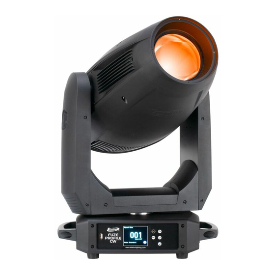
F I X T U R E O V E R V I E W Lens Tilt Lock Pan Lock System Menu Display Power In/Out Menu Navigation Buttons Fuze Service Port 5pin DMX In/Out SAFETY CABLE ATTACHMENT POINT ALWAYS ATTACH A SAFETY CABLE WHENEVER INSTALLING THIS DEVICE IN A SUSPENDED ENVIRONMENT TO ENSURE THE FIXTURE WILL NOT DROP IF THE CLAMP FAILS. -
Page 10: Colors And Gobos
C O L O R S A N D G O B O S Color Wheel 1 Slot Color Name Medium Green Light Blue Lavender Amber Light Pink Warm Yellow Color Wheel 2 Slot Color Name 2700K 3200K 4500K 5500K 6800K 8000K INTERCHANGEABLE-ROTATING GLASS GOBOS... -
Page 11: Custom Gobos
Extended testing of custom gobo designs is highly recommended prior to use. Contact ELATION SERVICE for further information. ELATION SERVICE USA - Monday - Friday 8:00am to 4:30pm PST 323-582-3322 | Fax 323-832-9142 | support@elationlighting.com... - Page 12 O B G O B O R E P L A C E M E N T Tilt Lock Pan Lock 1. Before removing covers, place fixture on a stable flat surface in an INDOOR DUST FREE location. Ensure moving head is locked into a neutral upright position with both PAN and TILT locks engaged.
-
Page 13: Gobo Replacement
G O B O R E P L A C E M E N T 3. The GOBO Wheel module is secured to the fixture frame rail with (2x) slotted thumb screws. Before you can remove it, the fan needs to be removed, which is held in place with (2x) integrated Phillips screws. 4. - Page 14 G O B O R E P L A C E M E N T To remove the module, loosen the (2x) slotted screws holding the brackets. 7. Carefully grip the GOBO Wheel module and slid it out and away to clear the mounting rails. 8.
- Page 15 G O B O R E P L A C E M E N T 7. REPLACING A ROTATING GOBO - Locate the specific Rotating GOBO to replace. Carefully gripping the GOBO using your index finger, gently lift it slightly, and then with a pair of needle-nose pliers, pull on the tab to pull it out and away until it fully clears the GOBO Wheel.
-
Page 16: Snoot Installation
S N O O T I N S T A L L A T I O N 4-Ø3.5mm [Ø0.14in] Ø148mm [Ø5.83in] snoot Ø136mm [Ø5.35in] 1. Place fixture on the stable flat surface and let cool for 15mins. 2. Align snoot onto front lens so screw holes on snoot match screw holes on lens. 3. -
Page 17: Installation Guidelines
I N S T A L L A T I O N G U I D E L I N E S FLAMMABLE MATERIAL WARNING Keep fixture minimum 5.0 feet (1.5m) away from flammable materials and/or pyrotechnics. ELECTRICAL CONNECTIONS A qualified electrician should be used for all electrical connections and/or installations. USE CAUTION WHEN POWER LINKING OTHER MODEL FIXTURES AS THE POWER CONSUMPTION OF OTHER MODEL FIXTURES MAY EXCEED THE MAX POWER OUTPUT ON THIS FIXTURE. - Page 18 I N S T A L L A T I O N G U I D E L I N E S OMEGA BRACKETS INSTALLATION Insert the Omega Brackets into the matching holes on the bottom of the fixture. Secure the Omega Brackets to the fixture by turning each quick-lock fastener ¼...
- Page 19 LEDs. This issue is not specific only to ELATION lighting fixtures, it is a common issue with lighting fixtures from all manufacturers. Although there is no true way to fully prevent this issue from happening, the guidelines below can prevent any potential damage from occurring if followed.
-
Page 20: System Menu
S Y S T E M M E N U The fixture includes an easy to navigate system menu. The LCD touch panel (see image below) located on the front of the fixture, provides access to the main system menu and is where all necessary system adjustments are made to the fixture. - Page 21 ELATION FUZE PROFILE CW™ - SYSTEM MENU Supports Software Versions: ≥ 1.03 A001 ~ AXXX DMX Address DMX Settings Standard, Extend DMX Channel Mode No DMX Status Hold Last, Blackout, Internal Programs Master ON / OFF Slave ON / OFF...
- Page 22 000-255 Pan Fine 000-255 Manual Tilt 000-255 Control Tilt Fine 000-255 ColorWheel1 000-255 Control 000-255 Speed 000-255 Program 0 Fade 000-255 Speed 000-255 Program 1 Fade 000-255 Internal Speed 000-255 Program 2 Fade 000-255 Programs Speed 000-255 Program 3 Fade 000-255 Speed 000-255...
-
Page 23: Dmx Channel Functions And Values
D M X C H A N N E L F U N C T I O N S A N D V A L U E S FUZE PROFILE CW™ - DMX Channel Values / Functions (40 DMX Channels) Supports Software Versions: ≥... - Page 24 MODE / CHANNEL VALUE FUNCTION DEFAULT SNAP Standard Extended Rotating Gobo Wheel Open 10-19 Gobo 1 20-29 Gobo 2 30-39 Gobo 3 40-49 Gobo 4 50-59 Gobo 5 60-69 Gobo 6 70-77 Gobo 7 78-93 Gobo 1 Shake, Slow to Fast 94-109 Gobo 2 Shake, Slow to Fast 110-125...
- Page 25 MODE / CHANNEL VALUE FUNCTION DEFAULT SNAP Standard Extended Dimmer 0-255 Intensity 0 → 100% Dimmer Fine 0-255 Dimmer Fine Dim Modes 0-20 Standard 21-40 Stage 41-60 61-80 Architectural 81-100 Theatre 101- 120 Stage 2 Dimmer Delay Time 0.1s 0.2s 0.3s 0.4s 0.5s...
- Page 26 MODE / CHANNEL VALUE FUNCTION DEFAULT SNAP Standard Extended Iris Fine 0-255 Iris Fine Frost 0-255 Open to Full Frost Blade 1A 0-255 Open to Close Blade 1A Fine 0-255 Open to Close Fine Blade 1B 0-255 Open to Close Blade 1B Fine 0-255 Open to Close Fine...
- Page 27 MODE / CHANNEL VALUE FUNCTION DEFAULT SNAP Standard Extended Framing Rotation 0-126 Min (-45 degrees) 127-128 Parallel (0 degrees) 129-255 Max (+45 degrees) Framing Rotation Fine 0-255 Framing Rotation Fine Pan / Tilt Speed 0-225 Max to Min Speed 226-235 Blackout by Movement 236-245 Blackout by all Wheel Changing...
- Page 28 MODE / CHANNEL VALUE FUNCTION DEFAULT SNAP Standard Extended 1090 1100 1110 1120 1130 1140 1150 1160 1170 1180 1190 1200 1210 1220 1230 1240 1250 1260 1270 1280 1290 1300 1310 1320 1330 1340 1350 1360 1370 1380 1390 1400 1410 1420...
- Page 29 MODE / CHANNEL VALUE FUNCTION DEFAULT SNAP Standard Extended 2500 4000 5000 6000 10,000 15,000 20,000 25,000 169-200 Idle 201-210 Dimmer Curve Linear (default) 211-220 Dimmer Curve Square 221-230 Dimmer Curve Inverse Square 231-240 Dimmer Curve S-Curve Internal Program 1 (Scene 1 - 8) Internal Program 2 (Scene 9 - 16) Internal Program 3 (Scene 17 - 24) Internal Program 4 (Scene 25 - 32)
-
Page 30: Error Codes
E R R O R C O D E S Error Codes subject to change without notice. ERROR CODES DESCRIPTION Movement is not located in the default position after the reset. PAN Er These messages will appear after a fixture reset if the magnetic- indexing circuit malfunctions (sensor failed, or magnet is missing) or there is a motor failure (defective motor or a defective motor IC drive on the main PCB). -
Page 31: Specifications
S P E C I F I C A T I O N S SOURCE 380W 6,000K White LED Engine. 91 CRI 30,000 Hour Average LED Life* *Test lab conditions. May vary depending on several factors including but not limited to: Environmental Conditions, Power/Voltage, Usage Patterns (On-Off Cycling), Control, and Dimming. - Page 32 DIMENSIONAL DRAWINGS 396mm(15.59in) 408mm(16.06in) 518.2mm(20.4in) 273.5mm(10.77in) 111mm(4.37in) 256mm(10.08in) Specifications and improvements in the design of this unit and this manual are subject to change without notice.
- Page 33 DIMENSIONAL DRAWINGS – With Snoot Attached Specifications and improvements in the design of this unit and this manual are subject to change without notice.
-
Page 34: Optional Accessories
O P T I O N A L A C C E S S O R I E S ORDER CODE ITEM TRIGGER CLAMP Heavy Duty Wrap Around Hook Style Clamp SIP126 5 ft. (1.5m) IP65 Twist Lock Power Link Cable AC5PDMX5PRO 5 ft. - Page 35 FCC STATEMENT This device complies with Part 15 of the FCC Rules. Operation is subject to the following two conditions: (1) this device may not cause harmful interference, and (2) this device must accept any interference received, including interference that may cause undesired operation. FCC RADIO FREQUENCY INTERFERENCE WARNINGS &...
Need help?
Do you have a question about the FUZE PROFILE CW and is the answer not in the manual?
Questions and answers