Table of Contents
Advertisement
Quick Links
Advertisement
Table of Contents

Related Manuals for Elation SOL I Blinder


Summary of Contents for Elation SOL I Blinder
- Page 1 I BLINDER user manual...
- Page 2 Elation Professional B.V. | Junostraat 2 | 6468 EW Kerkrade, The Netherlands +31 45 546 85 66 | +31 45 546 85 96 fax | www.elationlighting.eu | info@elationlighting.eu Elation Professional Mexico | AV Santa Ana 30 | Parque Industrial Lerma, Lerma, Mexico 52000 +52 (728) 282-7070...
-
Page 3: Table Of Contents
C O N T E N T S General Information IP65 Rated Limited Warranty (USA Only) Safety Guidelines Overview Torque Settings for Screws IP Test Parameters Installation Guidelines Accessory Installation Remote Device Management (RDM) Colourtune Technology System Menu System Menu Output Options Dimmer Mode Curves &... -
Page 4: General Information
(1) Safety Cable (1) IP65 Locking Power Cable CUSTOMER SUPPORT Contact ELATION Service for any product related service and support needs. Also visit forums.elationlighting.com with questions, comments or suggestions. ELATION SERVICE USA - Monday - Friday 8:00am to 4:30pm PST 323-582-3322 | Fax 323-832-9142 | support@elationlighting.com... -
Page 5: Ip65 Rated
I P 6 5 R AT E D The International Protection (IP) rating system is commonly expressed as “IP” (Ingress Protection) followed by two numbers (i.e. IP65), where the numbers define the degree of protection. The first digit (Foreign Bodies Protection) indicates the extent of protection against particles entering the fixture, and the second digit (Water Protection) indicates the extent of protection against water entering the fixture. -
Page 6: Limited Warranty (Usa Only)
It is the owner’s responsibility to establish the date and place of purchase by acceptable evidence, at the time service is sought. B. For warranty service, send the product only to the Elation Professional factory. All shipping charges must be pre-paid. If the requested repairs or service (including parts replacement) are within the terms of this warranty, Elation Professional will pay return shipping charges only to a designated point within the United States. -
Page 7: Safety Guidelines
This fixture is a sophisticated piece of electronic equipment. To guarantee a smooth operation, it is important to follow all instructions and guidelines in this manual. Elation Professional is not responsible for injury and/or damages resulting from the misuse of this fixture due to the disregard of the information printed in this manual. - Page 8 S A F E T Y G U I D E L I N E S DO NOT TOUCH the fixture housing during operation. Turn OFF the power and allow approximately 15 minutes for the fixture to cool down before serving. DO NOT shake fixture, avoid brute force when installing and/or operating fixture.
-
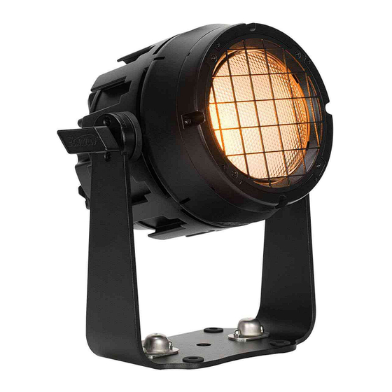
Page 9: Overview
O V E R V I E W... -
Page 10: Torque Settings For Screws
T O R Q U E S E T T I N G S F O R S C R E W S Front Lens Cover (13±0.5/Kgf.cm) Fixed Rear Cover (13±0.5/Kgf.cm) CAUTION! DO NOT OVER TORQUE SCREWS AS THIS CAN CAUSE LEAKAGE ISSUES! TO CONFIRM THE IP65 INTEGRITY, TEST FIXTURE USING THE ELATION IP TESTER. CONTACT ELATION SERVICE FOR MORE DETAILS. -
Page 11: Ip Test Parameters
Following any repair or maintenance procedure that requires disassembly of the fixture, use Elation’s IP Tester to confirm the IP integrity of the fixture. The air valve is located on the back panel next to the display screen, as shown in the diagram below. Please contact Elation... -
Page 12: Installation Guidelines
The SŌL I Blinder can be updated through the DMX cable using the C-Loader device, which can be purchased from Elation Professional. The latest software is available for download from the SŌL I BLINDER product page. Please... - Page 13 I N S TA L L AT I O N G U I D E L I N E S FIXTURE INSTALLATION The Elation SŌL I BLINDER is fully operational in three different mounting positions, hanging upside-down, mounted sideways on trussing, or set on a flat level surface. Be sure this fixture is kept at least 0.2m (7.9in.) away from any flammable materials (decoration etc.).
- Page 14 LEDs. This issue is not specific only to ELATION lighting fixtures, it is a common issue with lighting fixtures from all manufacturers. Although there is no true way to fully prevent this issue from happening, the guidelines below can prevent any potential damage from occurring if followed.
- Page 15 I N S TA L L AT I O N G U I D E L I N E S CLAMP INSTALLATION This device features a mounting clamp attachment point built into the mounting bracket, as well as a safety cable attachment point located on the rear face of the fixture above the control panel.
- Page 16 I N S TA L L AT I O N G U I D E L I N E S M10 CONNECT ADAPTER The M10 Connect Adapter enables the fixture to be suspended using various methods, including an M10 threaded rod, a C-clamp, or by direct bolting to another device. The inserted thread length should not exceed 15mm (0.59 inches).
- Page 17 I N S TA L L AT I O N G U I D E L I N E S VERTICAL INSTALLATION The Fixture Interconnect (depicted on the right) has a maximum suspension limit of 90lbs (40.8kg) in a vertical orientation, which accounts for all accessories, cables, and rigging hardware attached to the fixture array.
- Page 18 I N S TA L L AT I O N G U I D E L I N E S DESIGN CONFIGURATIONS The connector grooves on the Sol I Blinder are arranged in 30-degree intervals, like the spokes of a wheel, allowing for numerous design configurations. However, please note that subsequent fixtures can only be attached at 60-degree increments without physical interference.
- Page 19 I N S TA L L AT I O N G U I D E L I N E S REAR MOUNT BRACKET WITH TRUSS CLAMP A truss clamp can be attached to the SŌL I Blinder via a Rear Mount Bracket (not included), which is bolted directly to the rear panel as shown.
- Page 20 A C C E S S O R Y I N S TA L L AT I O N FLOOR STAND YOKE (INCLUDED) The Floor Stand/Yoke can support a maximum vertical load of 60 lbs (27.22 kg), or 9 SOL I Blinders without any additional accessories.
-
Page 21: Accessory Installation
A C C E S S O R Y I N S TA L L AT I O N BOWENS ADAPTER & ACCESSORY CONNECTOR (OPTIONAL) 1. Align the 3x holes on the Bowens Adapter with the Fixture and secure it with (3x) Phillips head screws 2. - Page 22 A C C E S S O R Y I N S TA L L AT I O N GEL FRAME HOLDER KIT (OPTIONAL) Note: The grid attached to the compound lens is purely for aesthetic purposes and can be removed if desired by removing 4x screws.
- Page 23 A C C E S S O R Y I N S TA L L AT I O N BARNDOOR (OPTIONAL) 1. Lift the retaining clip located near the top of the Gel Frame Holder. 2. Slide the barndoor into place in front of the Gel Frame.
-
Page 24: Remote Device Management (Rdm)
R E M O T E D E V I C E M A N A G E M E N T ( R D M ) NOTE: In order for RDM to work properly, RDM enabled equipment must be used through- out the entire system, including DMX data splitters and wireless systems. -
Page 25: Colourtune Technology
CCT and color settings with balanced fidelity and output. OUTPUT BALANCE Output Balance settings allow users to choose between Bright and Uniform (Elation Full Spectrum Match). This setting enables color tone balancing across multiple fixture models that also use Elation’s Full Spectrum Engine. -
Page 26: System Menu
Exit the main menu at any time without making any adjustments by pressing the MODE button. AN ELATION C-LOADER II CAN BE USED TO UPDATE THE FIXTURE TO THE LATEST SOFTWARE. TO ORDER THIS DEVICE, PLEASE CONTACT ELATION SUPPORT FOR FURTHER DETAILS. - Page 27 S YS T E M M E N U OPTIONS / VALUES MAIN MENU (Default Settings in BOLD) DMX Address 001 - 512 1CH Dimmer 2CH Dimmer & CCT 3CH Dim/Strb/CCT 4CH IRGB 6CH Raw Color 7CH Dim/CCT/Clr DMX Mode 13CH Standard 21CH Extended 10CH RGB...
- Page 28 6000Hz, 10KHz, 15KHz, 20KHz, 25KHz Settings Highest Fidelity Color Tuning Balanced Output and Fidelity Highest Output Bright (Highest Output) Output Balance Uniform (Elation Full Spectrum Match) LED Power Limit 100% 10s - 5min Screen Delay (Default = 1 min) Display...
-
Page 29: System Menu Output Options
S YS T E M M E N U - O U T P U T M O D E O P T I O N S Blinder Output (Default) In Blinder Output mode, the fixture operates at its maximum possible output while ensuring a safe operating temperature. -
Page 30: Dimmer Mode Curves & Graphs
D I M M E R M O D E C U R V E S & G R A P H S... -
Page 31: Dmx Traits
D M X T R A I T S Dim./ Dim. CCT/ Dim. & Strobe IRGB Std. Ext. Snap Default Color Color Ext. Ext. Function 13CH 21CH 10CH 10CH Values Value Picker 15CH 15CH Dimmer 0-255 Intensity 0 → 100% Dimmer Fine 0-255 Fine Intensity Control... - Page 32 D M X T R A I T S Dim./ Dim. CCT/ Dim. & Strobe IRGB Std. Ext. Snap Default Color Color Ext. Ext. Function 13CH 21CH 10CH 10CH Values Value Picker 15CH 15CH CCT Presets 0-17 Open 18-85 1800K → 8500K (See Sheet) 86-255 8500K Variable CCT 0-17...
- Page 33 D M X T R A I T S Dim./ Dim. CCT/ Dim. & Strobe IRGB Std. Ext. Snap Default Color Color Ext. Ext. Function 13CH 21CH 10CH 10CH Values Value Picker 15CH 15CH Control 0-24 Idle 25-34 Blinder Output Mode 35-44 Constant Output Mode 45-99...
- Page 34 175-176 Highest Fidelity 177-178 Balanced Output and Fidelity 179-180 Highest Output (Default) Output Balance 181-182 Bright (Highest Output) 183-184 Uniform (Elation Full Spectrum Match) 185-200 Idle Dimmer Curves 201-210 Dimmer Curve: Linear (Default) 211-220 Dimmer Curve: Square 221-230 Dimmer Curve: Inverse Square...
-
Page 35: Color Temperature
C O L O R T E M P E R AT U R E DMX VALUE COLOR TEMPERATURE (K) DMX VALUE COLOR TEMPERATURE (K) 1800 5700 1900 5800 2000 5900 2100 6000 2200 6100 2300 6200 2400 6300 2500 6400 2600 6500... -
Page 36: Virtual Colors
V I R T U A L C O L O R S VALUE FILTER # COLOR VALUE FILTER # COLOR Pale Yellow Mauve Straw Medium Purple Gold Tint Lavender Spring Yellow Palace Blue Medium Yellow Dark Blue Yellow Medium Blue Deep Amber Deep Blue Deep Straw... -
Page 37: Error Codes
E R R O R C O D E S Error Codes subject to change without notice ERROR CODES DESCRIPTION Temp Error This message appears when there is a heating error. -
Page 38: Maintenance Guidelines
Regular inspections are recommended to insure proper function and extended life. There are no user serviceable parts inside this fixture, please refer all other service issues to an authorized Elation service technician. Should you need any spare parts, please order genuine parts from an authorized Elation dealer. -
Page 39: Specifications
S P E C I F I C AT I O N S SOURCE INCLUDED ITEMS Floor Stand/ Yoke • 250W RGBLAW LED Fixture Interconnect Lock • 30,000 Hour Average LED Life* Safety Cable *LED Life may vary depending on several factors including but not IP65 Locking Power Cable limited to: Environmental Conditions, Power/Voltage, Usage Patterns (On-Off... -
Page 40: Dimensional Drawings
D I M E N S I O N D R AW I N G S Ø6.7in. [Ø170mm] 7.3in. [185mm] Ø4.5in. [Ø114.1mm] 4.33in. [109.9mm] 8.1in. [206mm] 10.2in. [260mm] 3.9in. [100mm] 4.2in. [107mm]... - Page 41 D I M E N S I O N D R AW I N G S INCLUDED ITEMS Compound Lens Fixture Interconnect Floor Stand Yoke 2.4in. Ø6.2in. [Ø156.4mm] 10.2in. [260mm] [60.3mm] 5.7in. [146mm] 1.2in. [29.6mm] 4.2in. [107mm] 0.8in. [21mm] 4.3in. 8.1in.
-
Page 42: Optional Accessories | Fcc Statement
O P T I O N A L A C C E S S O R I E S ORDER CODE ITEM SOL001 1236300093 SŌL I Blinder SOL BD PENDING SŌL Barndoor SOL BA PENDING SŌL Bowens Adapter SOL1ICP 1236300109 SŌL I Interconnect Pack SOL FL PENDING...
Need help?
Do you have a question about the SOL I Blinder and is the answer not in the manual?
Questions and answers