Siemens SIWAREX WL270 CP-S SB Operating Instructions Manual
Pressure piece set
Hide thumbs
Also See for SIWAREX WL270 CP-S SB:
- Operating instructions manual (102 pages) ,
- Operating instructions manual (98 pages) ,
- Operating instructions manual (38 pages)
Table of Contents
Advertisement
Quick Links
CP-S SB
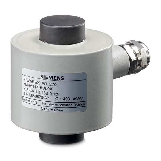
SIWAREX WL270
Pressure piece set
CP-S SB
Operating Instructions
11/2010
A5E03323543B
___________________
Introduction
Notes on handling the
___________________
product
___________________
Description
___________________
Application planning
___________________
Installation
___________________
Service and maintenance
___________________
Technical data
___________________
Dimension drawings
___________________
Ordering data
___________________
Appendix
1
2
3
4
5
6
7
8
9
A
Advertisement
Table of Contents

Related Manuals for Siemens SIWAREX WL270 CP-S SB


Summary of Contents for Siemens SIWAREX WL270 CP-S SB
- Page 1 ___________________ CP-S SB Introduction Notes on handling the ___________________ product ___________________ Description SIWAREX WL270 ___________________ Application planning Pressure piece set ___________________ CP-S SB Installation ___________________ Service and maintenance Operating Instructions ___________________ Technical data ___________________ Dimension drawings ___________________ Ordering data ___________________ Appendix 11/2010 A5E03323543B...
- Page 2 Note the following: WARNING Siemens products may only be used for the applications described in the catalog and in the relevant technical documentation. If products and components from other manufacturers are used, these must be recommended or approved by Siemens. Proper transport, storage, installation, assembly, commissioning, operation and maintenance are required to ensure that the products operate safely and without any problems.
-
Page 3: Table Of Contents
Table of contents Introduction..............................5 Purpose of this documentation ......................5 History ............................5 Scope of delivery ...........................5 Environmental protection .......................5 Notes on handling the product ........................7 Description..............................9 Application............................9 3.1.1 Use of the pressure piece set ......................9 3.1.2 Lifting protection...........................10 3.1.3 Overload protection........................10 3.1.4... - Page 4 Table of contents Technical data ............................31 Technical data..........................31 Dimension drawings ..........................33 Dimension drawing of the pressure piece set ................33 Dimension drawing of the grounding cable................. 33 Ordering data............................35 Ordering data ..........................35 Appendix..............................37 Technical support........................37 Index................................
-
Page 5: Introduction
Introduction Purpose of this documentation These instructions contain all the information you need for commissioning and using the device. It is aimed at persons who install the device mechanically and commission it, as well as at service and maintenance engineers. History The following versions of this documentation have been released to date. - Page 6 Introduction 1.4 Environmental protection CP-S SB Operating Instructions, 11/2010, A5E03323543B...
-
Page 7: Notes On Handling The Product
All obligations on the part of Siemens AG are contained in the respective sales contract, which also contains the complete and solely applicable liability provisions. The provisions defined in the sales contract for the responsibility for defects are neither extended nor limited by the remarks in this document. - Page 8 EC directive 94/9 EC (ATEX). Trademarks SIWAREX ® is a registered trademark of Siemens AG. All other names appearing in these instructions may be trademarks; use of such names by third parties for their own purposes may infringe upon owners rights.
-
Page 9: Description
● Has a self-centering effect on the load bearing implement Pressure piece set for SIWAREX WL270 CP-S SB The self-centering pressure piece set for SIWAREX WL270 CP-S SB load cells is especially well suited for installation in vehicle scales, platform weighing machines, and container weighers. -
Page 10: Lifting Protection
Therefore supporting structures complying with the general rules of mechanical engineering must be designed by the customer for installing the pressure piece set. As an alternative installation units from the product range of Siemens can be used. 3.1.2 Lifting protection The lifting protection prevents the load bearing implements from being lifted off of the load cells. -
Page 11: Use Of The Grounding Cable
Description 3.2 Layout and function 3.1.4 Use of the grounding cable The grounding cable is used to protect the load cells from undesired currents. The causes of such currents are, for example: ● Equalizing currents with missing or faulty equipotential bonding conductors. ●... - Page 12 Description 3.2 Layout and function ① Upper pressure piece ② Load cell, not included in the scope of delivery ③ Pin in lower pressure piece: Prevents the load cell from twisting ④ Lower twist-proof pressure piece Figure 3-3 Exploded view: Pressure piece set with installed load cell Principle of operation The pressure pieces ensure the lateral guidance of the load cells and, together with the load cell, form a self-centering unit.
-
Page 13: Design And Function Of The Grounding Cable
Description 3.2 Layout and function 3.2.2 Design and function of the grounding cable Design The grounding cable consists of a fine-gauge copper wire with a cross-section of 50 mm and two lugs, Ø 10 mm. Principle of operation The grounding cable represents an electrical bypass via the load cell and pressure piece set. High weld currents can destroy the load cell, pressure piece set or the electronics. - Page 14 Description 3.2 Layout and function CP-S SB Operating Instructions, 11/2010, A5E03323543B...
-
Page 15: Application Planning
Application planning Load cell dummies Principle of operation Load cells are sensitive sensors. To protect the load cells from becoming damaged during installation and transport, the load cells should only be installed at the last minute. During installation and transport, the load cells should therefore be replaced by space holders, so- called dummies or phantoms. -
Page 16: Load Pick-Up
Application planning 4.3 Load pick-up Load pick-up Mounting surfaces For the mounting surfaces of the pressure piece set, the following requirements apply: ● The positional and angular deviations of the mounting surfaces to each other should correspond to the general tolerances for welded constructions in EN ISO 13920. ●... -
Page 17: Overload Protection
Application planning 4.4 Overload protection Height compensation of the support points With this method, the output signals of all of the load cells are attuned to each other under a load. To ensure that all of the load cells receive approximately the same load, spacer plates are used to compensate the heights. - Page 18 Application planning 4.4 Overload protection Overload protection in the transverse direction For the CP-S SB load cells, the weight force is introduced into the load cells via spherical bearing surfaces. Up to a certain degree, these bearing surfaces allow lateral movement of the load bearing implement or a change in its length as a result of expansion due to heat.
-
Page 19: Guide Elements
Application planning 4.5 Guide elements Guide elements Use the guide elements in the following cases: ● A weight should be determined under the influence of transverse forces. ● Horizontal movement of the load bearing implement should be prevented. A change in the distance between the support points, for example as a result of expansion of the load bearing implement due to heat, must not lead to mutual tensioning of the guide elements. -
Page 20: Protection Against Explosion
Application planning 4.6 Protection against explosion To ensure that no force components occur in the measuring direction, you must install guide elements at precise right angles to the effective direction of the load cells. Three guide elements are sufficient to statically fix a weighing platform or container. NOTICE Weighing errors With four guide elements, there is a risk of the guide elements mutually tensioning, which in... -
Page 21: Installation
Installation Safety information/instructions Load cells are precision components and must therefore be handled carefully. Particular care must be taken during transport and installation. WARNING Danger to life from falling loads Load cells are not machine components which have been constructed with the normal safety factors. - Page 22 Installation 5.1 Safety information/instructions CAUTION Damage to load cells through high currents If welding is undertaken after the load cells have been installed, ensure that the welding current is not diverted through the load cells. – You can do this by attaching the grounding clamp of the welding unit making reliable contact close to the weld.
-
Page 23: Mounting The Pressure Piece Set
Installation 5.2 Mounting the pressure piece set Mounting the pressure piece set 5.2.1 General installation information The installation conditions vary widely. The dead load of the load bearing implement can be very low or relatively high. You might be dealing with a container, platform or a roller conveyor. -
Page 24: Preparing The Load Cell
Installation 5.2 Mounting the pressure piece set 5.2.3 Preparing the load cell CAUTION Damage to the load cell Observe the operating instructions for the load cell. When mounting the load cell, ensure that you do not damage or cut the cables of the load cell. -
Page 25: Preparing The Pressure Piece Set
Installation 5.2 Mounting the pressure piece set 5.2.4 Preparing the pressure piece set ① Upper pressure piece ② Lower pressure piece Figure 5-2 Scope of delivery 1. Unpack the pressure piece set. 2. Read the accompanying information sheet. 3. Check the delivered unit. See also Scope of delivery (Page 5) 5.2.5... - Page 26 Installation 5.2 Mounting the pressure piece set Compressive strength of the mounting surfaces The compressive strength of the mounting surfaces has to be appropriate for the surface pressure of the pressure pieces. Align the load cell The lower pressure piece features a pin. This prevents the load cell from twisting. You can align the lower pressure piece accordingly to determine the orientation of the cable terminal on the load cell.
-
Page 27: Checking The Installation
Installation 5.3 Installing the grounding cable Procedure Figure 5-3 Inserting the load cell 1. Grease the bearing surfaces of the load cell with a bearing lubricant. 2. Insert load cell with the pressure pieces. 3. Lower the load bearing implement onto the load cells. 5.2.6 Checking the installation CAUTION... -
Page 28: Dismantling
Installation 5.4 Dismantling Dismantling For the disassembly of load cells, the same safety rules and requirements apply as for installation and assembly. 1. Disconnect all the supply voltages and auxiliary voltages. 2. Secure the load carrier against falling. 3. Use appropriate hoisting gear and tools. 4. -
Page 29: Service And Maintenance
Service and maintenance Servicing and maintenance Important notes on cleaning CAUTION Damage to load cells, measurement errors Dirt must not be allowed to accumulate in the vicinity of a load cell. Do not subject cable glands, sealing elements and flat seals directly to the jet from a high-pressure hose. - Page 30 Service and maintenance 6.1 Servicing and maintenance Grounding cable ● Check the connecting points at regular intervals for corrosion and conductivity. CP-S SB Operating Instructions, 11/2010, A5E03323543B...
-
Page 31: Technical Data
Technical data Technical data Pressure piece set Variable Value For a rated load of 100 t Maximum lateral deflection with load cell ±8 mm Restoring force per millimeter of lateral deflection of the top plate 0.5% per mm in % of the applied load with load cell CP-S SB Operating Instructions, 11/2010, A5E03323543B... - Page 32 Technical data 7.1 Technical data CP-S SB Operating Instructions, 11/2010, A5E03323543B...
-
Page 33: Dimension Drawings
Dimension drawings Dimension drawing of the pressure piece set The following dimension drawing shows the SIWAREX WL270 CP-S SB pressure piece. All dimensions are in millimeters. Figure 8-1 Dimension drawing: Pressure piece CP-S SB Dimension drawing of the grounding cable... - Page 34 Dimension drawings 8.2 Dimension drawing of the grounding cable CP-S SB Operating Instructions, 11/2010, A5E03323543B...
-
Page 35: Ordering Data
Ordering data Ordering data Pressure piece set Pressure piece set Designation Rated load Order No. CP-S SB 100 t 7MH5710-6AD00 The load cells are not included. Grounding cable Highly flexible grounding cable Designation Description Order No. SIWAREX R grounding cable Highly flexible grounding cable for 7MH3701-1AA1 diverting parasitic currents... - Page 36 Ordering data 9.1 Ordering data CP-S SB Operating Instructions, 11/2010, A5E03323543B...
-
Page 37: Appendix
Service & Support on the Internet In addition to our documentation, we offer a comprehensive knowledge base online on the Internet at: Services & Support (http://www.siemens.com/automation/service&support) There you will find: ● The latest product information, FAQs, downloads, tips and tricks. - Page 38 Appendix A.1 Technical support Additional Support Please contact your local Siemens representative and offices if you have any questions about the products described in this manual and do not find the right answers. Find your contact partner at: Partner (http://www.automation.siemens.com/partner) A signpost to the documentation of the various products and systems is available at: Documentation (http://www.siemens.com/weighing/documentation)
-
Page 39: Index
Index Preparing the load cell, 24 Installing the load cell, 25 Internet, 37 Additional Support, 38 Application, 9 Lifting protection, 15 Application, 10 Load cell Preparing, 24 Cleaning, 29 Load cell dummy, 15 Customer Support Hotline, 37 Load pick-up, 16 Design Mounting surfaces, 16 Grounding cable, 13... - Page 40 Index Service, 37 Support, 38 Support point, 16 Technical data, 31 CP-S SB Operating Instructions, 11/2010, A5E03323543B...
Need help?
Do you have a question about the SIWAREX WL270 CP-S SB and is the answer not in the manual?
Questions and answers