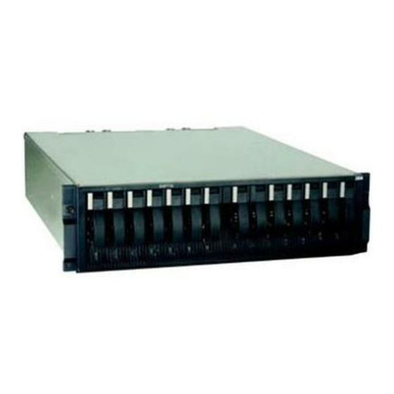
Page 14
3. Attach signal cables to connectors. 3. Remove signal cables from connectors. 4. Attach power cords to outlet. 4. Remove all cables from devices. 5. Turn device ON. IBM TotalStorage DS4000 EXP700 and EXP710 Storage Expansion Enclosures: Installation, User’s, and Maintenance Guide...
Page 15
Statement 3: CAUTION: When laser products (such as CD-ROMs, DVD drives, fiber optic devices, or transmitters) are installed, note the following: v Do not remove the covers. Removing the covers of the laser product could result in exposure to hazardous laser radiation. There are no serviceable parts inside the device.
Page 16
To remove all electrical current from the device, ensure that all power cords are disconnected from the power source. IBM TotalStorage DS4000 EXP700 and EXP710 Storage Expansion Enclosures: Installation, User’s, and Maintenance Guide...
Page 17
Statement 8: CAUTION: Never remove the cover on a power supply or any part that has the following label attached. Hazardous voltage, current, and energy levels are present inside any component that has this label attached. There are no serviceable parts inside these components.
Page 18
IBM TotalStorage DS4000 EXP700 and EXP710 Storage Expansion Enclosures: Installation, User’s, and Maintenance Guide...
Enclosures. It also provides hardware maintenance and troubleshooting information. FAStT product renaming IBM is in the process of renaming some FAStT family products. Table 1 identifies each new DS4000 product name with its corresponding FAStT product name. Note that this change of product name only indicates no change in functionality or warranty.
DS4000 EXP700 or DS4000 EXP710 storage expansion enclosure. Each caution and danger statement is numbered for easy reference to the corresponding statements in the safety document. xviii IBM TotalStorage DS4000 EXP700 and EXP710 Storage Expansion Enclosures: Installation, User’s, and Maintenance Guide...
The following types of notices and statements are used in this document: v Note: These notices provide important tips, guidance, or advice. v Important: These notices provide information or advice that might help you avoid inconvenient or problem situations. v Attention: These notices indicate possible damage to programs, devices, or data.
DS4500 storage server library Table 2 on page xxi associates each document in the DS4500 (previously FAStT900) storage server library with its related common user tasks. IBM TotalStorage DS4000 EXP700 and EXP710 Storage Expansion Enclosures: Installation, User’s, and Maintenance Guide...
Table 2. TotalStorage DS4500 Fibre Channel Storage Server document titles by user tasks Title User Tasks Planning Hardware Software Configuration Operation and Diagnosis and Installation Installation Administration Maintenance IBM TotalStorage DS4500 Installation and Support Guide, GC26-7727 IBM TotalStorage DS4500 Fibre Channel Cabling Instructions, GC26-7729 IBM TotalStorage DS4500 Storage Server User’s Guide, GC26-7726...
IBM DS4400 Fibre Channel Storage Server User’s Guide, GC26-7730 IBM DS4400 Fibre Channel Storage Server Installation and Support Guide, GC26-7731 IBM DS4400 Fibre Channel Cabling Instructions, GC26-7732 xxii IBM TotalStorage DS4000 EXP700 and EXP710 Storage Expansion Enclosures: Installation, User’s, and Maintenance Guide...
Table 4. TotalStorage DS4300 Fibre Channel Storage Server document titles by user tasks Title User Tasks Planning Hardware Software Configuration Operation and Diagnosis and Installation Installation Administration Maintenance IBM TotalStorage DS4300 Fibre Channel Storage Server Installation and User’s Guide, GC26-7722 IBM TotalStorage DS4300 Rack Mounting Instructions, GC26-7724 IBM TotalStorage DS4300 Fibre...
Software Configuration Operation and Diagnosis and Installation Installation Administration Maintenance IBM TotalStorage DS4100 Installation, User’s and Maintenance Guide, GC26-7733 IBM TotalStorage DS4100 Cabling Guide, 24P8973 xxiv IBM TotalStorage DS4000 EXP700 and EXP710 Storage Expansion Enclosures: Installation, User’s, and Maintenance Guide...
Title User tasks Planning Hardware Software Configuration Operation and Diagnosis and installation installation administration maintenance IBM TotalStorage DS4000 Storage Manager Version 9 Installation and Support Guide for Windows 2000/Server 2003, NetWare, ESX Server, and Linux, GC26-7706 IBM TotalStorage DS4000 Storage...
DS4000 Fibre Channel and Serial ATA Intermix Premium Feature Installation Overview GC26-7713 Fibre Channel Solutions - IBM DS4000 FAStT EXP500 Installation and User’s Guide, 59p5637 xxvi IBM TotalStorage DS4000 EXP700 and EXP710 Storage Expansion Enclosures: Installation, User’s, and Maintenance Guide...
If you need help, service, or technical assistance or just want more information about IBM products, you will find a wide variety of sources available from IBM to assist you. This section contains information about where to go for additional...
Web sites IBM maintains pages on the World Wide Web where you can get the latest technical information and download device drivers and updates. v For DS4000 information, go to the following Web site: www.ibm.com/servers/storage/support/disk/...
For information about which products are supported by Support Line in your country or region, go to the following Web site: www.ibm.com/services/sl/products/ For more information about the IBM Support Line and other IBM services, go to the following Web sites: v www.ibm.com/services/ v www.ibm.com/planetwide/...
Page 32
IBM TotalStorage DS4000 EXP700 and EXP710 Storage Expansion Enclosures: Installation, User’s, and Maintenance Guide...
DS4000 EXP700 and DS4000 EXP710, the generic term storage expansion enclosure is used. Overview The IBM TotalStorage DS4000 EXP700 (Machine Type 1740, Models 1RU and 1RX) and DS4000 EXP710 (Machine Type 1740, Model 710) storage expansion enclosures provide high-capacity, fibre channel disk storage. Both storage expansion enclosures deliver fast, high-volume data transfer, retrieval, and storage functions for multiple drives, to multiple hosts.
ESM firmware requirement for intermixing DS4000 EXP700s or DS4000 EXP710s is version 9326. For more information, see “Intermixing DS4000 EXP700s and DS4000 EXP710s in the same loop” on page 44. IBM TotalStorage DS4000 EXP700 and EXP710 Storage Expansion Enclosures: Installation, User’s, and Maintenance Guide...
Download the latest version of the DS4000 Storage Manager host software and the any appropriate DS4000 product series firmware at the time of the initial installation and when product updates become available. To be notified of important product updates, you must first register at the IBM Support and Download Web site: www.ibm.com/support/us/ Go to the Personalized Support section of the web page and click My support.
IBM Small Form-Factor Pluggable (SFP) module v IBM LC-LC Fibre Channel cable For DS4000 EXP700 only: Depending on your configuration, you might also need the following options: IBM TotalStorage DS4000 EXP700 and EXP710 Storage Expansion Enclosures: Installation, User’s, and Maintenance Guide...
IBM LC-SC Fibre Channel Cable Adapter v Gigabit Interface Converter (GBIC) Note: For some storage expansion enclosure models, you must order these options separately. Storage expansion enclosure components The storage expansion enclosure has the following removable components, called customer replaceable units (CRUs). All CRUs are accessible from the front or back of the storage expansion enclosure.
ESMs, which are located in the ESM bays. The ESMs monitor the overall status of the storage expansion enclosure. The DS4000 EXP700 ESMs provide a 1 IBM TotalStorage DS4000 EXP700 and EXP710 Storage Expansion Enclosures: Installation, User’s, and Maintenance Guide...
Gb/s or 2 Gb/s fibre channel interface to the DS4000 storage server drive loop ports. The DS4000 EXP710 provides a 2 Gb/s fibre channel interface only to the DS4000 storage server drive loop ports. Attention: After you remove an ESM, wait 70 seconds before reseating or replacing the ESM.
The storage expansion enclosure requires that both power supplies be installed to meet Electromagnetic Compatibility (EMC) and cooling requirements. Figure 5 on page 9 shows their locations. IBM TotalStorage DS4000 EXP700 and EXP710 Storage Expansion Enclosures: Installation, User’s, and Maintenance Guide...
Levers Power LEDs Fault LEDs Power switches 1 Gb/s 2 Gb/s Conflict Tray Number AC power connectors Power supply CRUs Figure 5. Power-supply controls, indicators, and connectors v Levers: When you remove or install a power supply CRU, the levers located at the top of the power supply CRU must be unlocked.
ESM latch Enclosure ID Enclosure ID switch tens switch ones 1Gb/s/2Gb/s place (X10) place (X1) Switch cover switch plate Figure 7. ESMs and user controls (DS4000 EXP700) IBM TotalStorage DS4000 EXP700 and EXP710 Storage Expansion Enclosures: Installation, User’s, and Maintenance Guide...
Page 43
The ESM LED positions are changed slightly in the EXP710, as shown in Figure 8. Power LED Fault LED Over-temperature LED Input bypass LED Output bypass LED Figure 8. ESM LEDs on the DS4000 EXP710 v SFP module input/output ports: Each ESM has two SFP module connector ports for connecting your storage expansion enclosure to the controller or connecting two or more storage expansion enclosures together.
Channel Storage Server TotalStorage DS4500 Fibre Storage Manager 9.1 or later 6.10.xx.xx or later 2 Gb/s Channel Storage Server DS4000 EXP700 Storage 2 Gb/s Expansion Enclosure IBM TotalStorage DS4000 EXP700 and EXP710 Storage Expansion Enclosures: Installation, User’s, and Maintenance Guide...
Note: For the latest information about supported servers and operating systems for ® the DS4000 EXP700 and DS4000 EXP710, go to the ServerProven site at www.ibm.com/pc/us/compat/ Storage expansion enclosure operating specifications This section provides general information about the storage expansion enclosure. All components plug directly into the backplane.
Where racks are in rows front-to-front or back-to-back, a gap of at least 1220 mm (48 in.) must separate the rows across the cold aisle. IBM TotalStorage DS4000 EXP700 and EXP710 Storage Expansion Enclosures: Installation, User’s, and Maintenance Guide...
Page 47
v To ensure correct airflow in each rack, the rack filler plates must be installed in unused positions. Also, all the gaps in the front of the racks must be sealed, including the gaps between the storage expansion enclosures. back T42 racks front Perforated tiles...
Page 48
IBM TotalStorage DS4000 EXP700 and EXP710 Storage Expansion Enclosures: Installation, User’s, and Maintenance Guide...
3. Remove the storage expansion enclosure from its shipping container and check the contents (see “Inventory checklist” on page 4). If any items are missing, contact your IBM reseller before proceeding. 4. Assemble the tools and equipment you will need for installation. These might...
To prepare the rack for installation, review the following list and complete all applicable preparatory procedures: 1. Move, unpack, and level the rack at the installation site. 2. Remove the external rack panels. IBM TotalStorage DS4000 EXP700 and EXP710 Storage Expansion Enclosures: Installation, User’s, and Maintenance Guide...
3. Stop all I/O activity to the devices in the rack (optional). 4. Turn off all storage expansion enclosure and rack power, and disconnecting existing power, network, and other external cables (optional). 5. Install additional interface cables and power cables. 6.
ESM from the bay as shown in Figure 10. EMS latch Lever Pull ring Figure 10. Removing an ESM 3. Place the ESM on a level surface. IBM TotalStorage DS4000 EXP700 and EXP710 Storage Expansion Enclosures: Installation, User’s, and Maintenance Guide...
Complete the following steps to remove a power supply CRU: 1. Grasp the pull-ring on the power-supply lever and squeeze the latch to release 2. Pull the lever open and remove the power supply as shown in Figure 11. Lever Pull ring Figure 11.
This rack cabinet conforms to the Electronic Industries Association (EIA) standard. Where you place the support rails in the cabinet depends on where you intend to position the storage expansion enclosure. IBM TotalStorage DS4000 EXP700 and EXP710 Storage Expansion Enclosures: Installation, User’s, and Maintenance Guide...
Page 55
Use the following templates (Figure 14 on page 24 and Figure 15 on page 25) to identify the proper locations for inserting M6 screws when mounting the support rails and storage expansion enclosure to a rack. The locations for the M6 screws are highlighted in the templates.
Page 56
Bezel assembly Bezel assembly ront Right ront Left Rail assembly Rail assembly ront Right ront Left ® Printed in the U.S.A. Figure 14. Front rack mounting template IBM TotalStorage DS4000 EXP700 and EXP710 Storage Expansion Enclosures: Installation, User’s, and Maintenance Guide...
REAR Rack Mounting Template Rail assembly Rail assembly (Rear Right) (Rear Left Figure 15. Rear rack mounting template Chapter 2. Installing and cabling the storage expansion enclosure...
Page 58
(1) from the bezel. Align the bezel locator pins; then, secure the bezel with two black hex screws (2). Secure the rear of the device with two small IBM TotalStorage DS4000 EXP700 and EXP710 Storage Expansion Enclosures: Installation, User’s, and Maintenance Guide...
screws (3) (removed in step 2). After you install the storage expansion enclosure in a rack cabinet, continue with “Replacing the CRUs.” Replacing the CRUs Complete the following steps to replace the ESM CRUs that you removed: 1. Slide one ESM into the empty slot in the storage expansion enclosure. Be sure the levers are pulled straight out as you slide it in, as shown in Figure 16.
Page 60
4. Repeat steps 1 through 3 to replace the second fan. IBM TotalStorage DS4000 EXP700 and EXP710 Storage Expansion Enclosures: Installation, User’s, and Maintenance Guide...
Complete the following steps to replace the hot-swap hard disk drives that you removed: 1. Lift up on the handle and gently push the drive CRU into the empty bay until the tray handle touches the storage expansion enclosure bezel. 2.
ID setting to a value other than 00. Each server unit should have a unique ID if it is going IBM TotalStorage DS4000 EXP700 and EXP710 Storage Expansion Enclosures: Installation, User’s, and Maintenance Guide...
You then use dual fiber-optic cables to connect one storage expansion enclosure to another. v Fibre channel cable restrictions: RAID controllers use specific IBM fibre channel options. Refer to the Fibre Channel Cabling Instructions that come with your storage server for the cable option that is required for your configuration.
SFP module from the port. Refer to “Removing SFP modules” on page 34 for more information. Complete the following steps to install an SFP module: Statement 3: IBM TotalStorage DS4000 EXP700 and EXP710 Storage Expansion Enclosures: Installation, User’s, and Maintenance Guide...
CAUTION: When laser products (such as CD-ROMs, DVD drives, fiber optic devices, or transmitters) are installed, note the following: v Do not remove the covers. Removing the covers of the laser product could result in exposure to hazardous laser radiation. There are no serviceable parts inside the device.
For SFP modules that contain wire tabs, unlock the SFP module latch by pulling the wire latch outward 90°, as shown in Figure 24 on page 35. IBM TotalStorage DS4000 EXP700 and EXP710 Storage Expansion Enclosures: Installation, User’s, and Maintenance Guide...
Wire Protective module Figure 24. Unlocking the SFP module latch - wire variety 3. With the SFP latch in the unlocked position, slide the SFP module out of the port. 4. Replace the protective cap on the SFP module. 5. Place the SFP module into a static-protective package. Handling fiber-optic cables Before using fiber-optic cables, read the following precautions.
39. Connecting an LC-LC cable to an SFP module Complete the following steps to connect an LC-LC fibre channel cable to an SFP module: IBM TotalStorage DS4000 EXP700 and EXP710 Storage Expansion Enclosures: Installation, User’s, and Maintenance Guide...
Page 69
Statement 3: CAUTION: When laser products (such as CD-ROMs, DVD drives, fiber optic devices, or transmitters) are installed, note the following: v Do not remove the covers. Removing the covers of the laser product could result in exposure to hazardous laser radiation. There are no serviceable parts inside the device.
Figure 28. LC-LC fibre channel cable lever and latches 2. Carefully pull on the connector to remove the cable from the SFP module as shown in Figure 29 on page 39. IBM TotalStorage DS4000 EXP700 and EXP710 Storage Expansion Enclosures: Installation, User’s, and Maintenance Guide...
LC connector into one of the following devices that require SC connectors: v IBM FAStT200 Storage Server v IBM FAStT EXP500 Storage Expansion Enclosure v IBM FAStT500 RAID Controller Enclosure Unit Note: The LC-SC fibre channel cable adapter is required only in some configurations with the DS4000 EXP700.
3. Remove the two protective caps from the LC connector end of the LC-SC cable adapter as shown in Figure 31. Save the protective caps for future use. Figure 31. Removing the LC-SC cable adapter protective caps IBM TotalStorage DS4000 EXP700 and EXP710 Storage Expansion Enclosures: Installation, User’s, and Maintenance Guide...
4. Carefully insert the other end of the LC-LC cable into the LC connector end of the LC-SC cable adapter as shown in Figure 32. Push in the connector until it clicks into place. Figure 32. Connecting an LC-LC cable into the LC-SC cable adapter 5.
Requirements for connecting DS4000 EXP700s or DS4000 EXP710s with DS4000 EXP100s in the same loop. See “Intermixing DS4000 EXP700s or DS4000 EXP710s with DS4000 EXP100s in the same loop” on page 52. IBM TotalStorage DS4000 EXP700 and EXP710 Storage Expansion Enclosures: Installation, User’s, and Maintenance Guide...
Storage Server, DS4400 Fibre Channel Storage Server, or DS4500 Fibre Channel Storage Server. Note: Connections to other storage servers might be supported in the future. Check the IBM DS4000 storage support Web site Chapter 2. Installing and cabling the storage expansion enclosure...
EXP710s and EXP700s is version 9326. Verify that the ESM firmware for all DS4000 EXP700s is at version 9326 or higher before intermixing DS4000 EXP700s with DS4000 EXP710s. IBM TotalStorage DS4000 EXP700 and EXP710 Storage Expansion Enclosures: Installation, User’s, and Maintenance Guide...
Page 77
“Upgrading ESMs with the DS4000 EXP700 Models 1RU/1RX Switched-ESM Option Upgrade Kit,” on page 85. Important IBM does not support drive loop configurations in which all DS4000 EXP710s are not grouped together. Figure 35 on page 46 though Figure 37 on page 48 show three acceptable DS4000 EXP700 and DS4000 EXP710 intermixing cabling configurations in which all DS4000 EXP710s are grouped together.
In Figure 38 on page 49 and Figure 39 on page 50, the intermixed configurations shown are unacceptable because the DS4000 EXP710s in the redundant drive loop are not grouped together. IBM TotalStorage DS4000 EXP700 and EXP710 Storage Expansion Enclosures: Installation, User’s, and Maintenance Guide...
(because the storage server does not support mixed drive loop speeds). If you are intermixing FAStT EXP500s and DS4000 EXP700s, it is strongly recommended that you do not cable the FAStT EXP500 and DS4000 EXP700 IBM TotalStorage DS4000 EXP700 and EXP710 Storage Expansion Enclosures: Installation, User’s, and Maintenance Guide...
The maximum Fibre Channel transfer speed in all of the DS4000 EXP700s must be set to 1 Gbps because the maximum FC transfer speed of the IBM FAStT EXP500 storage expansion enclosures is 1 Gbps. Otherwise, a drive channel mini hub data rate mismatch error will be generated.
ESM firmware for all DS4000 EXP100s is at version 9554 or higher. You must also verify that the ESM firmware for all DS4000 EXP710s and EXP700s is at version 9326 or higher. IBM TotalStorage DS4000 EXP700 and EXP710 Storage Expansion Enclosures: Installation, User’s, and Maintenance Guide...
RAID controllers Figure 40. Redundant loop configuration IBM fibre channel disk drives are dual-ported, providing individual access from two fibre channel loops to the same disk drive. When configuring the ESMs, configure the second ESM the same way you configured the first ESM. Refer to the Fibre Channel Cabling Instructions that come with your storage server for more information about dual-loop support and implementation.
5. Make a fibre-channel connection from the DS4000 storage server drive port to the IN port in the right ESM of the last storage expansion enclosure in the redundant drive loop (connection 6). IBM TotalStorage DS4000 EXP700 and EXP710 Storage Expansion Enclosures: Installation, User’s, and Maintenance Guide...
Cabling the storage expansion enclosures to the storage server The following sections describe the procedure for connecting a single storage expansion enclosure or a storage expansion enclosure loop to the storage server: IBM TotalStorage DS4000 EXP700 and EXP710 Storage Expansion Enclosures: Installation, User’s, and Maintenance Guide...
v “Cabling the storage expansion enclosure to a FAStT200 or DS4300 Storage Server” v “Cabling the EXP700 to a FAStT500 RAID Controller Enclosure Unit” on page 58 v “Cabling the storage expansion enclosure to a DS4400 or DS4500” on page 60 Cabling the storage expansion enclosure to a FAStT200 or DS4300 Storage Server Complete the following steps to cable the storage expansion enclosure to a...
FAStT500 instructions apply only to connections with the DS4000 EXP700. 1. Insert a GBIC into a drive mini-hub port located on the back of a FAStT500, as shown in Figure 47 on page 59. IBM TotalStorage DS4000 EXP700 and EXP710 Storage Expansion Enclosures: Installation, User’s, and Maintenance Guide...
GBIC Figure 47. Installing a GBIC in a FAStT500 2. Using Figure 48 on page 60 as a guide, complete the following steps to connect the DS4000 EXP700 to a FAStT500 RAID controller: a. Connect the SC end of an LC-SC cable adapter to the GBIC. b.
1. Install an SFP module in the drive mini-hub port on the back of a DS4400 or DS4500 Fibre Channel Storage Server. 2. Connect an LC-LC fiber-optic cable into the SFP module, as shown in Figure 49 on page 61. IBM TotalStorage DS4000 EXP700 and EXP710 Storage Expansion Enclosures: Installation, User’s, and Maintenance Guide...
Mini hub DS4400 or DS4500 b /s b /s b /s b /s b /s b /s b /s b /s b /s b /s b /s b /s b /s b /s b /s b /s LC-LC cable Drive mini-hub SFP module ports Figure 49.
Page 94
Note: Figure 51 on page 63 shows only one example of redundant loop cabling. Other examples are provided in “Cabling the storage expansion enclosures in a redundant loop” on page 53. IBM TotalStorage DS4000 EXP700 and EXP710 Storage Expansion Enclosures: Installation, User’s, and Maintenance Guide...
Figure 51. Cabling a new storage expansion enclosure to a redundant loop For more detail on the process of adding a new storage expansion enclosure to an existing loop, refer to the IBM TotalStorage DS4000 Fibre Channel Hard Drive and Storage Expansion Enclosure Installation and Migration Guide.
An IBM technical-support representative instructs you to turn off the power. v A power outage or emergency situation occurs, see “Restoring power after an emergency” on page 65. IBM TotalStorage DS4000 EXP700 and EXP710 Storage Expansion Enclosures: Installation, User’s, and Maintenance Guide...
Statement 5: CAUTION: The power control button on the device and the power switch on the power supply do not turn off the electrical current supplied to the device. The device also might have more than one power cord. To remove all electrical current from the device, ensure that all power cords are disconnected from the power source.
Page 98
The green LEDs on the front and the back of the storage expansion enclosure should remain lit. If other amber Fault LEDs are lit, see Chapter 4, “Hardware maintenance,” on page 77. IBM TotalStorage DS4000 EXP700 and EXP710 Storage Expansion Enclosures: Installation, User’s, and Maintenance Guide...
Save the empty trays for future use. Each of the 14 bays must always contain either a blank tray or a hot-swap hard disk drive. v Drive CRUs: Your storage expansion enclosure supports IBM 2 Gb/s fibre channel hard disk drives.
Release the blue latch on the drive CRU by pressing on the inside of the bottom of the tray handle. IBM TotalStorage DS4000 EXP700 and EXP710 Storage Expansion Enclosures: Installation, User’s, and Maintenance Guide...
b. Pull the handle on the tray out so that it is in the open position, as shown in Figure 53. Tray handle Blue latch Figure 53. Drive CRU latch c. Slide the drive CRU into the empty bay until the tray handle touches the storage expansion enclosure bezel.
25R0166) and are upgrading your DS4000 EXP700 with ESMs that have the same internal switched capabilities as the DS4000 EXP710, see Appendix B, “Upgrading ESMs with the DS4000 EXP700 Models 1RU/1RX Switched-ESM Option Upgrade Kit,” on page 85. IBM TotalStorage DS4000 EXP700 and EXP710 Storage Expansion Enclosures: Installation, User’s, and Maintenance Guide...
Page 103
Complete the following steps to remove and replace a failed ESM: 1. Check the storage-management software online help for instructions on ESM failure-recovery procedures. Follow the steps provided before continuing to step 2. 2. Label each cable to ensure that all cables are properly connected to the new ESM.
If it is not, remove the lever screw, flip the lever over, and tighten the screw on the opposite side as shown in Figure 56 on page 73. IBM TotalStorage DS4000 EXP700 and EXP710 Storage Expansion Enclosures: Installation, User’s, and Maintenance Guide...
Page 105
Lever screws Lever Pull ring Figure 56. Moving the power-supply lever and replacing the failed hot-swap power supply Complete the following steps to replace the failed hot-swap power supply. Statement 8: CAUTION: Never remove the cover on a power supply or any part that has the following label attached.
Use the handle (black knob) to pull the fan from the fan bay as shown in Figure 58 on page 75. IBM TotalStorage DS4000 EXP700 and EXP710 Storage Expansion Enclosures: Installation, User’s, and Maintenance Guide...
Page 107
T r a n fl ic t Figure 58. Replacing a hot-swap cooling fan 3. Install the new fan unit: a. Place the fan CRU in front of the fan bay. b. Ensure that you move the fan latch towards the exterior of the storage expansion enclosure (away from the power supply and ESM CRUs) before you insert the fan.
Page 108
IBM TotalStorage DS4000 EXP700 and EXP710 Storage Expansion Enclosures: Installation, User’s, and Maintenance Guide...
For instructions on how to obtain service and technical assistance for your storage server and other IBM products, see “Getting information, help, and service” on page xxvii. Note: See the IBM TotalStorage DS4000 Problem Determination Guide for additional troubleshooting and debugging procedures.
Reseat or replace power supply. Replace the power cord. Amber and green Power-supply Power-supply failure Replace the failed power-supply LEDs are lit CRU. IBM TotalStorage DS4000 EXP700 and EXP710 Storage Expansion Enclosures: Installation, User’s, and Maintenance Guide...
Page 111
Front panel Power-supply Make sure that the power cables problem are plugged in and that the power supplies are turned on. Hardware failure If any other LEDs are lit, replace the midplane. Contact an IBM technical-support representative. Chapter 4. Hardware maintenance...
Parts listing Figure 59 on page 81 and the following tables provide parts listings for the DS4000 EXP700 and DS4000 EXP710. IBM TotalStorage DS4000 EXP700 and EXP710 Storage Expansion Enclosures: Installation, User’s, and Maintenance Guide...
2.8M 36L8886 power cord 6952300 Appendix D, “Power cords,” on page 101 lists the required power cords for the storage expansion enclosure by country and region. IBM TotalStorage DS4000 EXP700 and EXP710 Storage Expansion Enclosures: Installation, User’s, and Maintenance Guide...
Accurate, up-to-date records make it easier to add other options and provide needed data whenever you contact technical support. Identification numbers Record and retain the following information. Product name: IBM TotalStorage DS4000 EXP700 Storage Expansion Enclosure Machine type: 1740 Model number:...
Page 116
Table 20. Hard disk drive record (continued) Replaced hard disk drive serial Bay Number Hard disk drive serial number number IBM TotalStorage DS4000 EXP700 and EXP710 Storage Expansion Enclosures: Installation, User’s, and Maintenance Guide...
Use the Recovery Guru function in the Storage Manager client Subsystem Management window for information on how to fix any non-optimal conditions. IBM TotalStorage DS4000 EXP700 and EXP710 Storage Expansion Enclosures: Installation, User’s, and Maintenance Guide...
Page 119
Recovery Guru function in the Storage Manager client Subsystem Management window for information on how to fix any non-optimal conditions. If you experience any of the following drive failure conditions, call IBM support for help: v The Empty Drive Slot icon ( ) displayed for drive slots that contain drives.
4. Upgrade the controller firmware to version 6.10.xx.xx or later. Attention: No I/O activity can be present during the firmware upgrade from version 5.4x.xx.xx or earlier to version 6.10.xx.xx or later. IBM TotalStorage DS4000 EXP700 and EXP710 Storage Expansion Enclosures: Installation, User’s, and Maintenance Guide...
Page 121
If there are excessive errors counts (in the tens or hundreds), do not perform the ESM upgrade until you have first resolved the errors using the drive path diagnostics described in the IBM TotalStorage DS4000 Problem Determination Guide. Attention: Resolve any non-optimal conditions before continuing with the next step.
Page 122
8. After you have upgraded and reconnected each ESM in the drive loop, reconnect the fibre channel cable from the controller drive port to the first IBM TotalStorage DS4000 EXP700 and EXP710 Storage Expansion Enclosures: Installation, User’s, and Maintenance Guide...
Page 123
Perform the fibre channel connection path diagnostic tests detailed in the IBM TotalStorage DS4000 Problem Determination Guide. v If neither of the above procedures resolves the issue, contact IBM technical support. 10. Use Storage Manager to verify that no ESM Redundancy Lost errors are being reported.
Page 124
DS4000 EXP700 1740 ESMs (FRU 19K1287) to IBM. Refer to the separate instructions included with the upgrade kit for return processing information for the DS4000 EXP700 ESMs you are replacing. IBM TotalStorage DS4000 EXP700 and EXP710 Storage Expansion Enclosures: Installation, User’s, and Maintenance Guide...
B” on page 98 v “Completing the firmware upgrade procedure” on page 98 Note: Refer to the IBM TotalStorage DS4000 Storage Manager Version 9 Installation and Support Guide for your operating system for more information on this upgrade procedure and any system requirements.
7. Add the TCP/IP address for Controller B to the Enterprise Management window of the DS4000 Storage Manager 9 client program. a. In the Enterprise Management Window, click Edit → Add Device. IBM TotalStorage DS4000 EXP700 and EXP710 Storage Expansion Enclosures: Installation, User’s, and Maintenance Guide...
b. The Add Device window opens. Enter the TCP/IP address of Controller B in the Host name or IP address field and click Add to add the DS4000 storage server in the DS4000 Storage Manger Client management domain. c. Click Close to close the Add Device window. Note: If this is an upgrade from an existing DS4000 storage server with version 5.4x.xx.xx firmware or earlier and there is an entry for this DS4000 storage server in the DS4000 Storage Manger Client Enterprise...
Page 128
Note: Do not re-insert Controller A to the DS4000 Storage Server yet. When you are done, continue to “Powering up the DS4000 Storage Server with DS4000 EXP710s attached” on page 97. IBM TotalStorage DS4000 EXP700 and EXP710 Storage Expansion Enclosures: Installation, User’s, and Maintenance Guide...
Powering up the DS4000 Storage Server with DS4000 EXP710s attached Perform the following steps to power up the DS4000 Storage Server with controller B only inserted and attached to the DS4000 EXP710 storage expansion enclosures. 1. Verify that the DS4000 EXP710 is correctly cabled to the DS4000 controller. For more information on cabling the DS4000 EXP710, see “Cabling the storage expansion enclosure”...
IBM TotalStorage DS4000 Storage Manager Concepts Guide for more information on how to download the storage expansion enclosure ESM firmware and drive firmware. IBM TotalStorage DS4000 EXP700 and EXP710 Storage Expansion Enclosures: Installation, User’s, and Maintenance Guide...
Page 131
2. Remove Controller A from the storage server chassis, wait a minute or so, and repeat step 2 on page 98. If the problem persists, call your IBM technical support representative. Appendix C. Upgrading the controller firmware for DS4300, DS4400, and DS4500 (DS4000 EXP710 only)
Page 132
IBM TotalStorage DS4000 EXP700 and EXP710 Storage Expansion Enclosures: Installation, User’s, and Maintenance Guide...
Appendix D. Power cords For your safety, IBM provides a power cord with a grounded attachment plug to use with this IBM product. To avoid electrical shock, always use the power cord and plug with a properly grounded outlet. IBM power cords used in the United States and Canada are listed by Underwriter’s Laboratories (UL) and certified by the Canadian Standards Association (CSA).
Page 134
Guatemala, Haiti, Honduras, Jamaica, Mexico, Micronesia 6952301 125V/10A (Federal States of), Netherlands Antilles, Nicaragua, 1.8M Panama, Peru, Philippines, Saudi Arabia, Taiwan, Thailand, Turks and Caicos Islands, United States, Venezuela IBM TotalStorage DS4000 EXP700 and EXP710 Storage Expansion Enclosures: Installation, User’s, and Maintenance Guide...
Page 136
Left arrow Move keyboard focus to the left. Right arrow Move keyboard focus to the right. Up arrow Move keyboard focus up one item in the list. IBM TotalStorage DS4000 EXP700 and EXP710 Storage Expansion Enclosures: Installation, User’s, and Maintenance Guide...
Web sites. The materials at those Web sites are not part of the materials for this IBM product, and use of those Web sites is at your own risk. IBM may use or distribute any of the information you supply in any way it believes appropriate without incurring any obligation to you.
IBM makes no representations or warranties with respect to non-IBM products. Support (if any) for the non-IBM products is provided by the third party, not IBM. Some software may differ from its retail version (if available), and may not include user manuals or all program functionality.
Properly shielded and grounded cables and connectors must be used in order to meet FCC emission limits. IBM is not responsible for any radio or television interference caused by using other than recommended cables and connectors or by unauthorized changes or modifications to this equipment.
Taiwanese Class A warning statement Japanese Voluntary Control Council for Interference (VCCI) statement IBM TotalStorage DS4000 EXP700 and EXP710 Storage Expansion Enclosures: Installation, User’s, and Maintenance Guide...
TotalStorage DS4000 publications. advanced technology (AT) bus architecture. A bus standard for IBM compatibles. It extends the XT bus If you do not find the term you are looking for, see architecture to 16 bits and also allows for bus...
Page 142
SCSI targets logically connected to an FC adapter. CRT. See cathode ray tube. DRAM. See dynamic random access memory. CRU. See customer replaceable unit. IBM TotalStorage DS4000 EXP700 and EXP710 Storage Expansion Enclosures: Installation, User’s, and Maintenance Guide...
Page 143
(CRU). Extended Industry Standard Architecture (EISA). A FlashCopy. A premium feature for DS4000 that can bus standard for IBM compatibles that extends the make an instantaneous copy of the data in a volume. Industry Standard Architecture (ISA) bus architecture to 32 bits and allows more than one central processing F_port.
Page 144
An entity in the storage partition topology and the physical network. that defines a logical collection of host computers that require shared access to one or more logical drives. IBM TotalStorage DS4000 EXP700 and EXP710 Storage Expansion Enclosures: Installation, User’s, and Maintenance Guide...
Page 145
Internet Protocol (IP) address. The unique 32-bit loop address. The unique ID of a node in address that specifies the location of each device or fibre-channel loop topology sometimes referred to as a workstation on the Internet. For example, 9.67.97.103 is loop ID.
Page 146
ASCII stanza files that are edited as part of configuring a drive into the kernel. IBM TotalStorage DS4000 EXP700 and EXP710 Storage Expansion Enclosures: Installation, User’s, and Maintenance Guide...
Page 147
(PTF). A temporary solution or bypass of a problem diagnosed by IBM in a current RVSD. See recoverable virtual shared disk. unaltered release of the program.
Page 148
(SAN). A dedicated storage synchronous write mode. In remote mirroring, an network tailored to a specific environment, combining option that requires the primary controller to wait for the IBM TotalStorage DS4000 EXP700 and EXP710 Storage Expansion Enclosures: Installation, User’s, and Maintenance Guide...
Page 149
acknowledgment of a write operation from the uninterruptible power supply. A source of power secondary controller before returning a write I/O request from a battery that is installed between a computer completion to the host. See also asynchronous write system and its power source. The uninterruptible power mode, remote mirroring, Metro Mirroring.
Page 150
IBM TotalStorage DS4000 EXP700 and EXP710 Storage Expansion Enclosures: Installation, User’s, and Maintenance Guide...
IBM DS4000 EXP700 35 when configured with a TotalStorage DS4300 Fibre an IBM DS4000 EXP710 35 Channel Storage Server 12 an IBM DS4000 storage server 35 when configured with a TotalStorage DS4500 Fibre device overview 43 Channel Storage Server 12...
Page 152
(ESM) 14 fan units 14 power supplies 14 fiber-optic cable IBM TotalStorage DS4000 EXP700 handling 35 adding to an existing fibre channel loop 61 cabling 42 IBM TotalStorage DS4000 EXP700 and EXP710 Storage Expansion Enclosures: Installation, User’s, and Maintenance Guide...
Page 153
IBM TotalStorage DS4000 EXP700 (continued) IBM TotalStorage DS4000 EXP710 (continued) cabling in a redundant loop 53 connectivity matrix 44 cabling to a DS4300 57 drive fault LED 8 cabling to a DS4400 60 enclosure ID switches 11 cabling to a DS4500 60...
Page 154
NetWare xix SM installation and support guide for Windows online help xix 2000 xix over-temperature LED 11 SM installation and support guide for Windows NT xix IBM TotalStorage DS4000 EXP700 and EXP710 Storage Expansion Enclosures: Installation, User’s, and Maintenance Guide...
Page 155
small form-factor pluggable module (SFP) connecting to an LC-LC fibre channel cable 36 description 11 important information about 32 location 11 port location, DS4000 EXP700 57 port location, DS4400 60 protective cap 33 removing an LC-LC cable 34, 38 static-protective package 33 unlocking the 34 software installation process xix software service and support xxviii...
Page 156
IBM TotalStorage DS4000 EXP700 and EXP710 Storage Expansion Enclosures: Installation, User’s, and Maintenance Guide...
Page 158
Part Number: 25R0398 Printed in USA gc26-7735-00...