
Related Manuals for Advantech PPC-112W


Summary of Contents for Advantech PPC-112W
- Page 1 User Manual PPC-112W/115W 11.6”/15.6” All-in-One Panel PC with Rockchip RK3399 Processor...
- Page 2 No part of this manual may be reproduced, copied, translated, or transmitted in any form or by any means without the prior written permission of Advantech Co., Ltd. The information provided in this manual is intended to be accurate and reliable.
- Page 3 This product has passed the CE test for environmental specifications when shielded cables are used for external wiring. We recommend the use of shielded cables. This type of cable is available from Advantech. Please contact your local supplier for ordering information.
- Page 4 N’ouvrez jamais l’appareil. Pour des raisons de sécurité, l’appareil ne doit être ouvert que par un technicien qualifié. If one of the following occurs, have the equipment checked by qualified service personnel: Si l’un des cas suivants se produit, demandez aide à un technicien qualifié: PPC-112W/115W User Manual...
- Page 5 Conformément aux spécifications de l’IEC 704-1:1982, le niveau de pression acoustique à la position de l’opérateur ne dépasse pas 70 dB (A). PPC-112W/PPC-115W devices are intended to be supplied by a UL-certified power supply (Adapter: ADP-36PH) suitable for use at a TMA of 40 °C/104 °F min., with output rated 12V, 3A min., ES1 (or SELV).
- Page 6 – 設備有明顯的外觀破損。 請不要把設備保存在超出我們建議的溫度範圍的環境,即不要低於 -20°C (- 4°F)或高於 60°C(140°F),否則可能會損壞設備。 注意:如果電池放置不正確,將有爆炸的危險。因此,只可以使用製造商推薦的 同一種或者同等型號的電池進行替換。請按照製造商的指示處理舊電池。 根據 IEC 704-1:1982 的規定,操作員所在位置的音量不可高於 70dB(A)。 限制區域:請勿將設備安裝於限制區域使用。 免責聲明:該安全指示符合 IEC 704-1 的要求。研華公司對其內容的準確性不 承擔任何法律責任。 使用過度恐傷害視力。 使用 30 分鐘請休息 10 分鐘。 未滿 2 歲幼兒不看螢幕,2 歲以上每天看螢幕不要超過 1 小時。 本產品為國內裝置使用時,其電源僅限使用架構電源模組所提供電源直流輸入, 不得使用交流電源及附加其他電源轉換裝置提供電源這者,其電源輸入電壓及電 流請依說明書規定使用。 請避免顯示器遭受陽光直射,並遠離強光及其他熱源。若長時間接觸此類環境, 顯示器可能會褪色及損壞。 PPC-112W/115W User Manual...
- Page 7 Remplacer les produits identiques ou équiva- lents recommandés par le fabricant. Traitement des piles usagées selon les instructions du fabricant.” Note! Notes provide additional information. Revision Date Version Description/Change March 2023 Initial PPC-112W/115W User Manual...
- Page 8 PPC-112W/115W User Manual viii...
-
Page 9: Table Of Contents
Figure 2.10Mounting the panel PC on a wall......14 Figure 2.11Securing the panel PC..........15 2.3.2 Panel Mounting Kit 98R3P112W00 Installation with PPC-112W 15 Figure 2.12Remove rear cover ........... 15 Figure 2.13Install panel mount cover bracket......16 Figure 2.14Install panel mount bracket........16 Figure 2.15Fix panel mount brackets with screws...... - Page 10 4.2.4 IP Configuration ................39 Packages Install..................41 System Update ..................41 4.4.1 Android Tool Update System............41 4.4.2 UpdateEngine Update System ........... 43 User Development .................. 43 Appendix A BSMI RoHS ........45 BSMI RoHS..................... 46 PPC-112W/115W User Manual...
-
Page 11: Chapter 1 General Information
Chapter General Information This chapter details general infor- mation regarding PPC-112W/ 115W. Introduction Specifications Dimensions... -
Page 12: Introduction
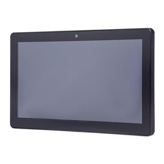
Supports Android and Debian Front Panel The PPC-112W/115W front panel is a true-flat color TFT LCD touchscreen with Pro- jected Capacitive Multi-Touch. The front panel is IP65 rated for dust and water toler- ance (Figure 1.1). Aluminum Frame... -
Page 13: Rear Panel
Rear Panel The PPC-112W/115W rear panel features four VESA mount (100 x 100 mm/3.93 x 3.93 in) holes located on its bottom side, as demonstrated below: VESA mount screws: 4 x M4 screws Screw depth: 8 mm/0.31 in (max.) Figure 1.2 Rear Panel Panel Bottoms The system’s I/O, located on the bottom of the device, (Figures 1.3) are listed below:... -
Page 14: Dimensions
Dimensions Figure 1.4 PPC-112W Dimensions Figure 1.5 PPC-115W Dimensions PPC-112W/115W User Manual... -
Page 15: Specifications
10 ~ 95% @ 40° C/104° F (non-condensing) Shock 10 G peak acceleration (11 ms duration), in accordance with IEC 60068-2-27 Random vibration test 5 ~ 500 Hz, 0.5 Grms, in accordance with IEC 60068- Vibration 2-64 PPC-112W/115W User Manual... -
Page 16: Ordering Information
PPC-112W-PK91A PPC-115W-PK91B All-in-One Panel PC with Rockchip PPC-112W-PK92DA RK3399 processor PPC-115W-PK92DB 98R3P115W10 Wi-Fi module with antenna 98R3P112W00 Panel mount kit for PPC-112W 98R3P115W00 Panel mount kit for PPC-115W PPC-ARM-A03 Arm mount VESA standard PPC-174T-WL-MTE Wall mount kit PPC-112W/115W User Manual... - Page 17 PPC-Stand-A1E Stand kit PPC-112W/115W User Manual...
- Page 18 PPC-112W/115W User Manual...
-
Page 19: Chapter 2 System Installation And Setup
Chapter System Installation and Setup SD card Installation Wireless LAN Card Installation Mounting the System... -
Page 20: Transport And Unpacking
Installation Procedures When installing system hardware, adhere to the following order: Install peripheral devices Mount the panel PC Configure the system 2.2.1 SD Card Installation Remove screw of SD card bracket. Figure 2.1 Remove SD card bracket PPC-112W/115W User Manual... -
Page 21: Wireless Lan Card Installation
Figure 2.2 Insert SD card 2.2.2 Wireless LAN Card Installation PPC-112w/115w provides M.2 key Express slot and allows users to expend functions like Wi-Fi and Bluetooth type modules. Remove 6pcs screws as below figure, and then remove the rear cover. - Page 22 Figure 2.5 Antenna cable assemble on rear cover Connect the antenna cables with wireless LAN card. Figure 2.6 Connect antenna cable with wireless LAN card Assemble rear cover, and install external antenna. Figure 2.7 Location of external antenna PPC-112W/115W User Manual...
-
Page 23: Mounting The System
Drill two pilot holes at the marked locations on the wall. Align the wall mount plate screw holes with the pilot holes. Secure the mount plate to the wall by inserting screws into the two pilot holes and tightening them. Figure 2.8 Wall mount plate PPC-112W/115W User Manual... - Page 24 To mount the panel PC on the wall, align the wall mount bracket attached to the panel PC with the wall mount plate on the wall and slide the panel PC down- wards to hang the bracket on the mount plate. Figure 2.10 Mounting the panel PC on a wall PPC-112W/115W User Manual...
-
Page 25: Panel Mounting Kit 98R3P112W00 Installation With Ppc-112W
Secure the panel PC in place by tightening screws in the wall mount bracket. Figure 2.11 Securing the panel PC 2.3.2 Panel Mounting Kit 98R3P112W00 Installation with PPC-112W Packing List Please check and ensure the following items are in the kit box before installation:... - Page 26 Figure 2.13 Install panel mount cover bracket Install 2pcs panel mount brackets on both sides of PPC-112W with 4pcs M4*6L screws (shows in blue circle). Finally, fix them with 4pcs M6*12L panel mount screws (shows in red circle).
- Page 27 Figure 2.16 Panel mount front view Figure 2.17 Panel mount rear view PPC-112W/115W User Manual...
-
Page 28: Panel Mounting Kit 98R3P115W00 Installation With Ppc-115W
Panel mounting kit installation Remove 4 rubbers and 4 screws from rear cover, and reserve the 4 screws for next step. Figure 2.18 Remove rear cover Stick sponge-H & sponge-V sponges align with panel edge. Figure 2.19 Stick sponge PPC-112W/115W User Manual... -
Page 29: Arm Mounting
2.3.4 Arm Mounting PPC-112W/115W can be mounted on a VESA-compliant arm mount with a 100 mm (3.93 in) interface pad. To affix the panel PC to an arm mount, follow the steps below. Refer to the installation instruction of the mounting arm to correctly mount the arm onto the surface as a base. -
Page 30: Stand Mounting
Retrieve the VESA mount. Line up the screw holes of the VESA mount with the screw holes at the rear of the panel PC. Use the four screws to affix the VESA mount to the panel PC. Figure 2.22 VESA mount screw holes PPC-112W/115W User Manual... -
Page 31: Chapter 3 Android 11
Chapter Android 11... -
Page 32: Android 11
You can search and download them from internet by yourself. Install Android Software PPC-112W/115W supports boot from SD card or onboard flash. This section will guide you how to build an image for PPC-112W/115W Android system boot media. PPC-112W/115W User Manual... -
Page 33: Create A Bootable Sd Card
Please follow the steps below to create an SD card (not less than 16G) for boot up. If your PC is Windows 10: Unzip the AIM-Android-11-ARM_64-PPC-1XX_yyyy_mm_dd.zip. Use the SD Disk Tool to burn the image. Click the “Create” button to burn the SD card. PPC-112W/115W User Manual... -
Page 34: Install Android 11
Insert the SD card. Power on in PPC. Installing system update. Please Remove the SD Card when PPC show the message "Doing Action suc- ceeded. please remove the sdcard..”. Remove SD card. The Android image will be auto-install. PPC-112W/115W User Manual... -
Page 35: Serial Port Sample
After installing AIM-Android, you will see a Serial application in App list. Users can test serial port with it. After starting the application, you will see: Usage: choose the port, baudrate.(e.g., ttyS1, 9600) About Screen Rotation Control The rotate step of the screen. PPC-112W/115W User Manual... - Page 36 PPC-112W/115W User Manual...
-
Page 37: How To Use Adb Tool In Windows
How to Use ADB Tool in Windows 3.6.1 Install ADB After the connection is built, download & execute “ADBDriverInstaller.exe” to install adb driver. 3.6.2 Create PATH Add adb-tool and create path in windows. PPC-112W/115W User Manual... - Page 38 PPC-112W/115W User Manual...
- Page 39 PPC-112W/115W User Manual...
-
Page 40: Value-Added Services
Realize the device kiosk function, display an application in full screen, and auto- matically start the application after the system is powered on Change the boot animation of the device Black and white list of app Remote message push System security configuration PPC-112W/115W User Manual... - Page 41 Figure 3.2 Apphub Server web If you need more information or specific usage, please refer to the information in the link below or contact us Apphub User Manual?https://shimo.im/docx/KrkEVd7lBXIEBOAJ/ Quick Start Guide for Apphub?https://shimo.im/docx/eNQSx9fGqKojrflv/ PPC-112W/115W User Manual...
- Page 42 PPC-112W/115W User Manual...
-
Page 43: Debian Os Installation
Chapter Debian OS Installation... -
Page 44: Installation
Installation 4.1.1 Prepare an Installation SD Card You should click the “Create” button to burn the SD card. PPC-112W/115W User Manual... -
Page 45: Install Rk3399-Ppc-1Xxw-Debian11
4.1.2 Install RK3399-PPC-1xxw-Debian11 Please power off in PPC. Insert the SD card. Power on in PPC. Installing system update. PPC-112W/115W User Manual... -
Page 46: Hardware Requirements
Remove SD card. The rk3399-ppc-1xxw-Debian11 will be auto-install. 4.1.3 Hardware Requirements The following information represents the requirements necessary to install rk3399- ppc-1xxw-Debian11 successfully. SD card Size - Recommended: 16 G or more PPC-112W/115W User Manual... -
Page 47: Usage
Usage rk3399-ppc-1xxw-Debian11 provides many tools based on X-Windows. Here we mainly introduce some important tools that the user may use frequently. 4.2.1 Terminal Applications-Terminal Emulator, open Terminal as follows: PPC-112W/115W User Manual... -
Page 48: File Manager
4.2.2 File Manager Applications-File Manager, open File Manager as follows: 4.2.3 Browser Chromium browser: PPC-112W/115W User Manual... -
Page 49: Ip Configuration
4.2.4 IP Configuration rk3399-ppc-1xxw-Debian11 gets IP according to DHCP default. If you want to get IP by static, you can use “Applications-Settings- Advanced Network Configuration”. To set static IP. PPC-112W/115W User Manual... - Page 50 Then edit wired connection 1, as follows: first choses IPV4 Settings, then “Method” choose Manual.finally input the Address, netmask, Gateway and DNS information save the config. After that, restart the Network Manager or restart the system, The ip address will become what you set. PPC-112W/115W User Manual...
-
Page 51: Packages Install
There are two ways to update the system. One is using Android Tool to update sys- tem, the other is using “updateEngine” command to update system. 4.4.1 Android Tool Update System Use USB OTG to connect PPC-1xx device and PC. Open AndroidTool.exe. PPC-112W/115W User Manual... - Page 52 Reboot ppc-1xx,and enter uboot, then input “rbrom” command. Click the execute button, In AndroidTool. Then wait for update, The system will restart automatically after the update is completed. PPC-112W/115W User Manual...
-
Page 53: Updateengine Update System
Users can use gcc to develop their own applications on the rk3399-ppc-1xxw-Debi- an11. For example, a simple demo as follows, write a simple program demo.c. And then write a “Makefile” file as follow: Then you can perform as follows: The file “demo” is the executable file user developed. PPC-112W/115W User Manual... - Page 54 PPC-112W/115W User Manual...
-
Page 55: Bsmi Rohs
Appendix BSMI RoHS... -
Page 56: Bsmi Rohs
BSMI RoHS 設備名稱:電腦 型號 (型式) :PPC-115W/PPC-112W Equipment name Type designation (Type) 限用物質及其化學符號 Restricted substances and its chemical symbols 單元 六價鉻 多溴聯苯 多溴二苯醚 Unit 鉛 汞 鎘 Hexavalent Polybrominated Polybrominated Lead Mercury Cadmium chromium biphenyls diphenyl ethers (Pb) (Hg) (Cd) (PBB) (PBDE) 電路板... - Page 57 PPC-115W-PK91A PPC-115W-PK91AU PPC-115W-PK91B PPC-115W-PK91C PPC-115W-PK92A PPC-115W-PK92B PPC-115W-PK92C PPC-115W-PK93A PPC-115W-PK93B PPC-115W-PK93C PPC-115W-PK94A PPC-115W-PK94B PPC-115W-PK94C PPC115W2101-T PPC115W2102-T PPC115W2103-T PPC115W2104-T PPC115W2201-T PPC115W2202-T PPC115W2203-T PPC115W2204-T PPC115W2301-T PPC115W2302-T PPC115W2303-T PPC115W2304-T PPC115W2401-T PPC115W2402-T PPC115W2403-T PPC115W2404-T PPC115W2501-T PPC115W2502-T PPC115W2503-T PPC115W2504-T PPC115W2601-T PPC115W2602-T PPC115W2603-T PPC115W2604-T PPC-112W/115W User Manual...
- Page 58 No part of this publication may be reproduced in any form or by any means, such as electronically, by photocopying, recording, or otherwise, without prior written permission from the publisher. All brand and product names are trademarks or registered trademarks of their respective companies. © Advantech Co., Ltd. 2023...
Need help?
Do you have a question about the PPC-112W and is the answer not in the manual?
Questions and answers