
Related Manuals for Advantech PPC-177T


Summary of Contents for Advantech PPC-177T
- Page 1 User Manual PPC-177T Intel® Core 2 Duo Processor- Based Panel PC with 17” Color TFT LCD Display...
- Page 2 No part of this manual may be reproduced, copied, translated or transmitted in any form or by any means without the prior written permission of Advantech Co., Ltd. Information provided in this manual is intended to be accurate and reliable. How- ever, Advantech Co., Ltd.
-
Page 3: Declaration Of Conformity
This product has passed the CE test for environmental specifications when shielded cables are used for external wiring. We recommend the use of shielded cables. This kind of cable is available from Advantech. Please contact your local supplier for ordering information. -
Page 4: Safety Instructions
The sound pressure level at the operator's position according to IEC 704-1:1982 is no more than 70 dB (A). DISCLAIMER: This set of instructions is given according to IEC 704-1. Advantech disclaims all responsibility for the accuracy of any statements contained herein. - Page 5 Don't touch any components on the CPU card or other cards while the PC is on. Disconnect power before making any configuration changes. The sudden rush of power as you connect a jumper or install a card may damage sensitive elec- tronic components. PPC-177T User Manual...
- Page 6 PPC-177T User Manual...
-
Page 7: Table Of Contents
System Setup ........5 A Quick Tour of the Panel PC ..............6 Figure 2.1 Front Panel of PPC-177T ........... 6 Figure 2.2 Side View of the Panel PC ......... 6 Figure 2.3 I/O Peripheral Connectors Panel........ 7 Figure 2.4 Rear View of the Panel PC......... 7 Preparing for First-time Use .............. - Page 8 Setting Jumpers................28 5.1.2 Jumpers ..................29 5.1.3 Jumper and Connector Locations..........30 Figure 5.1 Jumpers & Connectors on PPC-177T Motherboard. 30 5.1.4 Connectors ................. 30 Table 5.1: CN1 (USB Port 7/8)..........31 Table 5.2: CN2 (CPU FAN Connector) ........32 Table 5.3: CN3 (LVDS2 Connector)..........
- Page 9 Chapter Driver Installation ......41 Introduction ..................... 42 6.1.1 Driver Installation ................ 42 Updating Driver Search on the Advantech Website........ 42 Appendix A PCI Card and PCI-E Size Limits..43 PCI Interface Card .................. 44 PCI-E Interface Card................44 PPC-177T User Manual...
- Page 10 PPC-177T User Manual...
-
Page 11: Chapter 1 General Information
Chapter General Information This chapter gives background information on the PPC-177T. Sections include: Specifications Dimensions... -
Page 12: Introduction
Introduction Advantech PPC-177T is an Intel Core 2 Duo processor based Panel PC with a bright 17" LCD display. The powerful Core 2 Duo CPU and Intel 945GME chipsets bring the most dynamic applications to life without sacrifices to any industrial reliability. The... -
Page 13: Ethernet Interface
PCMCIA interface: Complies wit 1995 PCMCIA card standard 1.2.8 Environment Temperature: 0~50° C (32~122° F) Relative humidity: 10~95% @ 40° C (non-condensing) Shock: 10 G peak acceleration (11 msec duration) 1.2.9 Certifications: EMC: CE, FCC, BSMI, CCC BSMI approved Safety: CE, UL, CB PPC-177T User Manual... -
Page 14: Dimensions
Dimensions Unit: mm (inch) Figure 1.1 Dimensions of PPC-177T PPC-177T User Manual... -
Page 15: Chapter 2 System Setup
Chapter System Setup This chapter gives system setup information for the PPC-177T. Sections include: A Quick Tour Installation Procedures Running the BIOS Setup Installing System software... -
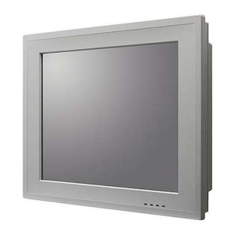
Page 16: A Quick Tour Of The Panel Pc
When placed upright on the desktop, the front panel of the panel PC appears as shown in Figure 2.1. Figure 2.1 Front Panel of PPC-177T When viewed from the left side of the panel PC, the optical device drive, USB ports and PCMCIA expansion sockets are visible, as shown in Figure 2.2. - Page 17 Figure 2.3 I/O Peripheral Connectors Panel VESA standard both 100 x 100 mm and 75 x 75 mm mounting size. 75,00 75,00 100,00 75,00 12,50 106,00 75,00 154,00 100,00 Figure 2.4 Rear View of the Panel PC PPC-177T User Manual...
-
Page 18: Preparing For First-Time Use
CMOS RAM and compares them to the equip- ment check conducted during the power on self-test (POST). If a problem occurs, an error message will be displayed on screen, and the computer prompts the user to run the setup program. PPC-177T User Manual... -
Page 19: Installing System Software
Note! The drivers and utilities used for the PPC-177 panel PCs are subject to change without notice. If in doubt, check Advantech's website or contact our application engineers for the latest information regarding drivers util- ities. - Page 20 PPC-177T User Manual...
-
Page 21: Chapter 3 Using The Panel Pc
Chapter Using the Panel PC This chapter explains onboard devices and peripheral I/O ports available on the PPC-177T. Sections include: CD-ROM Drive PS/2 Mouse and Keyboard PCI or PCI-E Bus Expansion Serial COM Ports VGA Port USB Ports Audio Interface... -
Page 22: Introduction
To install a full-size desktop PS/2 keyboard and mouse with the panel PC, follow these instructions: Be sure the panel PC is turned off. Attach the keyboard to the purple colored 5-pin PS/2 port. Attach the PS/2 mouse to the green colored port. Turn on the panel PC. PPC-177T User Manual... -
Page 23: Pci Or Pci-E Bus Expansion
Remove the metal plate by unscrewing the attaching screw. Insert the PCI or PCI-e into the PCI-e slot of the riser card. (See Figure 3.2) Run the setup program within the OS to configure the system. Figure 3.2 PCI & PCI-E Bus Expansion PPC-177T User Manual... -
Page 24: Serial Com Ports
The panel PC simultaneously supports an external CRT monitor in addition to the built-in LCD display. Be sure the panel PC is turned off. Connect the external monitor to the system. (See Figure 3.3.) Turn on the panel PC and the external monitor. PPC-177T User Manual... -
Page 25: Usb Ports
Touchscreen (Optional) The touchscreen is connected to the internal USB port. Its function is similar to that of a mouse. There are 3 kinds of touchscreens that support the PPC-177T: Resistive, capacitive and SAW type. It is necessary to install the touchscreen driver before it will function. The touch- screen drivers for various operating systems are stored on the CD-ROM disc inside the accessory box. - Page 26 PPC-177T User Manual...
-
Page 27: Chapter 4 Hardware Installation
Chapter Hardware Installation This chapter gives instructions for installing hardware devices on the PPC-177T. Sections include: Jumpers and Connectors Disassembling the Panel PC Installing the Central Processing Unit (CPU) Installing the DDR SDRAM Mem- ory Module... -
Page 28: Jumpers And Connectors
The following are standard procedures for disassembling the panel PC before upgrading the system. All procedures are illustrated in Figure 4.1, 4.2, 4.3. Unfasten the screws securing the rear plastic cover and remove it. Figure 4.1 Unfastening the Rear Cover PPC-177T User Manual... - Page 29 Before removing the rear cover, disconnect the system fan connector. Figure 4.2 Disconnecting the Fan Connector Figure 4.3 The PPC without the Rear Cover PPC-177T User Manual...
- Page 30 Remove the two screws on side cover first. (See Figure 4.4) Figure 4.4 The PPC Side Cover Remove the four screws on the metal plate of two side of HDD. (See Figure 4.6) Figure 4.5 The PPC HDD PPC-177T User Manual...
- Page 31 Caution! Always disconnect the power cord from your panel PC when you are working on it. Do not make connections while the power is on as sensi- tive electronic components can be damaged by the sudden rush of power. Only experienced electronics personnel should open the panel PPC-177T User Manual...
- Page 32 Place the CPU carefully into the socket, taking care to align it properly. Figure 4.7 Placing the CPU in the Socket Fasten the screw on the CPU socket mounting plate. Figure 4.8 Tightening the Screws on the CPU PPC-177T User Manual...
- Page 33 Installing the DDR2 SDRAM Memory Module The panel PC system provides two 200-pin SODIMM sockets and it is possible to install from 512 MB to 4 GB of DDR2 SDRAM memory. Figure 4.10 Placing the Memory Module in the SODIMM Socket PPC-177T User Manual...
- Page 34 Installing the Optical Device Drive Remove all the screws on the rear cover. Figure 4.11 Rear Cover Photo To loosen the screws on the CD-ROM module. Figure 4.12 Rear Cover Photo with ODD Bracket PPC-177T User Manual...
- Page 35 To loosen the screws on the IO shielding. Figure 4.13 IO shielding To remove the SATA cable from CD-ROM. Figure 4.14 SATA CD-ROM cable PPC-177T User Manual...
- Page 36 PPC-177T User Manual...
- Page 37 Chapter Jumpers and Connectors This chapter gives information on setting jumpers and using the connectors on the PPC-177T motherboard. Sections include: Setting Jumpers Jumpers and Connectors loca- tions Connectors...
-
Page 38: Setting Jumpers
Jumpers and Connectors This chapter supplies more detailed information about the internal jumper settings and an outline of the I/O ports available on the PPC-177T. 5.1.1 Setting Jumpers The Panel PC can be configured to match the needs of each application by setting the jumpers. - Page 39 It also has LED indicator lamps that display the system operation status. The table below lists the function of each jumper and LED. The motherboard of the PPC-177T has a number of jumpers that allow you to config- ure your system to suit your applications.
- Page 40 5.1.3 Jumper and Connector Locations Figure 5.1 Jumpers & Connectors on PPC-177T Motherboard 5.1.4 Connectors Onboard connectors link the panel PC to external devices such as hard disk drives. The table below lists the function of each of connectors. PPC-177T User Manual...
- Page 41 Line OUT connector CN40 Line IN connector CN42 COM2 RI Function Selection connector CN43 COM3 RI Function Selection connector CN44 COM4 RI Function Selection connector CN45 AT Power Solution connector Table 5.1: CN1 (USB Port 7/8) Signal Signal PPC-177T User Manual...
- Page 42 FAN Speed Detection Table 5.3: CN3 (LVDS2 Connector) Signal Signal +5_LVDS0 +V5_LVDS0 +V5_LVDS0 +V5_LVDS0 LVDS2_D0- LVDS3_D0- LVDS2_D0+ LVDS3_D0+ LVDS2_D1- LVDS3_D1- LVDS2_D1+ LVDS3_D1+ LVDS2_D2- LVDS3_D2- LVDS2_D2+ LVDS3_D2+ LVDS2_CLK- LVDS3_CLK- LVDS2_CLK+ LVDS3_CLK+ LVDS2_DCLK LVDS2_DDAT LVDS2_D3- LVDS3_D3- LVDS2_D3+ LVDS3_D3+ LVDS2_BKLTEN PPC-177T User Manual...
- Page 43 LVDS0_D1+ LVDS0_DDAT LVDS0_D2- LVDS0_D2+ LVDS0_DCLK LVDS0_CLK- LVDS0_CLK+ +V3.3_LVDS +V3.3_LVDS Table 5.5: CN5 (System FAN Connector) Signal +V12 FAN Speed Detection Table 5.6: CN8 (SATA HDD Power Connector) Signal +V3.3 +V12 Table 5.7: CN9 (SATA HDD Connector) Signal PPC-177T User Manual...
- Page 44 Table 5.9: CN12 (ATX Power Input Connector) Signal Signal +V3.3 +V3.3 +V3.3 -V12 PS_ON# +V5SB +V12 Table 5.10: CN13 (USB Port 5/6) Signal Signal +V5_USB +V5_USB DAT- DAT- DAT+ DAT+ Table 5.11: CN15 (SPI Reflash Connector) Signal Signal +V3.3 MISO# MOSI PPC-177T User Manual...
- Page 45 +V3.3 +V12 Table 5.14: CN19 (Multi Function PCI Express by1 Connector) Signal Signal +V12 +V12 +V12 +V12 +V12 SATA1_TX+ SMB_CLK SATA1_TX- SMB_DATA SATA1_RX- SATA1_RX+ +V3.3 +V3.3 +V3.3 +V3.3SB PLTRST# PCIE_WAKE# -V12 CLK_PCIE+ CLK_PCIE- PCIE_TX+ PCIE_TX- PCIE_RX+ PCIE_RX- PPC-177T User Manual...
- Page 46 SLIN# ACK# BUSY SLCT Table 5.16: CN22 (LCD Light Sense Connector) Signal SMB_CLK SMB_DATA Table 5.17: CN24 (COM4 Connector) Signal Signal DCD# DTR# DSR# RTS# CTS# Table 5.18: CN25 (Front Panel LED Connector) Signal HDD_LED LAN1_ACT# LAN2_ACT# PPC-177T User Manual...
- Page 47 Table 5.20: CN28 (LCD Back Light Connector) Signal +V12 +V12 LCD_BKLTEN LCD_VBR LCD_DET Table 5.21: CN29 (Power Button Connector) Signal PANSWIN Table 5.22: CN35 (Internal Speaker Connector) Signal OUTA- OUTA+ OUTB+ OUTB- Table 5.23: CN37 (MINIDIN PS2 Connector) Signal KB_DATA MS_DATA KB_CLK MS_CLK PPC-177T User Manual...
- Page 48 +V12 Table 5.26: CN43 (COM3 RI Function Selection Connector) Signal COM3_RI COM3_RI_Selection COM3_RI_Selection +V12 Table 5.27: CN44 (COM4 RI Function Selection Connector) Signal COM4_RI COM4_RI_Selection COM4_RI_Selection +V12 Table 5.28: CN45 (AT Power Solution Connector) Signal But_PANSWIN PANSWIN PPC-177T User Manual...
-
Page 49: Jumper Settings
Table 5.32: CN44 (COM2 RI Function Selection Connector) (1-2) Ring Function (default) (3-4) Ring output 5 V (4-5) Ring output 12 V Table 5.33: CN45 (AT Power Selection) (1-2) ATX power supply (default) (2-3) AT power supply PPC-177T User Manual... - Page 50 PPC-177T User Manual...
- Page 51 Chapter Driver Installation This chapter gives information on installing drivers for the PPC- 177T. Sections include: Driver Installation Updating Drivers...
- Page 52 Before installing the Ethernet driver, note the procedures below. It is necessary to know which operating system is installed on the PPC-177T. Then refer to the corre- sponding installation flow chart. Follow the steps described in the flow chart to com- plete the installation quickly.
- Page 53 Appendix PCI Card and PCI-E Size Limits This chapter details the size limits for PCI and PCI-E cards that may be installed on the Panel PC moth- erboard.
- Page 54 PCI Interface Card PCI-E Interface Card PPC-177T User Manual...
- Page 55 PPC-177T User Manual...
- Page 56 No part of this publication may be reproduced in any form or by any means, electronic, photocopying, recording or otherwise, without prior written permis- sion of the publisher. All brand and product names are trademarks or registered trademarks of their respective companies. © Advantech Co., Ltd. 2009...
Need help?
Do you have a question about the PPC-177T and is the answer not in the manual?
Questions and answers