Table of Contents
Advertisement
Quick Links
Advertisement
Table of Contents

Subscribe to Our Youtube Channel
Related Manuals for Harvia Griffin Combi CG170C


Summary of Contents for Harvia Griffin Combi CG170C
- Page 1 HARVIA GRIFFIN COMBI Control unit Ridici jednotka 03122007...
-
Page 2: Table Of Contents
Congratulations on making an excellent choice! Gratulujeme k dobremu vyberu kamen. CONTENTS Obsah 1. HARVIA GRIFFIN COMBI ........3 1. HARVIA GRIFFIN COMBI ......... 3 1.1. General ........... 3 1.1. Obecne..........3 1.2. Technical Data ........3 1.2. Technicke informace ........ 3 1.3. -
Page 3: Harvia Griffin Combi
1. HARVIA GRIFFIN COMBI 1. HARVIA GRIFFIN COMBI 1.1. General 1.1. Obecne The purpose of the Harvia Griffin Combi control unit Jednotka Griffin Combi je navrzena pro is to control an electric sauna heater and steamer, ovladani kamen s vyparnikem. -
Page 4: Troubleshooting
The humidity sensor WX325 measures NTC-Termistor • temperature and relative humidity. (22 k Ω /T=25 °C). Weight 175 g with leads (ca 4 m) Vlhkostni cidlo WX325 • • Dimensions: 51 mm x 73 mm x 27 mm • Vaha 175 g a kabel (ca 4 m) •... -
Page 5: Instructions For Use
2. INSTRUCTIONS FOR USE 2. Instrukce pro pouziti 2.1. Using the Heater and the Steamer 2.1. Pouzivani kamen a vyparniku When the control unit is connected to the power Kdyz je kontrolni panel pripojen supply and the main switch (see figure 1) is a hlavni spinac na power boxu switched on, the control unit is in standby mode sepnut. -
Page 6: Heater And/Or Steamer Off
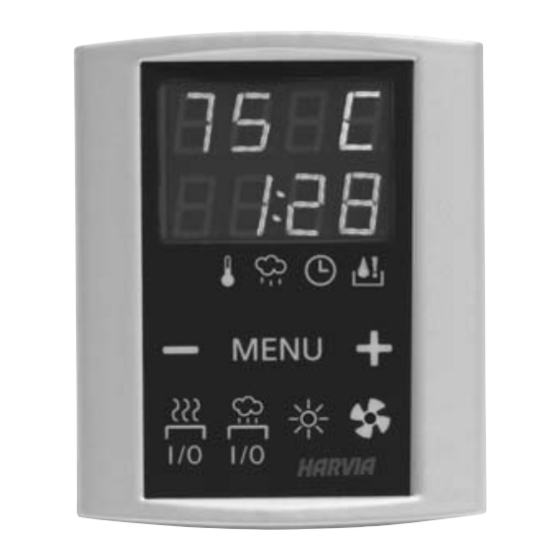
2.1.2. Heater and/or Steamer Off 2.1.2. Vypnuti kamen a vyparniku The heater and/or steamer turn off and the control unit switches to standby-mode when Topidlo je vypnuto a ridici jednotka je prepnuta the I/O button is pressed • do pohotovostního režimu po stisknutí tlacitka I/O, the on-time has elapsed or •... - Page 7 BASIC SETTINGS/ZAKLADNI NASTAVENI Basic mode (heater and steamer on) Zakladni moc (kamna a vyparnik zapnuty) The top row shows the sauna room Horni radek ukazuje teplotu temperature. The bottom row shows the v saune. Spodni radek ukazuje humidity level (or remaining on-time, if the vlhkost sauny nebo cas pokud je steamer is not activated).
- Page 8 ADDITIONAL SETTINGS/DALSI NASTAVENI Control unit standby Usporny rezim I/O buttons’ background lights glow on the I/O tlacitko sviti na ovladacim panelu. control panel. Open the settings menu by simultaneously Otevrete menu nastaveni tim, ze soucasne pressing the control panel buttons –, stisknete tlacitka -, MENU and +.
-
Page 9: Instructions For Installation
3. INSTRUCTIONS FOR INSTALLATION 3. INSTRUKCE PRO INSTALACI Zapojeni ridici jednotky muze byt provedeno pouze The electrical connections of the control unit elektrikarem v souladu se soucasnymi may only be made by an authorised, professional electrician and in accordance with the current predpisy. -
Page 10: Electrical Connections
3.2.1. Electrical Connections 3.2.1. Zapojeni elekriny Figures 6 and 7 show the electrical connections Obrazek 6 a 7 zobrazuje elektricke zapojeni of the power unit. Tables 2 and 3 show the wire POWER BOXU. Tabulky 2 a 3 zobrazuji vodice and fuse sizes, depending on the heater output. - Page 11 Hneda Modra Zluta Cervena Bila Modra...
-
Page 12: Installing The Temperature Sensor
je problem se svetlem nebo ventilatorem. is a problem with lighting or fan. Check the wiring and functioning of lighting and fan. Zkontrolujte kabely s funkcnost svetla a ventilatoru. 3.3. Installing the Temperature Sensor 3.3. Instalace teplotniho cidla Wall-mounted heaters (see figure 8) Kamna pripevnena na zed (obr. -
Page 13: Installing The Humidity Sensor
3.4. Installing the Humidity Sensor 3.4. Instalace cidla vlhkosti Fasten the humidity sensor on the wall as far from Cidlo umistime na stenu jak vidite na obrazku the heater as possible and at a distance of 500–700 8 a 9 do mist 50 až 70 cm pod stropem. mm from the ceiling. -
Page 14: Resetting The Overheat Protector
Vlhkostni cidlo WX325 4 Data cable 5 m Datovy kabel 5 m WX311 5 Data cable extension (optional) 10 m Datovy kabel l (ovladaci) 10 m WX313 6 Circuit board Zakladni deska WX356 Harvia Oy PL 12 FI-40951 Muurame www.harvia.fi...
Need help?
Do you have a question about the Griffin Combi CG170C and is the answer not in the manual?
Questions and answers