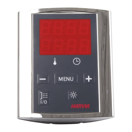
Harvia Griffin Infra CG170I Manual
Hide thumbs
Also See for Griffin Infra CG170I:
- Instructions for installation and use manual (12 pages) ,
- Control unit (10 pages)
Table of Contents
Advertisement
Quick Links
Advertisement
Table of Contents

Summary of Contents for Harvia Griffin Infra CG170I
- Page 1 HARVIA GRIFFIN INFRA Control unit Steuergerät 30012008...
-
Page 2: Table Of Contents
Congratulations on making an excellent choice! Wir beglückwünschen Sie zu Ihrer guten Wahl! CONTENTS INHALT 1. HARVIA GRIFFIN INFRA ........3 1. HARVIA GRIFFIN INFRA ........3 1.1. General ........... 3 1.1. Allgemeines ..........3 1.2. Technical Data ........3 1.2. -
Page 3: Harvia Griffin Infra
1. HARVIA GRIFFIN INFRA 1.1. General 1.1. Allgemeines The purpose of the Harvia Griffin Infra control unit Der Zweck des Steuergeräts Harvia Griffin Infra is to control 1–8 infrared radiators. The maximum ist es, 1–8 Infrarotstrahler zu regeln. Die maxima- total output of the radiators is 3.6 kW. -
Page 4: Instructions For Use
Description/Beschreibung Remedy/Abhilfe Temperature sensor's measuring Check the blue and brown wires to the temperature sensor and their circuit broken. connections (see figure 7) for faulties. Messkreis des Temperaturfühlers Prüfen Sie die blauen und braunen Kabel zum Temperaturfühler und unterbrochen. deren Verbindungen (siehe Abb. 7) auf Fehler. Temperature sensor's measuring Check the blue and brown wires to the temperature sensor and their circuit short-circuited. -
Page 5: Radiators Off
2.2. Radiators Off 2.2. Infrarotstrahler aus The radiators turn off and the control unit switches Die Strahler wird ausgeschaltet und das Steuergerät to standby-mode when schaltet in den Standby-Modus um, wenn the I/O button is pressed die I/O-Taste gedrückt wird •... - Page 6 ADDITIONAL SETTINGS/WEITERE EINSTELLUNGEN Control unit standby Standby des Steuergeräts I/O button’s background light glows on the Die Kontrollleuchte der I/O-Taste leuchtet auf dem control panel. Bedienfeld. Open the settings menu by simultaneously Öffnen Sie das Einstellungsmenü, indem Sie pressing the control panel buttons –, auf dem Bedienfeld gleichzeitig die Taste –, MENU and +.
-
Page 7: Instructions For Installation
3. INSTRUCTIONS FOR INSTALLATION 3. INSTALLATIONSANLEITUNG The electrical connections of the control unit may Die elektrischen Anschlüsse des Steuergeräts dür- only be made by an authorised, professional electri- fen nur von einem autorisierten, geschulten Elektri- cian and in accordance with the current regulations. ker unter Beachtung der aktuell gültigen Vorschrif- When the installation of the control unit is com- ten vorgenommen werden. -
Page 8: Installing The Power Unit
Note! Do not install the temperature sensor closer Achtung! Der Temperaturfühler darf nicht näher als than 1000 mm to an omnidirectional air vent or 1000 mm an einen Mehrrichtungs-Luftschlitz oder closer than 500 mm to an air vent directed away näher als 500 mm an einen Luftschlitz angebracht from the sensor. - Page 9 Temperature sensor Temperaturfühler Data cable Control panel Datakabel Bedienfeld Optional, see section 3.1. Wahlweise, Chaining cable siehe Abschnitt 3.1. (see section 3.2.2.) Verbindungskabel (siehe Kapitel 3.2.2.) Fuse for relay outputs Sicherung für Relaisausgänge T2.5 A Ceramic, slow Keramisch, langsam Main switch Hauptschalter Lighting (optional) N N N...
-
Page 10: Installing The Control Panel
2 Data cable 5 m Datakabel 5 m WX311 3 Data cable extension 10 m (optional) Verlängerungskabel 10 m (wahlweise) WX313 4 Temperature sensor Temperaturfühler WX367 5 Circuit board Platine WX366 6 Chaining cable Verbindungskabel WX314 Harvia Oy PL 12 40951 Muurame Finland www.harvia.fi...


Need help?
Do you have a question about the Griffin Infra CG170I and is the answer not in the manual?
Questions and answers