Table of Contents
Advertisement
Advertisement
Table of Contents

Related Manuals for Harvia XENIO CX110


Summary of Contents for Harvia XENIO CX110
- Page 1 XENiO CX110 Control unit Steuergerät 18022016/ZVR-871...
-
Page 2: Table Of Contents
Ofens bzw. des Steuergeräts oder der für die War- tung der anlagen zuständigen Person auszuhändi- CONTrOL UNiT harvia XENiO (CX110) gen. Control unit's purpose of use: the control unit is meant for controlling the functions of a sauna STEUErGEräT harvia XENiO (CX110) -
Page 3: Harvia Xenio
1. harvia XENiO 1.1. General 1.1. allgemeines The purpose of Harvia Xenio control unit is to con- Der Zweck des Steuergeräts Harvia Xenio ist es, ei- trol an electric sauna heater within an output range nen elektrischen Saunaofen innerhalb einer Ausgangs- of 2.3–11 kW. -
Page 4: Troubleshooting
1.3. Troubleshooting 1.3. Störungsbeseitigung If an error occurs, the heater power will cut off and Wenn eine Störung auftritt, wird der Ofen abge- the control panel will show an error message ”E schaltet, und auf dem Bedienfeld wird eine Fehler- (number)”, which helps troubleshooting the cause meldung im Format “E (Nummer)”... -
Page 5: Instructions For Use
2. iNSTrUCTiONS FOr USE 2. BEDiENUNGSaNLEiTUNG 2.1. Using the heater 2.1. verwendung des Ofens When the control unit is connected to the pow- Wenn das Steuergerät an die Stromversorgung an- er supply and the main switch (see figure 1) is geschlossen ist und der Hauptschalter (siehe Ab- switched on, the control unit is in standby mode bildung 1) betätigt wird, befindet sich das Steu-... -
Page 6: Changing The Settings
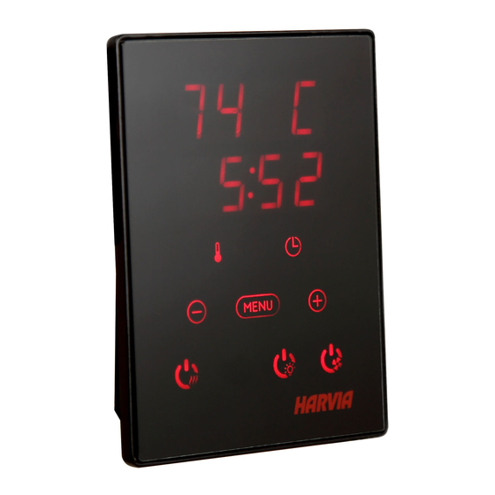
has elapsed, the dehumidification has ended or the die Einschaltzeit abgelaufen ist, die Entfeuchtung heater has been switched off manually. beendet wurde bzw. der Ofen manuell ausgeschal- tet wurde. 2.2. Changing the Settings 2.2. ändern der Einstellungen The settings menu structure and changing the Die Struktur des Einstellungsmenüs und das Ändern settings is shown in figures 3a and 3b. - Page 7 BaSiC SETTiNGS/GrUNDEiNSTELLUNGEN Basic mode (heater on) Basis-Modus (Ofen ein) The top row shows the sauna room Die obere Zeile zeigt die Temperatur in der temperature. The bottom row shows the Saunakabine an. Die untere Zeile zeigt die remaining on-time. Both indicator lights verbleibende Einschaltzeit an.
- Page 8 aDDiTiONaL SETTiNGS/WEiTErE EiNSTELLUNGEN Control unit standby Standby des Steuergeräts I/O button’s background light glows on the Die Kontrollleuchte der I/O-Taste leuchtet auf dem control panel. Bedienfeld. Open the settings menu by simultaneously Öffnen Sie das Einstellungsmenü, indem Sie pressing the locations of the buttons –, gleichzeitig die Taste -, MENU und + drücken MENU and + (see figure 2).
-
Page 9: Instructions For Installation
3. iNSTrUCTiONS FOr iNSTaLLaTiON 3. iNSTaLLaTiONSaNLEiTUNG The electrical connections of the control unit Die elektrischen anschlüsse des Steuergeräts dür- may only be made by an authorised, professional fen nur von einem autorisierten, geschulten Elektri- electrician and in accordance with the current ker unter Beachtung der aktuell gültigen vorschrif- regulations. -
Page 10: Installing The Power Unit
be at the minimum safety distance from the heater der Sauna montiert, muss es in der Saunawand auf and at a maximum height of one metre from the max. 1 m Höhe eingelassen werden. Eine aufge- floor. Figure 4. setzte Montage ist nicht erlaubt. Auch der Mindest- Conductor tubing (ø... - Page 11 Control of electric heating Steuerung der elektrischen Heizung Temperature sensor (3=red, 4=yellow) Temperaturfühler (3=rot, 4=gelb) Overheat protector (1=blue, 2=white) Überhitzungsschutz (1=blau, 2=weiß) Control panel Bedienfeld POWER SUPPLY 5 x 2,5 mm² 5 x 2,5 mm² HAUPTZENTRALE 3 x 1,5 mm² 3 x 1,5 mm²...
-
Page 12: Power Extension Unit Lty17 (Optional)
3.2.3. Power extension unit LTY17 (optional) 3.2.3. Optionale Leistungseinheit LTY17 The maximum load of control unit can be increased (wahlweise) by 17 kW by using power extension unit LTY17. Die maximale Belastung der Steuereinheit kann mit The power extension unit includes detailed instruc- zusätzlicher Leistungseinheit LTY17 um 17 kW er- tions of installation. - Page 13 min. 100 mm max. 200 mm WX232 WX232 WX232 A min. A max. A min. A min. A max. A min. WX232 Tempera- ture sensor Temperatur- Heater A min. A max. D min. fühler Ofen BC105 1250 F10,5 1400 K11G 1200 1250 1250...
-
Page 14: Resetting The Overheat Protector
3.4. resetting the Overheat Protector 3.4. Zurückstellen der Überhitzungsschutzes The sensor box (WX232) contains a temperature Das Fühlergehäuse (WX232) enthält einen Tempe- sensor and an overheat protector. If the raturfühler und einen Überhitzungsschutz. Wenn temperature in the sensor’s environment rises too die Temperatur in der Umgebung des Temperatur- high, the overheat protector cuts off the heater fühlers zu stark ansteigt, unterbricht der Überhit-...
Need help?
Do you have a question about the XENIO CX110 and is the answer not in the manual?
Questions and answers