Floe VSD 6500 Assemnly Instructions
Boat lift
Hide thumbs
Also See for VSD 6500:
- Assembly intructions (40 pages) ,
- Assembly instructions manual (8 pages) ,
- Owner's manual (48 pages)

Related Manuals for Floe VSD 6500


Summary of Contents for Floe VSD 6500
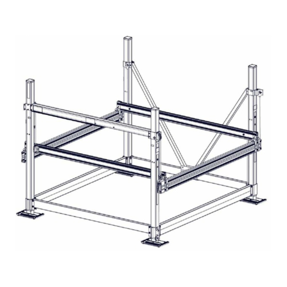
- Page 3 VSD-6500 Frame Exploded View LIFT P/N 511-65075-01 79 96 23 111 SEE SHEET 4 58 79 58 79 63 64 SHEET 3 OF 12...
- Page 4 VSD-6500 Frame Exploded View IMPORTANT: INSERT BOLTS LIFT P/N 511-65075-01 THRU HOLES IN BEARING BLOCK 23 111 IMPORTANT: VERIFY THAT THE LIFTING CABLE IS POSITIONED OVER THE TOP OF THE BALL SCREW SUPPORT BOLT 40 75 SHEET 4 OF 12...
- Page 5 Step 1 Attach sand pads to all four corner post assemblies using (4) 1/2" x 5" bolts and (4) 1/2" nylock nuts. Left Rear Torque to 25 ft/lbs. See Fig 1A. Corner Post Ass'y Left Front Arrange corner posts as shown to the right and in Corner Post Ass'y Fig.
- Page 6 Step 2 3/8" x 4 1/2" Frame beams are fastened to the corner posts 1/2" x 6" using the pre-attached lower clamps. See corner 3/8" x 6" 3/8" x 6" post layout in Fig. 2A. Insert frame beam spacers into ends of all four frame beams before assembly IMPORTANT: INSERT BOLTS THRU HOLES as shown in Fig.
- Page 7 Step 3 Upper Clamp Slide the two lower V-brace clamps together. See Fig. 3A. Locate the Upper Clamp lower V-brace clamps approximately in the center of the side frame beam. Fig. 3C Fasten the V-braces to the lower V-brace clamps w/ (2) 3/8" x 3 1/2" bolts and nylock nuts.
- Page 8 Step 4 Attach the 118" rear frame beam to the assemblied side frames using (4) 1/2" x 4" bolts, (8) flat washers, and (4) nylock Framing nuts. See Fig. 4A. The front frame beam Square is attached the same as the rear but use (2) 1/2"...
- Page 9 Step 5 Cradle U-Clamp Lifting Place the left & right cradle beams on top of Cradle with bolt holes Cable the frame beams with the top cable holes to Lift Clamp towards the inside Clevis the rear. Special attention should be taken of the lift (both ends to insure that the cable ends are in the right and both sides)
- Page 10 Step 6 Locate the cable holder and 4" sheave on the hardware card. Wrap the cable around sheave and attach to the Fig. 6E clamp with a 1/2" x 2 1/2" bolt and nylock nut. Cable Fig. 6D holder is placed at approximately 120 degrees from Fig.
- Page 12 If either limit switch does not stop the lift correctly, contact See diagram below. Place the covers on the battery FLOE customer service and do not use the lift until the boxes and strap it through the slots on the battery problem is corrected.
Need help?
Do you have a question about the VSD 6500 and is the answer not in the manual?
Questions and answers