Floe VSD 6000 Assembly Instructions Manual
Boat lift
Hide thumbs
Also See for VSD 6000:
- Owner's manual (48 pages) ,
- Assembly instructions manual (36 pages) ,
- Assembly instruction manual (12 pages)
Advertisement
Quick Links
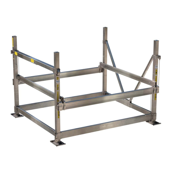
Fl oe VSD 6 0 0 0 Boa t Li f t
P/ N 5 1 1 - 6 0 0 5 5 - 0 1 Li f t Fr a m e
Wi t h Ea sy Lev el Leg s ( Pa t en t Pen d i n g )
Assem b l y I n st r uct i on s
UPDAT ED : 4-0 4-05
P/ N 611-60055-01
SHEET 1 O F 12
TOOLS REQUIRED
(2) 9/ 16" SOCKETS OR
WRENCHES
(2) 3/ 4" SOCKETS OR
WRENCHES
FRAMING SQUARE
TORQUE WRENCH
LOCKING PLIERS
Manufactured by:
Floe International Inc.
48473 State Hwy. 65
McGregor MN.
www.floeintl.com
Advertisement

Related Manuals for Floe VSD 6000


Summary of Contents for Floe VSD 6000
- Page 1 (2) 9/ 16" SOCKETS OR WRENCHES (2) 3/ 4" SOCKETS OR WRENCHES FRAMING SQUARE TORQUE WRENCH LOCKING PLIERS Manufactured by: Floe International Inc. 48473 State Hwy. 65 UPDAT ED : 4-0 4-05 McGregor MN. P/ N 611-60055-01 www.floeintl.com SHEET 1 O F 12...
- Page 2 V SD-6 0 0 0 FRA M E EX PL ODED V I EW PART NO. QTY. DESCRIPTION 001-70215-00 HHCS, 1/2-13 x 3" ss 18-8 PART NO. QTY. DESCRIPTION 911-10501-00 6" FRAME BEAM SPACER 911-10601-00 8" FRAME BEAM SPACER 002-04204-00 CRADLE CLAMP 1.75"...
- Page 3 V SD-6 0 0 0 FRA M E EX PL ODED V I EW 23 109 SEE SHEET 2 SEE SHEET 2 98 80 104 20 22 106 58 80 60 73 61 73 80 63 64 SHEET 3 OF 12...
- Page 4 V SD-6 0 0 0 FRA M E EX PL ODED V I EW 23 108 40 75 50 74 SHEET 4 OF 12...
- Page 5 Fig. 1D ST EP 1 Fig. 1B Left rear Attach sand pads to all four corner post assemblies Fig. 1E corner post ass'y using 1/ 2" x 5" bolts and nylock nuts. Torque to 25 Left front ft/ lbs. See Fig 1A. corner post ass'y Arrange corner posts as shown to the right and in Fig.
- Page 6 ST EP 2 rear frame beam Frame beams are fastened to the corner posts using the pre-attached lower clamps. See clamp layout top view in Fig. 2C. Insert frame beam spacers into ends of all four frame beams before assembly as shown in Fig.
- Page 7 ST EP 3 Upper clamps Slide the two V-brace clamps together and center on the side Upper clamps frame beam. See Fig. 3A. Attach the diagonal V-braces to the V-brace clamps using (2) 3/ 8" x 3" bolts and nylock nuts as shown in V-Braces Fig.
- Page 8 ST EP 4 The 109" ball screw tube is attached using the pre-installed clamps on the corner posts. Orient the tube so the large grease hole is on the side facing out. Pull the cable out the other end so there are no kinks in the cable.
- Page 9 ST EP 5 Attach the lifting cable clevis to the cradle lift clamp using a 3/ 4-16 x 2" bolt (fine thread). Make sure the bolt is seated in the slot of the clamp when tightening the cable clevis. Insert the 2" sheave into the cable loop and attach to to cable clevis using a 3/ 4 x 3"...
- Page 10 ST EP 6 Remove the cable holder and insert the front cable into groove on the sheave. Re-attach the cable holder and sheave to clamp. Wrap Fig. 6E the cable around sheave and attach to the clamp with a 1/ 2" x 2" bolt and nylock nut. Fig.
- Page 11 ST EP 7 Fig. 7A The drive train can now be attached to the clamp on the lift. Note that the rigid coupler on the ball screw and the drive drain mate together. With the drive train being held in place, attach it to the lift clamp using 3/ 8"...
- Page 12 Connect the red wire from the drive train to the positive post of one battery. Connect the black wire from the drive train to the negative post of the other battery. Connect the 32" white battery interconnect wire to the negative post of the first battery and the positive post of the other battery.
Need help?
Do you have a question about the VSD 6000 and is the answer not in the manual?
Questions and answers