inVENTer Pulsar Installation And Operating Instructions Manual
Extractor fan
Hide thumbs
Also See for Pulsar:
- Installation and operating instructions manual (19 pages) ,
- Installation and operating instructions manual (14 pages)
Table of Contents
Advertisement
Quick Links
Advertisement
Table of Contents

Related Manuals for inVENTer Pulsar


Summary of Contents for inVENTer Pulsar
- Page 1 Pulsar extractor fan Installation and operating instructions...
- Page 2 GmbH. The copyright of this document remains with the manufacturer. Rights to all contents and images: © inVENTer GmbH 2016-17. All trademarks used in this document are the property of their respective manufacturers and are hereby acknowledged.
-
Page 3: Table Of Contents
5.1 Creating the wall opening and installing the wall sleeve ........16 PIN code/serial number ..........36 5.2 Installing the PSU (optional) ........18 5.3 Inserting and connecting the Pulsar extractor fan ..........20 5.2 Installing the fan casing’s cover and fan unit ..25... -
Page 4: User And Safety Instructions
USER AND SAFETY INSTRUCTIONS User and safety instructions Thank you for purchasing this high quality product from inVENTer! This section provides an overview of the basic safety precautions for safe and proper operation of your ventilation unit. User information Other symbols used in this documentation... - Page 5 Trouble-free and safe operation of the equipment depends guidelines when working. on proper transportation, proper storage and installation • The Pulsar extractor fan is designed for fixed installation as well as careful operation and maintenance. Observe with permanent cabling. • DANGER: Observe the installation instructions in accor- all safety instructions that are contained in this documen- tation.Any kind of use other than the intended use will...
-
Page 6: System Overview
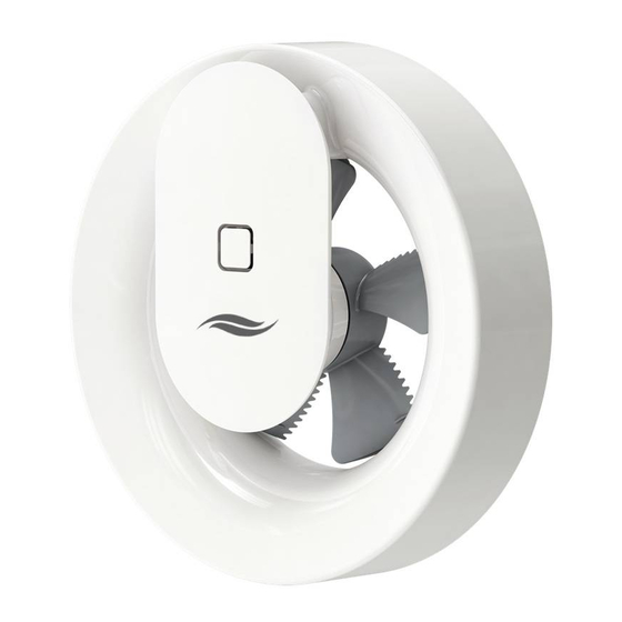
(WC/bath/shower room/laundry room). Furthermore, the Pulsar can be used as a wall-vent fan. The Pulsar can be used in conjunction with the aV100 wall installation set or installed in another wall sleeve with a diameter of 100 – 140 mm (in this case a back-draught Figure 1: Pulsar extractor fan with cover shutter must be retrofitted on site). -
Page 7: Functions
• Sensitivity of the light sensor via the inVENTer Mobile app. • Run-on time • Power-on delay If required, the Pulsar extractor fan can also be used as a • Boost function wall-vent fan for ventilation and heating of adjacent areas, • Intelligent pause function e.g. -
Page 8: Preparing For Installation
Electrical protection areas according to VDE 0100 Positioning in the air flow of the room DANGER Install the Pulsar extractor fan within the air flow of Ingress of water into the Pulsar extractor fan the room. This will ensure optimal humidity extraction or its power source. -
Page 9: Dimensions
Wall sleeves are available in the aV100 wall installation set including weather protection hood, from inVENTer GmbH. A power supply unit is required for the 12 V DC connection. PSU and flush-mounted (plasterboard) box are available from inVENTer GmbH. Dimension drawing Pulsar extractor fan •... -
Page 10: Elektrical Connections
Simultaneous connection of 230 V AC and 12 V DC. Damage to the Pulsar extractor fan! ►Never simultaneously connect the Pulsar extractor fan to 230 V AC and 12 V DC. Electrical connection AC 100 – 240 V (Alternating current) DANGER Exposed electrical components. - Page 11 AC, 3-pole 4 PCB Figure 5: PCB of Pulsar extractor fan: Terminal assignment for power cable connecting terminal (230 V AC) Wiring diagrams for 230 V AC connection The connection of the extractor fan depends on the desired functions.Ensure that you connect the extractor fan correctly and select the correct presets for your desired functions during commissioning.
- Page 12 ELECTRICAL CONNECTION 1 Sensor-controlled, with continuous ventilation: • This setting must be selected via the inVENTer Mobile app. • Continuous ventilation with a flow rate of 30 m³/h. • Increases the fan power with elevated humidity or due to lighting changes.
- Page 13 Figure 6: Wiring diagram for Pulsar extractor fan 230 V AC with sensors activated AC 100 − 240 V DC 12 V Figure 7: Wiring diagram for Pulsar extractor fan 230 V AC, switch-controlled, without run-on function AC 100 − 240 V DC 12 V...
-
Page 14: Electrical Connection 12 V Dc
6 Terminal – (black) 7 Terminal + (red) Figure 9: PCB of Pulsar extractor fan: terminal assignment for connecting terminal 12 V DC Installing the power supply unit (optional) DANGER Exposed electrical components. Electric shock and injury due to live components (230 V, 50 Hz)! ►Before working on electrical installations, disconnect all affected equipment from the power supply. - Page 15 Figure 11: Wiring diagram for flush-mounted PSU NT16 and Pulsar extractor fan 12 V DC Version 4 (switch-controlled) TIP: The S1 switch integrated into the Pulsar extractor fan does not work with a 12 V DC connection. Pulsar extractor fan •...
-
Page 16: Installation
DANGER Ingress of water into the Pulsar extractor fan. Electric shock and overheating due to short circuit (230V, 50Hz)! ►Create wall opening for Pulsar extractor fan outside protection area 0. CAUTION Falling masonry when creating the wall opening. Injury to persons and/or damage to property! ►Use adequate protection against falling masonry. - Page 17 INSTALLATION TIP: The aV100 wall installation set (wall sleeve including back-draught shutter and exterior closure), into which the Pulsar extractor fan can be inserted, is available as an option from inVENTer GmbH. ► Install the aV100 wall installation set ( instructions for aV100 wall installation set).
-
Page 18: Installing The Psu (Optional)
►The connection must only be performed by qualified and trained personnel. DANGER Ingress of water into the Pulsar extractor fan. Electric shock and overheating due to short circuit (230V, 50Hz)! ►Create the wall opening for the power supply unit outside protection area 2. - Page 19 (red, + / black, –) of the PSU using the second enclosed lustre terminal. ► Slide the connected PSU into the flush-mounted box. The power supply unit is installed. Ö Pulsar extractor fan • Installation and operating instructions...
-
Page 20: Inserting And Connecting The Pulsar Extractor Fan
INSTALLATION Inserting and connecting the Pulsar extractor fan Screw driver, drilling machine, rawl plugs, screws, spirit level, wire stripping tool Requirements: The wall sleeve is mounted and any protective discs have been removed. The power/operating voltage cable (230 V, 50 Hz / DC 12 V) is laid. - Page 21 ► Reattach the rubber seal to the back of the fan casing. Ensure that you first place the switch (red arrow) carefully into the opening provided. Then press the rubber seal firmly into the fan casing's base plate. Pulsar extractor fan • Installation and operating instructions...
- Page 22 (red arrows). ► Mark the 3 mounting holes (blue areas). ► Remove the casing from the wall sleeve and drill the holes. Pulsar extractor fan • Installation and operating instructions...
- Page 23 Ensure that the voltage cable is laid through the cable entry. This ensures that the cables do not interfere with the installation of the fan unit and prevents malfunctions of the extractor fan. DC 12 V Pulsar extractor fan • Installation and operating instructions...
- Page 24 ► Connect the shortened voltage cable (in accordance with the wiring diagram) to the terminal block. DC 12 V − The Pulsar extractor fan is inserted and the voltage cable is connected. Ö Pulsar extractor fan • Installation and operating instructions...
-
Page 25: Installing The Fan Casing's Cover And Fan Unit
► Press the upper part of the fan casing's cover onto the bracket (red arrow) on the fan casing's base plate. Ensure that the lock button (red arrow) clicks into place between the guides for the fan unit. Pulsar extractor fan • Installation and operating instructions... - Page 26 ► Ensure that the fan can rotate freely before switching it on. ► Connect the Pulsar extractor fan to the power supply. ► Switch on the device: 230 V AC: The switch is located on the left side of the fan AC 230 V casing.
-
Page 27: Commissioning
Direct pairing with Bluetooth Smart leads to installation errors and the Pulsar must be de-installed (Before reset, deactivate the Auto pairing function in Bluetooth Smart!). Different functions and settings are available within the app depending on the electrical connection of the Pulsar extractor fan. Requirements for app functionality: •... -
Page 28: Operation
• The pulsar must be displayed as active on the mobile Pulsar: device. • At any given time, the Pulsar can only be operated from Configuration of: one mobile device. Simultaneous control of the same • Fan speed (depending on sensor) Pulsar from multiple mobile devices is not possible. -
Page 29: Status Led
The LED only lights up in the following cases: Blue LED illuminated: A blue LED on the fan unit of the Pulsar extractor fan indi- cates that an active Bluetooth Smart connection to a mobile device has been established. -
Page 30: Cleaning And Maintenance
Any necessary cleaning or maintenance work can be carried out by the user by following these instructions. The Pulsar extractor fan has a scratch-resistant plastic casing. Do not use sand, soda, acid or chlorine-based The maintenance tasks and intervals listed here are cleaning agents. - Page 31 Requirements: The power supply is disconnected. 230 V AC: Disconnect the switch on the Pulsar extractor fan. The switch is located on the left side of the fan casing. Push it down into position 0. 12 V DC: Disconnect the power supply at the mains fuse or the external switch.
-
Page 32: Specifications
SPECIFICATIONS Specifications Pulsar extractor fan Feature Value Protection class Type of protection IP44 Input voltage 100 – 240 V AC or 12 V DC Extract air flow rate (free blowing) [m³/h] Power consumption [W] Noise emission (rated) [dB(A)] 17 – 20 Ambient temperature [°C]... -
Page 33: Delivery
SPECIFICATIONS Air flow characteristic of Pulsar extractor fan Air flow [m³/h] Luftvolumenstrom (m³/h) Scope of supply Component Order number Pulsar 3002-0270 Accessories Component Order number aV100 wall installation set 1001-0159 Flush-mounted switching PSU NT16 1003-0094 Flush-mounted box 60x66 3002-0244 Flush mounted plasterboard box 61x68... -
Page 34: Warranty And Service
Manufacturer guarantee Technical customer service InVENTer GmbH provides a five-year guarantee for the Pulsar extractor fan. This covers premature product wear. For technical support contact our service staff. Further information about the warranty is available at www.inventer.eu/guarantee. -
Page 35: Company Details
CEO: ANNETT WETTIG VAT ID NUMBER: DE 815494982 JENA DISTRICT COURT HRB 510380 PICTURE CREDITS/ALL RIGHTS RESERVED: © INVENTER GMBH 2016 – 17 ALL INFORMATION IS SUPPLIED WITHOUT GUARANTEE. SUBJECT TO MODIFICATIONS. NO LIABILITY IS ACCEPTED FOR PRINTING ERRORS. Pulsar extractor fan •... -
Page 36: Pin Code/Serial Number
PIN code / serial number Important! To activate the inVENTer Mobile app, enter the PIN code or scan it with your phone. You can also find your specific PIN code on the right foot of the fan unit. inVENTer GmbH Ortsstraße 4a...
Need help?
Do you have a question about the Pulsar and is the answer not in the manual?
Questions and answers