SICK CLV 490 Series Operating Instructions Manual
Hide thumbs
Also See for CLV 490 Series:
- Operating instructions manual (266 pages) ,
- Operating instructions manual (270 pages)

Related Manuals for SICK CLV 490 Series


Summary of Contents for SICK CLV 490 Series
- Page 1 C L V 4 9 0 B a r C o d e S c a n n e r A d v a n c e d L i n e P R E L I M I N A R Y...
- Page 2 Microsoft Corporation in the USA and other countries. Netscape Navigator™ is a registered trademark of the Netscape Communications Cooperation, USA. I-ViewPro™ is a registered trademark of EnReach Technology, Inc., USA. © SICK AG · Auto Ident · Germany · All rights reserved 8 008 796/0000/15-10-99...
- Page 3 • Adapting the device to the reading application Section 6.4 Configuring (parameterizing) the CLV, Page 6-5 • Troubleshooting Chapter 8. Troubleshooting, Page 8-1 • Finding information Contents, Page E-5 Index, Page 10-55 8 008 796/0000/15-10-99 © SICK AG · Auto Ident · Germany · All rights reserved...
- Page 4 17. Save the parameter set as a configuration file “*.scl” in the CLV Setup program. The CLV can then be operated with the application-specific settings. © SICK AG · Auto Ident · Germany · All rights reserved 8 008 796/0000/15-10-99...
-
Page 5: Table Of Contents
Count direction of the code position CP and code angle CW ...... 4-6 Mounting and adjusting the device ................4-7 4.3.1 Mounting the CLV ......................4-7 4.3.2 Adjusting the CLV ......................4-8 4.3.3 Adjusting mode ......................4-9 8 008 796/0000/15-10-99 © SICK AG · Auto Ident · Germany · All rights reserved... - Page 6 Function of the tabs in CLV Setup (overview) ........... 6-6 6.4.3 Guide to parameterization menu ................6-9 6.4.4 Configuring the CLV with command strings ............6-17 © SICK AG · Auto Ident · Germany · All rights reserved 8 008 796/0000/15-10-99...
- Page 7 Data sheet CLV 490-1011 bar code scanner ............9-3 Dimensioned drawings - CLV ................... 9-3 9.5.1 Line scanner (without/with heater) ................ 9-3 9.5.2 Line scanner with oscillating mirror (without/with heater) ......9-4 8 008 796/0000/15-10-99 © SICK AG · Auto Ident · Germany · All rights reserved...
- Page 8 10.9 Special applications and procedures ..............10-36 10.9.1 Auxiliary input ......................10-36 10.9.2 Daisy-chain configuration ..................10-39 10.9.3 SICK network (RS 485) ..................10-39 10.9.4 Profibus DP ....................... 10-39 © SICK AG · Auto Ident · Germany · All rights reserved 8 008 796/0000/15-10-99...
- Page 9 10.12.3 Quick clamping device no. 2 016 110 ............10-45 10.13 Supplementary documentation ................. 10-46 10.14 Glossary ..........................10-47 10.15 Index ........................... 10-54 10.16 Bar code examples ....................... 10-59 8 008 796/0000/15-10-99 © SICK AG · Auto Ident · Germany · All rights reserved...
-
Page 10: Sick Ag · Auto Ident · Germany · All Rights Reserved
Contents Operating Instructions CLV 490 Bar Code Scanners (blank page) I-10 © SICK AG · Auto Ident · Germany · All rights reserved 8 008 796/0000/15-10-99... - Page 11 Tab. 5-23: Characteristic data of the “Result 1 ... Result 4” switching outputs ......... 5-20 Tab. 6-1: Extract: Default parameter settings of the line scanner CLV 490-0010/-0011 ..6-2 8 008 796/0000/15-10-99 © SICK AG · Auto Ident · Germany · All rights reserved I-11...
-
Page 12: Sick Ag · Auto Ident · Germany · All Rights Reserved
4-1: Line scanner: replacing the laser warning labels ................ 4-2 Fig. 4-2: Line scanner: position of the securing threads on the CLV ........... 4-3 I-12 © SICK AG · Auto Ident · Germany · All rights reserved 8 008 796/0000/15-10-99... - Page 13 10-3: CLV 490-0010/-0011: Min. and max. reading distance (measured radially) as a function of the focus position at a resolution of 0.35 mm and an aperture angle of α = 56° ........................... 10-5 8 008 796/0000/15-10-99 © SICK AG · Auto Ident · Germany · All rights reserved I-13...
-
Page 14: Sick Ag · Auto Ident · Germany · All Rights Reserved
Fig. 10-29: Front view of quick clamping device no. 2 016 110 with angle bracket no. 2 013 824 ........................10-45 Fig. 10-30: Scannable bar codes with various module widths (print ratio 2:1) ........ 10-59 I-14 © SICK AG · Auto Ident · Germany · All rights reserved 8 008 796/0000/15-10-99... -
Page 15: Notes On This Document
For further information on the design of the bar code scanner or on bar code technology in general, please contact the Auto Ident division at SICK AG. 8 008 796/0000/15-10-99 © SICK AG · Auto Ident · Germany · All rights reserved... -
Page 16: Symbols
This typeface is used for messages output via the terminal interface of the CLV. This symbol is used to mark sections that describe steps carried out with the CLV-Setup program. This symbol refers to additional technical documentation. © SICK AG · Auto Ident · Germany · All rights reserved 8 008 796/0000/15-10-99... -
Page 17: Safety Information
The CLV transfers the data content of the decoded bar codes via its host interface to a host for further processing. Any warranty claims vis-à-vis SICK AG will be rendered invalid if the device is used for any other purpose or if changes are made to the device, also as part of the mounting and electrical installation procedures. - Page 18 EN 60825-1: 1994 + A11 : 1996 CLASS II LASER PRODUCT Max. Output: Pulse duration: Wavelength: Compiles with 21 CFR 1040.10 Fig. 2-1: Laser warning plates on the CLV © SICK AG · Auto Ident · Germany · All rights reserved 8 008 796/0000/15-10-99...
-
Page 19: Quick Stop And Quick Restart
The CLV is designed to cause minimum impact on the environment. It does not contain any silicone-based materials and, therefore, does not represent any problems for paint sprayers in paint shops, for example. 8 008 796/0000/15-10-99 © SICK AG · Auto Ident · Germany · All rights reserved... -
Page 20: Power Requirements
(electronic scrap). See also Section 7.3, Page 7-2. SICK AG currently does not accept delivery of unusable or irreparable devices. © SICK AG · Auto Ident · Germany · All rights reserved 8 008 796/0000/15-10-99... -
Page 21: Product Description
CLV without heater The following are required to start up and operate the CLV: 1. A SICK Connection Module from the AMV/S 60 or AMV 30 series to provide the power supply and connect the data and function interfaces. Available types: - For connection one CLV: AMV 60-011 (no. - Page 22 CLV 490 Bar Code Scanners - or - Alternatively, a non-SICK device with a voltage output of 18 ... 30 V DC pursuant to IEC 742 (functional extra-low voltage) and a minimum power output of 20 W. Cable no. 2 020 264 (3 m) with 15-pin D Sub HD connector and one open end for connecting the CLV to the external power pack.
-
Page 23: Layout
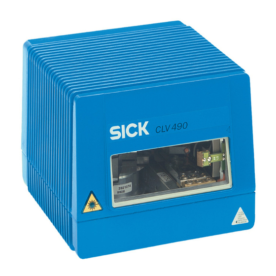
10 mm deep, for connector LEDs cover Tapped blind hole M6, 7 mm Reading window deep, for securing the device “Host/Term” connector Fig. 3-1: CLV 490 8 008 796/0000/15-10-99 © SICK AG · Auto Ident · Germany · All rights reserved... -
Page 24: Method Of Operation
The CLV is operated and configured via the terminal interface (auxiliary interface) using the CLV Setup software or via the host interface/terminal interface using command strings. © SICK AG · Auto Ident · Germany · All rights reserved 8 008 796/0000/15-10-99... -
Page 25: Autofocus Function
Measured distance Optimium focus position: measured distance plus offset for maximum Depth of field (DOF) Fig. 3-3: Optimizing the depth of field for the object 8 008 796/0000/15-10-99 © SICK AG · Auto Ident · Germany · All rights reserved... -
Page 26: Event-Controlled Dynamic Focus Control
• Oscillating with variable deflection amplitude per distance configuration • One-shot: one-off, defined deflection per reading pulse (forward and return phase). © SICK AG · Auto Ident · Germany · All rights reserved 8 008 796/0000/15-10-99... -
Page 27: Additional Components
The LEDs are located on the rear of the device (Fig. 3-5). Device Ready Sensor Read Result Data Fig. 3-5: LEDs 8 008 796/0000/15-10-99 © SICK AG · Auto Ident · Germany · All rights reserved... - Page 28 ” tab in the CLV-Setup program. Download to CLV! TART WITH INTERNAL PARAMETERS EVICE CONFIGURATION Table 3-2: Meaning of LEDs: CLV without external parameter memory © SICK AG · Auto Ident · Germany · All rights reserved 8 008 796/0000/15-10-99...
- Page 29 1) We recommend that you check the parameter set manually, e.g. by printing out the entire configuration. For troubleshooting, see also Section 8.3.2, Page 8-5 2) Stops blinking when you switch from Reading mode to Parameter mode Table 3-3: Meaning of LEDs: CLV with external parameter memory 8 008 796/0000/15-10-99 © SICK AG · Auto Ident · Germany · All rights reserved...
- Page 30 • Blinks bright/dark alternately, in the frequency with which the Show CP limits Sensor green scan line is (partially) masked out Table 3-3: Meaning of LEDs: CLV with external parameter memory (continued) 3-10 © SICK AG · Auto Ident · Germany · All rights reserved 8 008 796/0000/15-10-99...
-
Page 31: Installation
CLV) 4.2.3 Required auxiliary parts • 2 screws M6 for securing the SICK mounting bracket to the base. The screw length depends on the wall thickness of the base. • Set of laser warning labels (if necessary) •... -
Page 32: Replacing The Laser Warning Label
The CLV can be mounted at a maximum distance of 1200 m from the host without a connection to the SICK network or a bus. In practice, however, the distance depends on the physical configuration of the host interface and the data transfer rate. - Page 33 4-3: CLV mounting options using the mounting bracket no. 2 013 824 in combination with the quick-clamping device no. 2 016 110 The dimensions of the mounting brackets are shown in Section 10.12, Page 10-45. 8 008 796/0000/15-10-99 © SICK AG · Auto Ident · Germany · All rights reserved...
-
Page 34: Distance Between The Clv And The Bar Code
Due to the V-principle of beam deflection, the reading field height (for evaluating the useful length of the scan line) depends on the reading distance. © SICK AG · Auto Ident · Germany · All rights reserved 8 008 796/0000/15-10-99... - Page 35 105° with respect to the housing as it passes through the neutral position (CW=50) while oscillating. The device can only be flush-mounted with the conveyor belt with limited 8 008 796/0000/15-10-99 © SICK AG · Auto Ident · Germany · All rights reserved...
-
Page 36: Count Direction Of The Code Position Cp And Code Angle Cw
Configuring the separator: 1. Choose the “D ” tab. ATA STRINGS 2. Click the “S ” field. EPARATOR The “E TFS” dialog box is displayed. ARAMETER © SICK AG · Auto Ident · Germany · All rights reserved 8 008 796/0000/15-10-99... -
Page 37: Mounting And Adjusting The Device
6. Screw the screws M6 through the bracket into the tapped blind holes of the CLV. Tighten the screws slightly. 8. Adjust the CLV as described below. 8 008 796/0000/15-10-99 © SICK AG · Auto Ident · Germany · All rights reserved... -
Page 38: Adjusting The Clv
(CW=50). © SICK AG · Auto Ident · Germany · All rights reserved 8 008 796/0000/15-10-99... -
Page 39: Adjusting Mode
(code position CP=50), is located at the center of the bar code, or at the center of the field for all codes if several bar codes are used. 8 008 796/0000/15-10-99 © SICK AG · Auto Ident · Germany · All rights reserved... -
Page 40: Mounting The External Components
Bar code at the start of the object (Top view) b < a b < a ! Fig. 4-10: Line scanner: mounting example for the external reading pulse sensor 4-10 © SICK AG · Auto Ident · Germany · All rights reserved 8 008 796/0000/15-10-99... - Page 41 ERMANENT The CLV operates with the “Sensor” switching input as an external trigger source. The reading pulse starts when the power supply is connected. 8 008 796/0000/15-10-99 © SICK AG · Auto Ident · Germany · All rights reserved 4-11...
-
Page 42: Mounting The Sensors For Detecting The Object Distance
To do so, click the “D ” button and edit the ISTANCE ONFIGURATION SSIGNMENT ABLE required entries in the dialog box that is then displayed. 4-12 © SICK AG · Auto Ident · Germany · All rights reserved 8 008 796/0000/15-10-99... -
Page 43: Dismantling The Device
When removing the device from service for the last time, please dispose of it in an environ- mentally-friendly manner, as described in Section 7.3, Page 7-2. 8 008 796/0000/15-10-99 © SICK AG · Auto Ident · Germany · All rights reserved 4-13... - Page 44 Installation Chapter 4 Operating Instructions CLV 490 Bar Code Scanners (blank page) 4-14 © SICK AG · Auto Ident · Germany · All rights reserved 8 008 796/0000/15-10-99...
-
Page 45: Electrical Installation
CLV 490 Bar Code Scanners Electrical installation Installation sequence • Connect the CLV to a SICK Connection Module from the series AMV/S, BMV/BMH or BMS, or using a customer-specific wiring configuration • Connect the data and function interfaces of the CLV in the module •... -
Page 46: Electrical Connections And Cables
Connector cover IP 65 with cables pack Table 5-2: Cables for connecting the CLV For technical data on the cables, see Section 10.11.3, Page 10-43. © SICK AG · Auto Ident · Germany · All rights reserved 8 008 796/0000/15-10-99... -
Page 47: Connections/Cables For The Amv/S Connection Module
The AMV/S Connection Module is suitable for connecting the CLV to peripherals (distribu- tion function) and the power supply. The module can be used to establish a connection to the host (point-to-point) or integrate the device in a SICK network or daisy-chain configu- ration (pass-through or master/slave configuration). -
Page 48: Connections/Cables For The Bus Connection Modules Bmv 10 And Bms 20
• Operating Instructions for the “BMV/BMH 10 for Profibus DP Bus Connection Module“ (no. 8 008 825) • Technical Information for the “BMS 20 for Interbus-S Bus Connection Module“ (no. 8 007 546) © SICK AG · Auto Ident · Germany · All rights reserved 8 008 796/0000/15-10-99... -
Page 49: Connections/Cables For The External Parameter Memory (Connection To Amv/S Or Bmv 10/Bms 20)
CLV, the temperature must not drop below max. –40 °C. Recommendation Use the external parameter memory no. 2 020 267 (open cable ends) for connecting the device to external power packs/wiring configurations. 8 008 796/0000/15-10-99 © SICK AG · Auto Ident · Germany · All rights reserved... -
Page 50: Connector Pin Assignment
1) Pin 1 is jumpered with Pin 1 of the Host/Term terminal in the CLV Table 5-4: Pin assignment of the 15-pin D Sub HD I/O socket © SICK AG · Auto Ident · Germany · All rights reserved 8 008 796/0000/15-10-99... -
Page 51: External Parameter Memory No. 2 020 307 (Accessory) Connector Cover No. 2 021 298 (Accessory)
1) Pin 1 is jumpered with Pin 1 of the Host/Term terminal in the CLV Table 5-6: Pin assignment of the 15-pin D Sub HD I/O cable socket 8 008 796/0000/15-10-99 © SICK AG · Auto Ident · Germany · All rights reserved... -
Page 52: Preparations For Electrical Installation
The selected device number (default: 1) affects the power-up delay of the device. This is useful if a large number of CLVs (e.g. in the SICK network) are to be supplied from one power source. Table 5-9 contains a list of the available intervals. -
Page 53: Non-Sick Power Supply Unit/Connections Without The Connection Module
1) Pin 1 is jumpered with Pin 1 of the I/O terminal in the CLV Table 5-10: Wire color assignment of the cable no. 2 020 303 8 008 796/0000/15-10-99 © SICK AG · Auto Ident · Germany · All rights reserved... - Page 54 2 020 981. Connect the free cable ends accordingly. The wire color assignments are shown in Table 5-12 and Table 5-13. CLV with heater: An external parameter memory is not available for this purpose. 5-10 © SICK AG · Auto Ident · Germany · All rights reserved 8 008 796/0000/15-10-99...
- Page 55 1) 1) Pin 1 is jumpered with Pin 1 of the Host/Term terminal in the CLV Table 5-13: Wire color assignment of cable 2 for external parameter memory no. 2 020 981 8 008 796/0000/15-10-99 © SICK AG · Auto Ident · Germany · All rights reserved 5-11...
- Page 56 TD– (RS 422/485), Host grey-brown TxD (RS 232), Host Shield orange Table 5-15: Wire color assignment cable 2 for connector cover no. 2 021 267 5-12 © SICK AG · Auto Ident · Germany · All rights reserved 8 008 796/0000/15-10-99...
-
Page 57: Electrical Installation Procedure
5.5.3 Connecting the supply voltage SICK AMV/S and BMV 10 Connection Modules If the CLV is powered via the SICK Connection Modules, the supply voltage does not have to be wired separately. Connecting the CLV without external parameter memory: 1. Make sure that the power supply to the Connection Module is switched off. -
Page 58: Connecting The Host Interface
SICK (start character: STX, stop character: ETX, no request for repeat: none, timeout: 50 ms) Table 5-16: Communication parameters for the host interface (default setting) 5-14 © SICK AG · Auto Ident · Germany · All rights reserved 8 008 796/0000/15-10-99... -
Page 59: Connecting The Pc
Fig. 5-3: Connecting the terminal interface 1. Switch off the PC and power supply to the SICK Connection Module. 2. Connect the PC to the internal, 9-pin “Service” connector on the Connection Module using an RS 232 connecting cable, e.g. no. 2 014 054 (RxD and TxD crossed). -
Page 60: Connecting The Switching Inputs
For connecting the host interface via the AMV/S 60 Connection Module, see the Operating Instructions for the “AMV/S 60 Connection Module” (no. 8 008 296) Note An external pulse is not required for Percentage Evaluation mode. 5-16 © SICK AG · Auto Ident · Germany · All rights reserved 8 008 796/0000/15-10-99... - Page 61 T. 26 Table 5-18: Pin and terminal assignment for “IN 0 ... IN 4“ switching inputs Connect the sensors as shown in Fig. 5-5. 8 008 796/0000/15-10-99 © SICK AG · Auto Ident · Germany · All rights reserved 5-17...
- Page 62 1) 1 = energized (active); 0 = deenergized (inactive) 2) Distance configuration (DC): data record for focus position Table 5-20: Dynamic focus control: switching inputs/distance configuration assignment table 5-18 © SICK AG · Auto Ident · Germany · All rights reserved 8 008 796/0000/15-10-99...
-
Page 63: Connecting The "Result 1
Table 5-22 shows the pin assignment on the CLV and the terminal assignment in the AMV/S 60. Table 5-23 contains the characteristic data for these outputs. The four outputs have the same characteristic data. 8 008 796/0000/15-10-99 © SICK AG · Auto Ident · Germany · All rights reserved 5-19... - Page 64 To check the switching functions using a high-impedance digital voltmeter, connect a load to the outputs to prevent incorrect voltage values/switching statuses from being displayed. 5-20 © SICK AG · Auto Ident · Germany · All rights reserved 8 008 796/0000/15-10-99...
-
Page 65: Operation
CLV Setup prints out the complete set of default settings in the form of a table. The header contains the company and user names that were entered during the CLV Setup installation routine. 8 008 796/0000/15-10-99 © SICK AG · Auto Ident · Germany · All rights reserved... -
Page 66: Default Settings Of The Line Scanner Clv 490-0010/-0011
50 CW (corresponds to an angle of deflection of 105°) Table 6-2: Extract: Default parameter settings of the line scanner with oscillating mirror CLV 490-1010/-1011 © SICK AG · Auto Ident · Germany · All rights reserved 8 008 796/0000/15-10-99... -
Page 67: Quick Start
Fig. 6-1: Bar code pattern (Code 39; 0.35 mm; Print ratio 2:1) 8 008 796/0000/15-10-99 © SICK AG · Auto Ident · Germany · All rights reserved... -
Page 68: Switching The Clv With External Parameter Memory Connected On For The First Time With The Factory Default Settings
Switching the CLV with external parameter memory connected on for the first time with the factory default settings 1. Connect the CLV to the SICK AMV/S 60 Connection Module via the external param- eter memory no. 2 020 307 using the two cables. -
Page 69: Configuring (Parameterizing) The Clv
Unknown parameters can be edited in the “E ” XTRAS tab by following the conventions for command strings. When the parameter set is then saved, these parameters are also saved. 8 008 796/0000/15-10-99 © SICK AG · Auto Ident · Germany · All rights reserved... -
Page 70: Function Of The Tabs In Clv Setup (Overview)
• Reading distance configuration for event-controlled focus control (focus position, evalua- tion range of the scan line, assignment table) • Trigger source for the focus control © SICK AG · Auto Ident · Germany · All rights reserved 8 008 796/0000/15-10-99... - Page 71 • Test string function • Output sequence and sort criteria for reading more than one bar code per reading pulse • Format mask and its structure 8 008 796/0000/15-10-99 © SICK AG · Auto Ident · Germany · All rights reserved...
- Page 72 CLV Setup Online Help contains a detailed description of the functions of the parameters Note and their valid entries (see Section 10.6.8, Page 10-28 for calling up Help). © SICK AG · Auto Ident · Germany · All rights reserved 8 008 796/0000/15-10-99...
-
Page 73: Guide To Parameterization Menu
The minimum and maximum values for the active evaluation range of the scan line (“M “) can be checked in the “S ” mode. OSITION LIMITS See Section 6.5.5, Page 6-25. 8 008 796/0000/15-10-99 © SICK AG · Auto Ident · Germany · All rights reserved... - Page 74 The minimum and maximum values for the active evaluation range of the scan line (“M “) can be checked in the “S ” mode. OSITION LIMITS See Section 6.5.5, Page 6-25. 6-10 © SICK AG · Auto Ident · Germany · All rights reserved 8 008 796/0000/15-10-99...
- Page 75 7 .1 “O ” tab SCILLATING IRROR “O ” SCILLATING IRROR ACTIVE - continuous - during reading gate Table 6-6: Guide: Parameterizing oscillating mirror functions 8 008 796/0000/15-10-99 © SICK AG · Auto Ident · Germany · All rights reserved 6-11...
- Page 76 This also ensures that the scan line density on the object is, for the most part, constant. Fig. 6-3 illustrates this mode when a bar code is read from above. 6-12 © SICK AG · Auto Ident · Germany · All rights reserved 8 008 796/0000/15-10-99...
- Page 77 Possible trigger sources for one-shot: • “IN 3” or “IN 4“ switching input • Command string (via serial interface) • Reading interval which is initiated by the CLV 8 008 796/0000/15-10-99 © SICK AG · Auto Ident · Germany · All rights reserved 6-13...
- Page 78 Line scanner Conventional reading range Line scanner Reduced reading range (one-shot function) with oscillating mirror Fig. 6-4: One-Shot: Object tracking (bar code read from front) 6-14 © SICK AG · Auto Ident · Germany · All rights reserved 8 008 796/0000/15-10-99...
- Page 79 EADING RIGGER “E ” ND OF EADING NTERVAL - Generated by Trigger Source or - Timer Table 6-7: Guide: Parameterizing the reading trigger source 8 008 796/0000/15-10-99 © SICK AG · Auto Ident · Germany · All rights reserved 6-15...
- Page 80 Format Mask TRINGS Host Interface: • Arrangement in data network ” tab “CLV Arrangement” EVICE ONFIGURATION • Physical interface “H ” tab “Data Format” NTERFACE 6-16 © SICK AG · Auto Ident · Germany · All rights reserved 8 008 796/0000/15-10-99...
-
Page 81: Configuring The Clv With Command Strings
The command is then sent to the CLV. With a few exceptions, the CLV replies to a command with correct syntax with an echo. 8 008 796/0000/15-10-99 © SICK AG · Auto Ident · Germany · All rights reserved 6-17... - Page 82 A detailed description of the command language can be found in the reference manual “Command Language of the CLV Bar Code Scanners” (Order No. 8 007 385). 6-18 © SICK AG · Auto Ident · Germany · All rights reserved 8 008 796/0000/15-10-99...
-
Page 83: Operating Modes And Outputting The Reading Result
See Section 6.3.1, Page 6-3. 4. Ending the reading pulse. The CLV displays the reading result in the output window of the terminal emulator. 8 008 796/0000/15-10-99 © SICK AG · Auto Ident · Germany · All rights reserved 6-19... - Page 84 Decoding direction (F= in scan direction, R= against scan direction) 1) not relevant for autofocus function Fig. 6-7: Reading result of the terminal interface: structure of Good Read 6-20 © SICK AG · Auto Ident · Germany · All rights reserved 8 008 796/0000/15-10-99...
- Page 85 The “Sensor” LED lights up and the scan line appears. 9. Present the bar code pattern from Fig. 6-1, Page 6-3 to the CLV. 8 008 796/0000/15-10-99 © SICK AG · Auto Ident · Germany · All rights reserved 6-21...
-
Page 86: Percentage Evaluation
- LED flashes five times per second if the reading quality is 70% ... 90% - LED is lit continuously if the reading quality is >90% 6-22 © SICK AG · Auto Ident · Germany · All rights reserved 8 008 796/0000/15-10-99... -
Page 87: Adjusting Mode
3. Choose “R ” to exit the Adjusting mode. EADING The CLV returns to the Reading mode and the “Device Ready” LED lights up. 8 008 796/0000/15-10-99 © SICK AG · Auto Ident · Germany · All rights reserved 6-23... -
Page 88: Background Teach-In
S button. UTOFOCUS HOW BACKGROUND The S dialog box appears. HOW BACKGROUND An example of a distance profile is shown in Fig. 6-11. 6-24 © SICK AG · Auto Ident · Germany · All rights reserved 8 008 796/0000/15-10-99... -
Page 89: Show Cp-Limits
UTOFOCUS ” dialog box in the “R ” tab. ISTANCE ONFIGURATIONS EADING ONFIGURATION The CLV does not output a reading result in this mode. 8 008 796/0000/15-10-99 © SICK AG · Auto Ident · Germany · All rights reserved 6-25... - Page 90 5. If necessary, correct CP and CP accordingly. Perform a download to the CLV! 6-26 © SICK AG · Auto Ident · Germany · All rights reserved 8 008 796/0000/15-10-99...
-
Page 91: Displaying And Editing Operating Data
In the default setting, this mode is selected for the terminal interface. Fig. 6-7, Page 6-20 shows the output format of the terminal interface. 8 008 796/0000/15-10-99 © SICK AG · Auto Ident · Germany · All rights reserved 6-27... -
Page 92: Monitor Host Interface
The terminal emulator window is then displayed. The CLV is in the Reading mode. 3. Click the “SW-T ” button or press [F7]. RIGGER The scan line then appears. 6-28 © SICK AG · Auto Ident · Germany · All rights reserved 8 008 796/0000/15-10-99... - Page 93 The selected elements appear in the text box at the top of the dialog box in the sequence in which they were selected. 4. Confirm the entries made by clicking OK. 8 008 796/0000/15-10-99 © SICK AG · Auto Ident · Germany · All rights reserved 6-29...
-
Page 94: Auxiliary Input
3. To return to the Reading mode, click “R ” or close the terminal emulator. EADING The CLV then returns to the Reading mode and the “Device Ready” LED lights up. 6-30 © SICK AG · Auto Ident · Germany · All rights reserved 8 008 796/0000/15-10-99... -
Page 95: Executing Clv Functions Interactively
CLV Setup starts the function and, where appropriate, prompts the user to carry out the necessary actions. Fig. 6-16 shows an example of the dialog box that appears after Show CP-limits has been started. 8 008 796/0000/15-10-99 © SICK AG · Auto Ident · Germany · All rights reserved 6-31... -
Page 96: Clv Messages
Table 6-10 lists the warning messages in alphabetical order together with the associated corrective measures. 6-32 © SICK AG · Auto Ident · Germany · All rights reserved 8 008 796/0000/15-10-99... -
Page 97: Error Messages
3. Make the necessary entries in the dialog box and confirm these. CLV Setup prints out the configuration file in the form of a table. 8 008 796/0000/15-10-99 © SICK AG · Auto Ident · Germany · All rights reserved 6-33... - Page 98 Operation Chapter 6 Operating Instructions CLV 490 Bar Code Scanners (blank page) 6-34 © SICK AG · Auto Ident · Germany · All rights reserved 8 008 796/0000/15-10-99...
-
Page 99: Maintenance
Fig. 7-1 shows the areas that require cleaning. Use a soft, lint-free cloth. : clean here front reading window side reading window Fig. 7-1: Cleaning the reading window 8 008 796/0000/15-10-99 © SICK AG · Auto Ident · Germany · All rights reserved... -
Page 100: Maintenance
5. Send the chassis and cover (aluminium) to be recycled. 6. Send the electronic modules for disposal as problem waste. At present, SICK AG does not accept any unusable or irreparable devices. © SICK AG · Auto Ident · Germany · All rights reserved... -
Page 101: Troubleshooting
“Laser safety timeout” on the terminal interface. The reading interval must be terminated by resetting the trigger signal. The laser diode is activated again by the next reading trigger. 8 008 796/0000/15-10-99 © SICK AG · Auto Ident · Germany · All rights reserved... -
Page 102: Error Messages
The CLV cannot write the Device fault. Contact the SICK Service current parameters in the department. RAM to the EEPROM. Table 8-1: Error messages output on the terminal interface © SICK AG · Auto Ident · Germany · All rights reserved 8 008 796/0000/15-10-99... - Page 103 ” in the ASTER IMEOUT “CLV A ” group. RRANGEMENT Download the changes to the CLV! Table 8-1: Error messages output on the terminal interface (continued) 8 008 796/0000/15-10-99 © SICK AG · Auto Ident · Germany · All rights reserved...
- Page 104 Download any changes to the • RK 512: without reaction the CLV, were changed CLV! subsequently telegram Table 8-1: Error messages output on the terminal interface (continued) © SICK AG · Auto Ident · Germany · All rights reserved 8 008 796/0000/15-10-99...
-
Page 105: Led Error Messages For The External Parameter Memory
2) Flashing stops when the device switches from Reading mode to Parameter mode (e.g. during download from CLV Setup). Table 8-2: LED error messages for access to the external parameter memory 8 008 796/0000/15-10-99 © SICK AG · Auto Ident · Germany · All rights reserved... - Page 106 CLV briefly and monitor the DEVICE READY LED as described under 1. Table 8-2: LED error messages for access to the external parameter memory (continued) © SICK AG · Auto Ident · Germany · All rights reserved 8 008 796/0000/15-10-99...
-
Page 107: Messages For Errors Accessing The External Parameter Memory
It has loaded the internal parameter set to its RAM. Table 8-3: Error messages for problems accessing the external parameter memory 8 008 796/0000/15-10-99 © SICK AG · Auto Ident · Germany · All rights reserved... - Page 108 1) see footnote 1) in Table tolerated errors to its 8-2, Page 8-5 Table 8-3: Error messages for problems accessing the external parameter memory (continued) © SICK AG · Auto Ident · Germany · All rights reserved 8 008 796/0000/15-10-99...
-
Page 109: St Error Status In The Reading Result Of A Bar Code
However, these do not match the active match code(s). Table 8-4: Meaning of the ST error status in the reading result 8 008 796/0000/15-10-99 © SICK AG · Auto Ident · Germany · All rights reserved... - Page 110 6-digit C39 bar codes as C32 bar string instead. codes (output as 9-digit decimal values). Table 8-4: Meaning of the ST error status in the reading result (continued) 8-10 © SICK AG · Auto Ident · Germany · All rights reserved 8 008 796/0000/15-10-99...
-
Page 111: General Malfunctions: Clv Not Ready
Supply new current reading pulse pulse. (pulse type: sensor input/serial interface) Table 8-5: Troubleshooting: restoring operation (Reading mode) 8 008 796/0000/15-10-99 © SICK AG · Auto Ident · Germany · All rights reserved 8-11... -
Page 112: Malfunctions In Reading Mode: Reading Trigger Errors
- the scan line does not “S ” group: is ERIAL NTERFACE appear trigger type correct? Table 8-6: Troubleshooting: reading trigger errors in Reading mode 8-12 © SICK AG · Auto Ident · Germany · All rights reserved 8 008 796/0000/15-10-99... - Page 113 ” button. “E RIGGER ND OF ” group: is EADING NTERVAL “Generated by Trigger Source” selected? Table 8-6: Troubleshooting: reading trigger errors in Reading mode (continued) 8 008 796/0000/15-10-99 © SICK AG · Auto Ident · Germany · All rights reserved 8-13...
-
Page 114: Malfunctions In Reading Mode: Result Output Errors
ONFIGURATION SSIGNMENT ” button. Does the ABLE focus position match the distance of the object? Table 8-7: Troubleshooting: result output errors in Reading mode 8-14 © SICK AG · Auto Ident · Germany · All rights reserved 8 008 796/0000/15-10-99... - Page 115 If necessary, realign CLV and/or reconfigure distance configuration. If ok, choose SMART decoder. Download to CLV. Table 8-7: Troubleshooting: result output errors in Reading mode (continued) 8 008 796/0000/15-10-99 © SICK AG · Auto Ident · Germany · All rights reserved 8-15...
- Page 116 EADING ONFIGURATION “S ” group. Is EGMENTATION “Start/Stop” selected? Perform read with reference code. Table 8-7: Troubleshooting: result output errors in Reading mode (continued) 8-16 © SICK AG · Auto Ident · Germany · All rights reserved 8 008 796/0000/15-10-99...
- Page 117 Is the “T ” RANSMIT HECK IGIT checkbox activated? Change if necessary. Download to CLV! Table 8-7: Troubleshooting: result output errors in Reading mode (continued) 8 008 796/0000/15-10-99 © SICK AG · Auto Ident · Germany · All rights reserved 8-17...
-
Page 118: Malfunctions In Reading Mode: Errors In The Result Status Output
”? UTPUT outputting any pulses Change if necessary. Download to CLV! Table 8-8: Troubleshooting: errors in the result status output in Reading mode 8-18 © SICK AG · Auto Ident · Germany · All rights reserved 8 008 796/0000/15-10-99... -
Page 119: Malfunctions In Reading Mode: Oscillating Mirror Errors
“IN 4“ switching input) function. ” tab. TION Assignment IN 3 or IN 4: is trigger one-shot selected? Table 8-9: Troubleshooting: oscillating mirror errors in Reading mode 8 008 796/0000/15-10-99 © SICK AG · Auto Ident · Germany · All rights reserved 8-19... -
Page 120: Sick Support
• The telephone and fax numbers are listed on the back page of this manual. Please contact SICK before sending the device for repair. 8-20 © SICK AG · Auto Ident · Germany · All rights reserved 8 008 796/0000/15-10-99... -
Page 121: Technical Data
1) in Reading mode with the “Switching input sensor” and “Serial interface” pulse types 2) Reading interval: time window generated internally for evaluating the code Table 9-1: Technical specifications of the CLV 490-0010 8 008 796/0000/15-10-99 © SICK AG · Auto Ident · Germany · All rights reserved... -
Page 122: Data Sheet Clv 490-1010 Bar Code Scanner
(for power supply) Weight approx. 1.5 Kg Ambient operating/storage temperature –35 ... +35 °C/ –20 ... +70 °C Table 9-3: Technical specifications of the CLV 490-0011 © SICK AG · Auto Ident · Germany · All rights reserved 8 008 796/0000/15-10-99... -
Page 123: Data Sheet Clv 490-1011 Bar Code Scanner
M6, 7 mm deep CLV 490-0010 CLV 490-0011 33.4 43.3 Device Ready Sensor Read Result Data Fig. 9-1: Dimensions of the CLV 490 line scanner, front reading window 8 008 796/0000/15-10-99 © SICK AG · Auto Ident · Germany · All rights reserved... -
Page 124: Line Scanner With Oscillating Mirror (Without/With Heater)
M6, 7 mm deep Pin hole, ∅ 3.6, 6 mm deep CLV490 50° Fig. 9-2: Dimensions of the CLV 490 line scanner with oscillating mirror, side reading window © SICK AG · Auto Ident · Germany · All rights reserved 8 008 796/0000/15-10-99... -
Page 125: Appendix
• Instructions for replacing a CLV (copying the parameter set) • Accessories • Dimensioned drawings of the accessories • Supplementary documentation • Glossary • Index • Scannable sample bar codes 8 008 796/0000/15-10-99 © SICK AG · Auto Ident · Germany · All rights reserved 10-1... -
Page 126: Specification Diagrams
CLV 490-1010/-1011: Deflection range as a function of the reading distance, deflection angle, and resolution 10-15 Table 10-3: Overview of specification diagrams for the line scanner with oscillating mirror 10-2 © SICK AG · Auto Ident · Germany · All rights reserved 8 008 796/0000/15-10-99... -
Page 127: Reading Performance Data Line Scanner
CLV 490 Bar Code Scanners 10.2.3 Reading performance data line scanner Fig. 10-1: CLV 490-0010/-0011: Reading field height as a function of the reading distance and resolution 8 008 796/0000/15-10-99 © SICK AG · Auto Ident · Germany · All rights reserved 10-3... - Page 128 10-2: CLV 490-0010/-0011: Min. and max. reading distance (measured radially) as a function of the focus position at a resolution of 0.35 mm and an aperture angle of α = 40° 10-4 © SICK AG · Auto Ident · Germany · All rights reserved 8 008 796/0000/15-10-99...
- Page 129 10-3: CLV 490-0010/-0011: Min. and max. reading distance (measured radially) as a function of the focus position at a resolution of 0.35 mm and an aperture angle of α = 56° 8 008 796/0000/15-10-99 © SICK AG · Auto Ident · Germany · All rights reserved 10-5...
- Page 130 10-4: CLV 490-0010/-0011: Min. and max. reading distance (measured radially) as a function of the focus position at a resolution of 0.50 mm and an aperture angle of α = 40° 10-6 © SICK AG · Auto Ident · Germany · All rights reserved 8 008 796/0000/15-10-99...
- Page 131 10-5: CLV 490-0010/-0011: Min. and max. reading distance (measured radially) as a function of the focus position at a resolution of 0.50 mm and an aperture angle of α = 56° 8 008 796/0000/15-10-99 © SICK AG · Auto Ident · Germany · All rights reserved 10-7...
- Page 132 0.35 mm see Table 10-1, Page 10-2 0.50 mm Fig. 10-6: CLV 490-0010/-0011: scanning frequency as a function of the reading distance and resolution 10-8 © SICK AG · Auto Ident · Germany · All rights reserved 8 008 796/0000/15-10-99...
-
Page 133: Reading Performance Data Line Scanner With Oscillating Mirror
Reading performance data line scanner with oscillating mirror Fig. 10-7: CLV 490-1010/-1011: Reading field height as a function of the reading distance and resolution 8 008 796/0000/15-10-99 © SICK AG · Auto Ident · Germany · All rights reserved 10-9... - Page 134 10-8: CLV 490-1010/-1011: Min. and max. reading distance (measured radially) as a function of the focus position at a resolution of 0.35 mm and an aperture angle of α = 40° 10-10 © SICK AG · Auto Ident · Germany · All rights reserved 8 008 796/0000/15-10-99...
- Page 135 10-9: CLV 490-1010/-1011: Min. and max. reading distance (measured radially) as a function of the focus position at a resolution of 0.35 mm and an aperture angle of α = 50° 8 008 796/0000/15-10-99 © SICK AG · Auto Ident · Germany · All rights reserved 10-11...
- Page 136 Fig. 10-10: CLV 490-1010/-1011: Min. and max. reading distance (measured radially) as a function of the focus position at a resolution of 0.50 mm and an aperture angle of α = 40° 10-12 © SICK AG · Auto Ident · Germany · All rights reserved 8 008 796/0000/15-10-99...
- Page 137 Fig. 10-11: CLV 490-1010/-1011: Min. and max. reading distance (measured radially) as a function of the focus position at a resolution of 0.50 mm and an aperture angle of α = 50° 8 008 796/0000/15-10-99 © SICK AG · Auto Ident · Germany · All rights reserved 10-13...
- Page 138 0.35 mm see Table 10-1, Page 10-2 0.50 mm Fig. 10-12: CLV 490-1010/-1011: scanning frequency as a function of the reading distance and resolution 10-14 © SICK AG · Auto Ident · Germany · All rights reserved 8 008 796/0000/15-10-99...
-
Page 139: Fig. 10-13: Clv 490-1010/-1011: Deflection Range As A Function Of Reading Distance, Deflection Angle And Resolution
0.35 mm see Table 10-1, Page 10-2 0.50 mm Fig. 10-13: CLV 490-1010/-1011: deflection range as a function of reading distance, deflection angle and resolution 8 008 796/0000/15-10-99 © SICK AG · Auto Ident · Germany · All rights reserved 10-15... -
Page 140: Installing And Operating The External Parameter Memory
The Device Ready and Read Result LEDs indicate whether the external memory was accessed successfully. The CLV also outputs plain-text messages for troubleshooting purposes on the terminal interface. 10-16 © SICK AG · Auto Ident · Germany · All rights reserved 8 008 796/0000/15-10-99... -
Page 141: Installation And Electrical Connection
The Device Ready LED blinks for approx. 10 s and then lights up constantly. The data in the CLV is lost when the device is switched off. 8 008 796/0000/15-10-99 © SICK AG · Auto Ident · Germany · All rights reserved 10-17... -
Page 142: Switching On The Device For The First Time
Fig. 10-16: CLV Setup: dialog box for adjusting the external parameter memory Adjust the parameter set in the external parameter memory as described in Section 6.4.1, Page 6-5 10-18 © SICK AG · Auto Ident · Germany · All rights reserved 8 008 796/0000/15-10-99... -
Page 143: Meaning Of The Leds
CLV to CLV Setup and then download it again to the CLV with the P ERMANENT storage option. When asked to do so, adust the external memory again. 8 008 796/0000/15-10-99 © SICK AG · Auto Ident · Germany · All rights reserved 10-19... -
Page 144: Optional Heating
[°C] The temperature enables the operating voltage for the CLV internally time [min] Fig. 10-17: CLV with heater: temperature curve inside the housing 10-20 © SICK AG · Auto Ident · Germany · All rights reserved 8 008 796/0000/15-10-99... -
Page 145: Outdoor Applications
If the CLV with integrated heater is used outdoors, it should be installed in a protective housing to prevent the front window from being damaged by rain, snow, or dust. The housing also acts as a wind protector. 8 008 796/0000/15-10-99 © SICK AG · Auto Ident · Germany · All rights reserved 10-21... -
Page 146: System Messages
Table 10-6: Additional CLV system messages for the connected parameter memory 10-22 © SICK AG · Auto Ident · Germany · All rights reserved 8 008 796/0000/15-10-99... -
Page 147: Installing And Operating The Clv Setup Program
CLV Setup. 6. Then confirm the installation message by clicking OK. The CLV Setup program and CLV Setup Help are installed and ready. 8 008 796/0000/15-10-99 © SICK AG · Auto Ident · Germany · All rights reserved 10-23... - Page 148 2. Choose the deinstallation method (complete or custom). 3. Install the new version of CLV Setup as described under Initial installation, making sure to choose the same directory. 10-24 © SICK AG · Auto Ident · Germany · All rights reserved 8 008 796/0000/15-10-99...
-
Page 149: Starting Clv Setup
The default setting the first time the device is used is the CLV 41x. The software then loads the internal device description for this CLV type and displays the default values on the tabs. 8 008 796/0000/15-10-99 © SICK AG · Auto Ident · Germany · All rights reserved 10-25... -
Page 150: Fig. 10-18: Clv Setup: Results Of The Autobaud Detect Function
CLV Setup then uploads the current parameter set from the RAM of the CLV to its database and displays the values on the tabs. You can edit the current parameter set on the tabs. 10-26 © SICK AG · Auto Ident · Germany · All rights reserved 8 008 796/0000/15-10-99... -
Page 151: User Interface
Some of these parameters open further dialog boxes. • Status bar (bottom right) with device specification field and status of the CLV connection Fig. 10-19: CLV Setup 8 008 796/0000/15-10-99 © SICK AG · Auto Ident · Germany · All rights reserved 10-27... -
Page 152: Functions
5. To display information on a tab, click the tab in the top, horizontal frame. The vertical frame on the left-hand side of the screen then displays a list of parameters. 10-28 © SICK AG · Auto Ident · Germany · All rights reserved 8 008 796/0000/15-10-99... -
Page 153: Transferring Parameter Sets Between Clv Setup And The Clv
7. Compare the two parameter sets. To restore the previous status, correct individual parameters in the problem parameter set if necessary and download them to the CLV again. 8 008 796/0000/15-10-99 © SICK AG · Auto Ident · Germany · All rights reserved 10-29... -
Page 154: Log File In The Terminal Emulator
Windows desktop. In this way, for example, you can prevent CLV Setup from attempting to establish a connection when a CLV is not connected. 10-30 © SICK AG · Auto Ident · Germany · All rights reserved 8 008 796/0000/15-10-99... -
Page 155: Calculating Parameter Values For Setting The Clv
2 m/s the code Code window s = l Fig. 10-21: Line scanner: calculating the number of scans for fence-type bar code arrange- ments 8 008 796/0000/15-10-99 © SICK AG · Auto Ident · Germany · All rights reserved 10-31... -
Page 156: Fig. 10-22: Line Scanner With Oscillating Mirror: Calculating The Number Of Scans For Fence-Type Bar Code Arrangements
= —————— 1.26 Hz n = 476 Fig. 10-22: Line scanner with oscillating mirror: calculating the number of scans for fence-type bar code arrangements 10-32 © SICK AG · Auto Ident · Germany · All rights reserved 8 008 796/0000/15-10-99... -
Page 157: Calculating The Start Position And Mirror Speed For The Forward And Return Phase Of The One-Shot Function
Check the theoretical values on site and adapt them if necessary Fig. 10-23: One-shot: line scanner with oscillating mirror: calculating the number of scans for fence-type bar code arrangements 8 008 796/0000/15-10-99 © SICK AG · Auto Ident · Germany · All rights reserved 10-33... -
Page 158: Calculating The Necessary Bar Code Clearence If Several Bar Codes Are Read On Each Object
INC timer so that the bar codes can be distinguished from one another. Rule of thumb: the blank zone should surround the bar code completely! Fig. 10-24: Required distances between the bar codes on an object 10-34 © SICK AG · Auto Ident · Germany · All rights reserved 8 008 796/0000/15-10-99... -
Page 159: Tables
Table 10-8: Formulas for calculating the code length of a bar code 8 008 796/0000/15-10-99 © SICK AG · Auto Ident · Germany · All rights reserved 10-35... -
Page 160: Special Applications And Procedures
UXILIARY NPUT 5. Download the changes to the CLV by clicking in the toolbar The “D ” dialog box is then displayed OWNLOAD ARAMETERS 10-36 © SICK AG · Auto Ident · Germany · All rights reserved 8 008 796/0000/15-10-99... -
Page 161: Fig. 10-26: Clv Setup: Auxiliary Input On The Terminal Emulator
CLV (via AMV/S 60). For the pin assignment, see Section 5.5.5, Page 5-15. 2. Set the communication parameters and data output format as shown in Table 10- 8 008 796/0000/15-10-99 © SICK AG · Auto Ident · Germany · All rights reserved 10-37... - Page 162 Once the active reading pulse has ended, the CLV sends the data received from the PC to the host via the host interface. If you are using the ST 1100 decoder from SICK, for example, set the communication parameters and data output as shown in Table 10-10 .
-
Page 163: Daisy-Chain Configuration
(order no. 8 007 175, German/English version). 10.9.4 Profibus DP See Operating Instructions “BMV/BMH 10 for Profibus DP” (order no. 8 008 825, English version). 8 008 796/0000/15-10-99 © SICK AG · Auto Ident · Germany · All rights reserved 10-39... -
Page 164: Replacing A Clv (Copying The Parameter Set)
The new device, however, outputs an error message in CLV Setup for each of these parameters/values when the parameter set is downloaded. 10-40 © SICK AG · Auto Ident · Germany · All rights reserved 8 008 796/0000/15-10-99... -
Page 165: 10.10.2 Importing The Parameter Set From The External Memory
8 008 796/0000/15-10-99 © SICK AG · Auto Ident · Germany · All rights reserved 10-41... -
Page 166: 10.11 Accessories
As BMS 20-0113, with integrated power pack 115 V AC 50/60 Hz/ 24 V DC 6 007 655 Power cable, 3-wire, length 3 m, with 3-pin connector (grounding) and one open end (stripped) Table 10-12: Accessories: connection modules 10-42 © SICK AG · Auto Ident · Germany · All rights reserved 8 008 796/0000/15-10-99... -
Page 167: Cables, External Parameter Memories And Plug Covers
Table10-14: Accessories: cables and connector covers for the CLV with heater Note Other cable lengths/types for CLV with heater available on request 8 008 796/0000/15-10-99 © SICK AG · Auto Ident · Germany · All rights reserved 10-43... -
Page 168: 10.11.4 Plug-In Connections
Table10-15: Accessories: plug-in connections 10.11.5 Reading pulse generators The SICK catalog “SENSICK Opto-Electronic Sensors“ (order no. 8 006 530, English version) contains a large selection of photoelectric switches and photoelectric proximity switches as well as the associated accessories (brackets, connection cables) 10.11.6 Network controller... -
Page 169: 10.12 Dimensioned Drawings Of The Accessories
1 x threaded pin M8 x 16 mm No. 2 013 824 Fig. 10-29: Front view of quick clamping device no. 2 016 110 with angle bracket no. 2 013 824 8 008 796/0000/15-10-99 © SICK AG · Auto Ident · Germany · All rights reserved 10-45... -
Page 170: 10.13 Supplementary Documentation
8 007 157 “CLX 200 Network Controller” Description of SICK Network (RS 485) with Technical Description CLV bar code scanners Tab. 10-17: Supplementary documentation 10-46 © SICK AG · Auto Ident · Germany · All rights reserved 8 008 796/0000/15-10-99... -
Page 171: 10.14 Glossary
Calculated by the CLV for each scan and used, for example, to define a capture range so that bar codes with identical data contents in a given range can be separated. 8 008 796/0000/15-10-99 © SICK AG · Auto Ident · Germany · All rights reserved 10-47... - Page 172 ” mode, the deflection range is set SCILLATING SCILLATING WITH VARIABLE MPLITUDE for each distance configuration using the “O ” tab in the CLV Setup program. SCILLATING MIRROR 10-48 © SICK AG · Auto Ident · Germany · All rights reserved 8 008 796/0000/15-10-99...
- Page 173 Distance of the focal point of the emitted laser beam in front of the reading window. Can be varied using the optical components in the CLV. Creates a distance-specific depth of field (DOF) in which the bar code can be detected. 8 008 796/0000/15-10-99 © SICK AG · Auto Ident · Germany · All rights reserved 10-49...
- Page 174 Main data interface on the CLV with configurable data output format. Used to output the reading result in telegram form to the host/PLC. Integrates the CLV in the SICK network or builds a master/slave arrangement. It supports various transmission protocols.
- Page 175 The reading interval may be shorter than the external reading pulse, depending on the selected output mode for the reading result. 8 008 796/0000/15-10-99 © SICK AG · Auto Ident · Germany · All rights reserved 10-51...
- Page 176 Diagrams for reading the resolution-specific depth of field (DOF) for specific focus positions. Standard decoder Tried-and-tested decoder from the CLV product family. Suitable for applications with an adequate code height, limited tilt, and high-quality code prints. 10-52 © SICK AG · Auto Ident · Germany · All rights reserved 8 008 796/0000/15-10-99...
- Page 177 RAM of the CLV. Displays the current parameter values on the tabs. Prerequisite for modifying the current parameter set. User interface Windows-based PC software for operating and configuring the CLV. 8 008 796/0000/15-10-99 © SICK AG · Auto Ident · Germany · All rights reserved 10-53...
-
Page 178: 10.15 Index
- Unknown parameters ........... 10-29 Error messages - Upload ..................6-5 - Display in the terminal emulator ........8-2 - User interface ..............10-27 - Function .................. 3-5 10-54 © SICK AG · Auto Ident · Germany · All rights reserved 8 008 796/0000/15-10-99... - Page 179 - Show CP-limits ..............6-25 - Overview .................. 5-2 Oscillating mirror - Pin assignment ..............5-6 - Deflection range .............. 10-15 Laser radiation - Design ..................3-3 8 008 796/0000/15-10-99 © SICK AG · Auto Ident · Germany · All rights reserved 10-55...
- Page 180 - Function .................. 3-7 Self test - Pin assignment ..............5-7 - Error messages ..............8-2 - Wire colors ................5-12 - Function ................6-30 10-56 © SICK AG · Auto Ident · Germany · All rights reserved 8 008 796/0000/15-10-99...
- Page 181 Terminal emulator ..............6-19 Terminal interface - Connecting ................5-15 - Data format ............6-20, 10-25 - Default settings ..............5-16 - Function .................. 3-4 8 008 796/0000/15-10-99 © SICK AG · Auto Ident · Germany · All rights reserved 10-57...
- Page 182 Appendix Chapter 10 Operating Instructions CLV 490 Bar Code Scanners (blank page) 10-58 © SICK AG · Auto Ident · Germany · All rights reserved 8 008 796/0000/15-10-99...
-
Page 183: 10.16 Bar Code Examples
Module width Module width Module width 0.5 mm 1.0 mm 0.35 mm Fig. 10-30: Scannable bar codes with various module widths (print ratio 2:1) 8 008 796/0000/15-10-99 © SICK AG · Auto Ident · Germany · All rights reserved 10-59... - Page 184 Phone+44 17 27-83 11 21 +1(6 12) 941-928 7 +44 17 27-85 67 67 Representatives and agencies in all major industrial countries. SICK AG · Auto Ident · Nimburger Strasse 11 · 79276 Reute · Germany · http:// www .sick.de...
Need help?
Do you have a question about the CLV 490 Series and is the answer not in the manual?
Questions and answers