Table of Contents
Advertisement
Advertisement
Table of Contents
Troubleshooting

Related Manuals for SICK CLV 45 Series


Summary of Contents for SICK CLV 45 Series
- Page 1 C L V 4 5 x B a r C o d e S c a n n e r A d v a n c e d l i n e...
- Page 2 Microsoft Corporation in the USA and other countries. Netscape Navigator is a registered trademark of the Netscape Communications Cooperation, USA. I-View-Pro is a registered trademark of EnReach Technology, Inc., USA. © SICK AG · Division Auto Ident · Germany · All rights reserved 8 009 139/K949/06-06-2002...
-
Page 3: Finding Information
Help in cases of problems – Chapter 8 Troubleshooting, Page 8-1 • Finding information – Table of contents, Page E-5 – Chapter 10.16 Index, Page 10-66 8 009 139/K949/06-06-2002 © SICK AG · Division Auto Ident · Germany · All rights reserved... - Page 4 Copy the parameter record permanently to the CLV per download. 20. Save the parameter record as a configuration file "*.scl" in CLV-Setup! The CLV is ready to operate with the application-specific setting. © SICK AG · Division Auto Ident · Germany · All rights reserved 8 009 139/K949/06-06-2002...
-
Page 5: Table Of Contents
Installing the AMV/S 40 connection module ............4-11 4.4.2 Installing an external reading-pulse sensor............4-12 4.4.3 Mounting the sensor for detecting the object distance ........4-13 Disassembling the device .....................4-14 8 009 139/K949/06-06-2002 © SICK AG · Division Auto Ident · Germany · All rights reserved... - Page 6 Switching off the CLV......................6-31 Maintenance ........................7-1 Maintenance during operation....................7-1 Maintenance ..........................7-2 Disposal ............................7-2 Troubleshooting ......................8-1 Overview of the possible errors and malfunctions............8-1 © SICK AG · Division Auto Ident · Germany · All rights reserved 8 009 139/K949/06-06-2002...
- Page 7 10.7 Calculating parameter values for setting the CLV.............10-35 10.7.1 Calculating the number of scans (for standard decoders) ......10-35 10.7.2 Calculating the start position and mirror speed for the forward 8 009 139/K949/06-06-2002 © SICK AG · Division Auto Ident · Germany · All rights reserved...
- Page 8 10.12.4 Mounting bracket with vibration damper No. 2 031 342......10-55 10.13 Supplementary documentation ..................10-56 10.14 Glossary ............................ 10-57 10.15 Copy of the EC Declaration of Conformity..............10-64 10.17 Bar code sample........................10-69 © SICK AG · Division Auto Ident · Germany · All rights reserved 8 009 139/K949/06-06-2002...
- Page 9 Troubleshooting: Reading pulsing errors in Reading mode.......8-7 Table 8-5: Troubleshooting: Result output errors in Reading mode........8-9 Table 8-6: Troubleshooting: Errors in the result status output in Reading mode..8-12 8 009 139/K949/06-06-2002 © SICK AG · Division Auto Ident · Germany · All rights reserved...
- Page 10 CLV 44x: Installation example for positioning the object distance detection..........................4-13 Fig. 5-1: Block diagram: Connection of the CLV to the AMV/S 40 connection module............................5-1 E-10 © SICK AG · Division Auto Ident · Germany · All rights reserved 8 009 139/K949/06-06-2002...
- Page 11 0.5 mm and an aperture angle of 25• ................... 10-13 Fig. 10-12: CLV 451-0010: Min. and max. reading distance for the line scanner E-11 8 009 139/K949/06-06-2002 © SICK AG · Division Auto Ident · Germany · All rights reserved...
- Page 12 Fig. 10-34: Reproduction of the declaration of conformity (Page 2, reduced in size) .10-65 Fig. 10-35: Scannable bar codes of various module widths (printing ratio 2:1)....10-69 E-12 © SICK AG · Division Auto Ident · Germany · All rights reserved 8 009 139/K949/06-06-2002...
-
Page 13: Notes On This Document
Further information on the construction of the bar code scanner as well as the bar code technology can be obtained from SICK AG, Auto Ident Division. 8 009 139/K949/06-06-2002 © SICK AG · Division Auto Ident · Germany · All rights reserved... -
Page 14: Symbols Used
Here you have to do something. This symbol characterizes single-step operating instruc- tions. Multiple-step operating instructions are characterized by sequential numbers. Ö Here you select a function in the user interface of CLV-Setup. © SICK AG · Division Auto Ident · Germany · All rights reserved 8 009 139/K949/06-06-2002... -
Page 15: Safety Information
The CLV transfers the data contents of the decoded bar code via the host interface to a host for further processing. The user forfeits any warranty claims against SICK AG in case of any other use as well as in case of changes to the device, also during device installation and electrical installation. -
Page 16: Fig. 2-1: Laser Warning Label Attached To The Clv (Valid For Europe)
(not included in the scope of delivery) must be attached on the machine next to the aperture of the laser beam! © SICK AG · Auto Ident · Germany · All rights reserved 8 009 139/K949/06-06-2002... -
Page 17: Quick Stop And Quick Restart
Switch on the supply voltage or pin up again the cable plug of the CLV to the connection module. The CLV restarts operation with the parameter record last saved permanently and re- sets the day operating data. 8 009 139/K949/06-06-2002 © SICK AG · Division Auto Ident · Germany · All rights reserved... -
Page 18: Environmental Information
(electronic scrap). Refer to Chapter 7.3 Disposal, Page 7-2. At present SICK AG does not take back devices which have become unusable or irreparable. © SICK AG · Auto Ident · Germany · All rights reserved 8 009 139/K949/06-06-2002... -
Page 19: Product Description
3.1.3 System requirements The following are required to start up and operate the CLV: 1. A SICK connection module for power supply and interconnection of the data and function interfaces. Available types: − AMV 40-011 (No. 1 017 132) for 24 V DC ±20 %, enclosure rating max. IP 54 −... - Page 20 CLV 45x Bar Code Scanner – or – Alternatively a non-SICK supply system device with an output voltage of 10 ... 30 V DC in accordance with IEC 742 (functional extra-low voltage) and at least 10 W power out- put. The connection cable No. 6 010 137 with 15-pin D-Sub-HD socket and open cable end to connect the CLV to the supply system device.
-
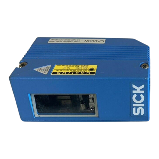
Page 21: Design Line Scanner
Reading window Laser warning lables Connection cable Sound opening of the beepers (concealed) LEDs (status indicators) Fig. 3-1: Design of the line scanner CLV 45x 8 009 139/K949/06-06-2002 © SICK AG · Division Auto Ident · Germany · All rights reserved... -
Page 22: Design Line Scanner With Oscillating Mirror
Sound opening of the beepers (concealed) LEDs (status indicators) Integrated oscillating mirror Reading window Fig. 3-2: Design of the line scanner with oscillating mirror CLV 45x © SICK AG · Division Auto Ident · Germany · All rights reserved 8 009 139/K949/06-06-2002... -
Page 23: Working Method Of The Device
System, warning and error messages provide support in setting up and searching for errors during starting up and reading operation. 8 009 139/K949/06-06-2002 © SICK AG · Division Auto Ident · Germany · All rights reserved... -
Page 24: Changeable Focal Position
• Oscillation with variable deflection per distance configuration • One-Shot: Single defined deflection per reading pulse (forward and return). © SICK AG · Division Auto Ident · Germany · All rights reserved 8 009 139/K949/06-06-2002... -
Page 25: Display And Operating Elements
3-8) are posi- Table 3-2 tioned on the rear narrow side of the device. lists the meaning of the LEDs in the various operating modes/functions. 8 009 139/K949/06-06-2002 © SICK AG · Division Auto Ident · Germany · All rights reserved... -
Page 26: Table 3-2: Meaning Of The Leds
• Flashes alternatively bright/darker in the rhythm of the partial shielding of Orange Show CP limits Laser On the scan line Table 3-2: Meaning of the LEDs © SICK AG · Division Auto Ident · Germany · All rights reserved 8 009 139/K949/06-06-2002... -
Page 27: Function Of The Beeper (Buzzer)
5. Confirm the dialog box with the saving option P ERMANENT The CLV operates the beeper with the selected values for the function of the result status display. 8 009 139/K949/06-06-2002 © SICK AG · Division Auto Ident · Germany · All rights reserved... - Page 28 Chapter 3 Product description Operating Instructions CLV 45x Bar Code Scanner Notes 3-10 © SICK AG · Division Auto Ident · Germany · All rights reserved 8 009 139/K949/06-06-2002...
-
Page 29: Installation
4.2.3 Laying out the required tools ready • Two/three screws M 5 for fastening the SICK mounting bracket to the mounting base. Screw length depends on the wall thickness of the base. • Set of laser warning labels (if required) 8 009 139/K949/06-06-2002 ©... -
Page 30: Replacing The Laser Warning Label
The CLV can be mounted at a max. of 1 200 m from the host without being connected to a SICK network or to a bus connection. However, the possible distance depends on the selected physical implementation of the host interface and the set data transfer rate (refer Table 5-2, Page 5-2). -
Page 31: Mounting Accessories
No. 2 022 564 and the rod clamp N0. 2 023 691 make it possible to rotate the CLV freely. Fig. 4-3: Line scanner: Example of the mounting possibilities of the CLV with the mounting bracket No. 2 020 410 8 009 139/K949/06-06-2002 © SICK AG · Division Auto Ident · Germany · All rights reserved... -
Page 32: Distance Between The Clv And The Bar Code
Fig. 4-7 shows the definition of the reading distance a from the reading window and of the aperture angle α of both scanning processes. © SICK AG · Division Auto Ident · Germany · All rights reserved 8 009 139/K949/06-06-2002... -
Page 33: Table 4-1: Permitted Reading Angle Between The Scan Line And The Bar Code
Rotation γ (skew) Max. ± 45° (depending on module width and focal position) Table 4-1: Permitted reading angle between the scan line and the bar code 8 009 139/K949/06-06-2002 © SICK AG · Division Auto Ident · Germany · All rights reserved... -
Page 34: Counting Direction Of The Code Position Cp And Of The Code Angle Cw
© SICK AG · Division Auto Ident · Germany · All rights reserved 8 009 139/K949/06-06-2002... -
Page 35: Fig. 4-9: Counting Direction Of The Code Position Cp Within The Scan Line And Of The Code Angle Cw At An Oscillating Mirror
The CLV outputs the CP value and the CW value for every bar code in the read result of the host interface. The values are displayed as 3-digit numbers each in the correspond- ing separator. 8 009 139/K949/06-06-2002 © SICK AG · Division Auto Ident · Germany · All rights reserved... -
Page 36: Installation And Adjustment Of The Device
After the start the CLV confirms the successful self-test with a beeper sound and shortly afterwards starting of the reading mode is signaled by two consecutive sounds. The "Device Ready" LED lights up. © SICK AG · Division Auto Ident · Germany · All rights reserved 8 009 139/K949/06-06-2002... - Page 37 In case of different object sizes per defined reading range (distance configuration) check the selected focal position and if necessary correct the parameterization (refer Chapter 6.4.3 Guide to parameterization, Page 6-8). 8 009 139/K949/06-06-2002 © SICK AG · Division Auto Ident · Germany · All rights reserved...
-
Page 38: Auxiliary Functions For Adjusting
For activation of this operating mode and for checking, see Chapter 6.5.4 Show CP limits, Page 6-23 4-10 © SICK AG · Division Auto Ident · Germany · All rights reserved 8 009 139/K949/06-06-2002... -
Page 39: Installing The External Components
For detailed information on the installation and electrical installation refer to the operating instructions "AMV/S 40 connection module" (Order No. 8 008 292, English edition). 4-11 8 009 139/K949/06-06-2002 © SICK AG · Division Auto Ident · Germany · All rights reserved... -
Page 40: Installing An External Reading-Pulse Sensor
8. Check that the cycle is triggered and the read result. 9. Repeat the procedure during transport mode. 10. Check whether the reading process is synchronized with arriving objects. 4-12 © SICK AG · Division Auto Ident · Germany · All rights reserved 8 009 139/K949/06-06-2002... -
Page 41: Mounting The Sensor For Detecting The Object Distance
Have the depth of field determined automatically by means of the CLV Assistant in the CLV-Setup user interface (values are read automatically into the tab cards). 4-13 8 009 139/K949/06-06-2002 © SICK AG · Division Auto Ident · Germany · All rights reserved... -
Page 42: Disassembling The Device
In order to dispose of the unit after final removal from service without damaging the Chapter 7.3 Disposal, Page 7-2. environment proceed as described in 4-14 © SICK AG · Division Auto Ident · Germany · All rights reserved 8 009 139/K949/06-06-2002... -
Page 43: Electrical Installation
The AMV/S 40 connection module is suitable for industrial-type connection of the CLV to the I/O devices (distributor function) and the power supply. The direct connection to the host (point-to-point), the inclusion into the SICK network or into a daisy-chain set-up (pass- through or master/slave configuration) can be realized with it. -
Page 44: Pin Assignment Of The Connecting Plug
Max. 57 600 bits/s Max. 500 m 1) If the cable is terminated correspondingly Table 5-2: Maximum cables lengths between the CLV and the host © SICK AG · Division Auto Ident · Germany · All rights reserved 8 009 139/K949/06-06-2002... -
Page 45: Supply Voltage
Power-up delay The selection of the device number (default setting: 1) influences the power-up delay of the device. This is useful if a large number of CLVs (for example, in the SICK network) is to be supplied from one power source. -
Page 46: Carrying Out The Electrical Installation
Connect the power supply to the red wire (Pin 1, +10 ... +30 V DC) and the black wire (Pin 5, GND) of the Cable No. 6 010 137 (also refer to Table 5-5). © SICK AG · Division Auto Ident · Germany · All rights reserved 8 009 139/K949/06-06-2002... -
Page 47: Wiring The Host Interface
SICK (Start characters STX, Stop characters ETX, No repeat request: None, Timeout: 50 ms) Table 5-6: Communication parameters of the host interface (default setting) 8 009 139/K949/06-06-2002 © SICK AG · Division Auto Ident · Germany · All rights reserved... -
Page 48: Connecting The Can Interface
Instructions for the connection and for configuration of the CLV to use the device in the SICK-specific CAN Scanner Network or in a CANopen network see the operating instructions “Application of the CAN interface“ (no. 8 009 180, English edition) 5.5.6... -
Page 49: Wiring The "Sensor 1" Switching Input
Chapter 5 CLV 45x Bar Code Scanner 1. Switch off the PC and the supply voltage of the SICK connection module. 2. Connect the PC with the internal 9-pin connector "Service" of the connection module. To do so, use an RS-232 data connection cable, for example, No. 2 014 054 (RxD and TxD transposed). -
Page 50: Wiring The "Sensor 2" Switching Input
The wiring of the switching input via the AMV/S 40 connection module is described in the operating instructions "AMV/S 40 connection module" (Order No. 8 008 292, English edition). © SICK AG · Division Auto Ident · Germany · All rights reserved 8 009 139/K949/06-06-2002... -
Page 51: Wiring The "Result 1" And "Result 2" Switching Outputs
Result 2 (Pin 13) T. 5 as for Result 1 output = + 10 ... +30 V DC Fig. 5-6: Wiring of the "Result 1" switching output 8 009 139/K949/06-06-2002 © SICK AG · Division Auto Ident · Germany · All rights reserved... -
Page 52: Table 5-9: Characteristic Data Of The Switching Outputs "Result 1" And "Result 2"
In order to check the switching functions with a high-resistance digital voltmeter wire a load to the outputs. This avoids the display of incorrect voltage values and switching states. 5-10 © SICK AG · Division Auto Ident · Germany · All rights reserved 8 009 139/K949/06-06-2002... -
Page 53: Operation
CLV-Setup prints out the complete default setting in the form of a table. The header contains the company and user names that were entered during the CLV-Setup installation routine. 8 009 139/K949/06-06-2002 © SICK AG · Division Auto Ident · Germany · All rights reserved... -
Page 54: Default Setting Of Line Scanner
50 CW (corresponds to a light emission under 105°) Table 6-2: Extract: Default setting of additional parameter values of the line scanner with oscillating mirror © SICK AG · Division Auto Ident · Germany · All rights reserved 8 009 139/K949/06-06-2002... -
Page 55: Quick-Start
The device can be switched off without the configuration data being lost as no changes have been made to the parameter record. Fig. 6-1: Bar code patter for CLV 450 (Code 39; module width 0.35 mm; Print ratio 2:1) 8 009 139/K949/06-06-2002 © SICK AG · Division Auto Ident · Germany · All rights reserved... -
Page 56: Configuration (Parameterizing)
CLV-Setup runs in offline mode while the CLV is being parameterized. In order to be able to modify the current parameter record of the CLV, this first has to be loaded to CLV-Setup © SICK AG · Division Auto Ident · Germany · All rights reserved 8 009 139/K949/06-06-2002... - Page 57 2. Enter the file name in the dialog box (file name extension "*.scl") and confirm the entry. The new parameter record is now stored in CLV-Setup in the subdirectory "data". 8 009 139/K949/06-06-2002 © SICK AG · Division Auto Ident · Germany · All rights reserved...
-
Page 58: Function Of The Tab Cards In Clv-Setup (Overview)
Active physical interface (RS 422/485 or RS 232) • Data format and transfer rate • Data transfer protocol • Start and stop characters of the interface protocol © SICK AG · Division Auto Ident · Germany · All rights reserved 8 009 139/K949/06-06-2002... - Page 59 The "CLV-Setup Help" online help contains a detailed description of the functions of the pa- rameters and their valid entries (for calling the help refer to Chapter 10.4.6 "CLV-Setup Help" online help, Page 10-25). 8 009 139/K949/06-06-2002 © SICK AG · Division Auto Ident · Germany · All rights reserved...
-
Page 60: Guide To Parameterization
The limitation of the active evaluation range of the scan line (M AND MAX CODE POSITION can be checked in the S mode (refer to Chapter 6.5.4 Show CP limits, LIMITS Page 6-23). © SICK AG · Division Auto Ident · Germany · All rights reserved 8 009 139/K949/06-06-2002... -
Page 61: Table 6-5: Guide: Parameterizing The Oscillating Reading Mirror Functions
The oscillating mirror deflects the scan line up to the maximum deflection range of ± 40 CW (corresponding to ± 20°). Fig. 6-3 displays the scheme at a reading from above. 8 009 139/K949/06-06-2002 © SICK AG · Division Auto Ident · Germany · All rights reserved... -
Page 62: Fig. 6-3: "Oscillating With Fixed Amplitude" Operating Mode
Limitation of the oscillating deflection range frequency (CW value) Scan line density equal, independant of object height Fig. 6-4: "Oscillating with variable amplitude" operating mode 6-10 © SICK AG · Division Auto Ident · Germany · All rights reserved 8 009 139/K949/06-06-2002... -
Page 63: Fig. 6-5: One-Shot: Object Tracking (Bar Code Read From Front)
Line scanner Reduced reading range through One-Shot function Line scanner with oscillating mirror Fig. 6-5: One-Shot: Object tracking (bar code read from front) 6-11 8 009 139/K949/06-06-2002 © SICK AG · Division Auto Ident · Germany · All rights reserved... -
Page 64: Table 6-6: Guide: Parameterizing The Reading Pulse Source
• Specify the output instance of the read result Ö Ö Ö tab card Output at "Good Read". EVICE CONFIGURATION DIT READING TRIGGER 6-12 © SICK AG · Division Auto Ident · Germany · All rights reserved 8 009 139/K949/06-06-2002... -
Page 65: Table 6-8: Guide: Settings To Be Carried Out For Evaluating Identical Bar Codes
"Output ATA STRINGS format" Ö Ö • Position of separator in data output string tab card "Separator out- ATA STRINGS put" 6-13 8 009 139/K949/06-06-2002 © SICK AG · Division Auto Ident · Germany · All rights reserved... -
Page 66: Configuring The Clv With Auto Setup
4. If the reading quality is >75 %, the CLV increases its scanning frequency in steps of 100 Hz, starting at 400 Hz, up to 1 000 Hz. Once again, it evaluates the reading quality 6-14 © SICK AG · Division Auto Ident · Germany · All rights reserved 8 009 139/K949/06-06-2002... - Page 67 5. The CLV confirms that Auto Setup has been completed successfully by outputting two consecutive acoustic signals via the beeper and activating the "Result" LED for 100 ms 6-15 8 009 139/K949/06-06-2002 © SICK AG · Division Auto Ident · Germany · All rights reserved...
-
Page 68: Fig. 6-6: Clv-Setup: Displaying The Course Of The Auto Setup In The Terminal Emulator
Depending on the reason for Auto Setup being terminated, it outputs one of the following error messages via the terminal interface: 6-16 © SICK AG · Division Auto Ident · Germany · All rights reserved 8 009 139/K949/06-06-2002... - Page 69 5. Present the application-specific bar code at the teach-in distance (at the minimum and maximum reading distance if the bar code in the application is in a variable reading range). 6-17 8 009 139/K949/06-06-2002 © SICK AG · Division Auto Ident · Germany · All rights reserved...
-
Page 70: Operating Modes And Output Of The Read Result
The Reading mode can be called up by choosing V in the menu bar or via the terminal emulator. 6-18 © SICK AG · Division Auto Ident · Germany · All rights reserved 8 009 139/K949/06-06-2002... -
Page 71: Fig. 6-7: Clv-Setup: Displaying The Read Result Of The Terminal Interface In The Terminal Emulator
N section. FIGURATION UMBER OF CODES Fig. 6-7: CLV-Setup: Displaying the read result of the terminal interface in the terminal emulator 6-19 8 009 139/K949/06-06-2002 © SICK AG · Division Auto Ident · Germany · All rights reserved... -
Page 72: Fig. 6-8: Read Result Of The Terminal Interface: Structure For "Good Read
The read result of the host interface can also be displayed. Chapter 6.5.7 Host interface monitoring, Page 6-26 describes the procedure and the structure of the read result in the default setting. 6-20 © SICK AG · Division Auto Ident · Germany · All rights reserved 8 009 139/K949/06-06-2002... -
Page 73: Percentage Evaluation
“One-Shot“ mode, the CLV also positions the scan line under the angle CW = 50. – in “Set Position“ mode, the scan line’s selected position remains unchanged. 6-21 8 009 139/K949/06-06-2002 © SICK AG · Division Auto Ident · Germany · All rights reserved... -
Page 74: Fig. 6-10: Clv-Setup: Displaying The Percentage Evaluation In The Terminal Emulator
The output format of the read result is the same as that of the Reading mode. Fig. 6-8 explains the structure and function of the reading diagnosis data. 6-22 © SICK AG · Division Auto Ident · Germany · All rights reserved 8 009 139/K949/06-06-2002... -
Page 75: Adjusting Mode
CW = 50 (corresponding to an angle of deflection of 105°). This position cannot be altered. 6-23 8 009 139/K949/06-06-2002 © SICK AG · Division Auto Ident · Germany · All rights reserved... -
Page 76: Fig. 6-11: Appearance Of Scan Line In The "Show Cp-Limits" Mode
In the Reading mode, the CLV does not actually blank the scan line visually, but instead takes the values specified for the restricted evaluation range mathematically into account when the data contents are decoded. 6-24 © SICK AG · Division Auto Ident · Germany · All rights reserved 8 009 139/K949/06-06-2002... -
Page 77: Displaying And Editing Operating Data
In the default setting the CLV does not output any reading diagnosis data via the host. Should the reading diagnosis be not activated, it can be selected via the A UXILIARY INTERFACE tab card. 6-25 8 009 139/K949/06-06-2002 © SICK AG · Division Auto Ident · Germany · All rights reserved... -
Page 78: Host Interface Monitoring
5. Click on the SW-T command button or press [F8]. RIGGER OFF CLV-Setup outputs the read result in the terminal emulator. Example: "O 0123412345". 6-26 © SICK AG · Division Auto Ident · Germany · All rights reserved 8 009 139/K949/06-06-2002... -
Page 79: Fig. 6-13: Clv-Setup: Output Of The Read Result Of The Host Interface In The Terminal Emulator At The Beginning (In This Case: O = Output)
7. Confirm the dialog box with the saving option P ERMANENT The CLV outputs the selected elements in the data output string of the host interface with the next read result. 6-27 8 009 139/K949/06-06-2002 © SICK AG · Division Auto Ident · Germany · All rights reserved... -
Page 80: Auxiliary Input
The CLV then returns to the Reading mode and the "Device Ready" LED lights up. Fig. 6-14: CLV-Setup: Outputting the self-test result in the terminal emulator 6-28 © SICK AG · Division Auto Ident · Germany · All rights reserved 8 009 139/K949/06-06-2002... -
Page 81: Carrying Out Device Functions Of The Clv In The Dialog Box
Auto Setup has been started. Fig. 6-15: CLV-Setup: Dialog box for executing the Auto Setup 6-29 8 009 139/K949/06-06-2002 © SICK AG · Division Auto Ident · Germany · All rights reserved... -
Page 82: Messages Of The Clv
Errors during data transmission to the host Chapter 8.3 Error messages, Page 8-2 lists the messages in alphabetical order together with the associated corrective measures. 6-30 © SICK AG · Division Auto Ident · Germany · All rights reserved 8 009 139/K949/06-06-2002... -
Page 83: Switching Off The Clv
RINT 3. Edit the dialog box correspondingly and confirm. CLV-Setup prints out the actual configuration file in the form of a table. 6-31 8 009 139/K949/06-06-2002 © SICK AG · Division Auto Ident · Germany · All rights reserved... - Page 84 Operation Chapter 6 Operating Instructions CLV 45x Bar Code Scanner Notes 6-32 © SICK AG · Division Auto Ident · Germany · All rights reserved 8 009 139/K949/06-06-2002...
-
Page 85: Maintenance
If required, also clean the LEDs of the device rear. Line scanner Line scanner with oscillating mirror Clean here Fig. 7-1: Cleaning the reading window 8 009 139/K949/06-06-2002 © SICK AG · Division Auto Ident · Germany · All rights reserved... -
Page 86: Maintenance
5. Dispose of the chassis frame and cover in the disposal for zinc diecasting. 6. Dispose of electronic modules and connection cables as hazardous waste. At present SICK AG does not take back devices which have become unusable or irreparable. -
Page 87: Troubleshooting
"Laser safety timeout". The reading pulse is to be terminated by resetting the trigger signal. The next reading pulse re-activates the laser diode. 8 009 139/K949/06-06-2002 © SICK AG · Division Auto Ident · Germany · All rights reserved... -
Page 88: Error Messages
It therefore downloads the default setting of the distance configurations. Table 8-1: Error messages output via the terminal interface © SICK AG · Division Auto Ident · Germany · All rights reserved 8 009 139/K949/06-06-2002... - Page 89 INTERFACE the settings in the I NTERFACE section. PROTOCOL Download any changes to the CLV! Table 8-1: Error messages output via the terminal interface 8 009 139/K949/06-06-2002 © SICK AG · Division Auto Ident · Germany · All rights reserved...
- Page 90 OST INTERFACE or switching input changed subsequently. correct. • RK 512: without reaction message Table 8-1: Error messages output via the terminal interface © SICK AG · Division Auto Ident · Germany · All rights reserved 8 009 139/K949/06-06-2002...
-
Page 91: St Error Status In The Read Result Of A Bar Code
The CLV outputs the defined error string codes as C32 bar codes (output as instead 9-digit decimal values). Table 8-2: Meaning of the ST error status in the read result 8 009 139/K949/06-06-2002 © SICK AG · Division Auto Ident · Germany · All rights reserved... -
Page 92: Troubleshooting
(pulse type: sensor input/ CLV-Setup user interface serial interface) (refer to Chapter 6.4.3 Guide to parameterization, Page 6-8). Table 8-3: Troubleshooting: Restoring operation (Reading mode) © SICK AG · Division Auto Ident · Germany · All rights reserved 8 009 139/K949/06-06-2002... -
Page 93: Malfunction In Reading Mode: Reading Pulsing Errors
(refer to INTERFACE Chapter 6.5.7 Host interface monitoring, Page 6-26). Download temporarily to the Table 8-4: Troubleshooting: Reading pulsing errors in Reading mode 8 009 139/K949/06-06-2002 © SICK AG · Division Auto Ident · Germany · All rights reserved... - Page 94 E ND OF REA DING INTERVAL section: Is "Generated by trigger source" selected? Table 8-4: Troubleshooting: Reading pulsing errors in Reading mode © SICK AG · Division Auto Ident · Germany · All rights reserved 8 009 139/K949/06-06-2002...
-
Page 95: Malfunctions In Reading Mode: Result Output Errors
Check functional assignment and connection of sensor (refer to Fig. 5-5, Page 5-8). Table 8-5: Troubleshooting: Result output errors in Reading mode 8 009 139/K949/06-06-2002 © SICK AG · Division Auto Ident · Germany · All rights reserved... - Page 96 Call up P ERCENTAGE (refer to EVALUATION Chapter 6.5.2 Percentage evaluation, Page 6-21) Table 8-5: Troubleshooting: Result output errors in Reading mode 8-10 © SICK AG · Division Auto Ident · Germany · All rights reserved 8 009 139/K949/06-06-2002...
- Page 97 If not, contact the SICK Service separator; this is not department. selected by default setting) Table 8-5: Troubleshooting: Result output errors in Reading mode 8-11 8 009 139/K949/06-06-2002 © SICK AG · Division Auto Ident · Germany · All rights reserved...
-
Page 98: Malfunctions In Reading Mode: Errors In The Result Status Output
(Default setting: "Good tab card, EVICE CONFIGURATION Read") section: "Beeper active" EEPER selected? Table 8-6: Troubleshooting: Errors in the result status output in Reading mode 8-12 © SICK AG · Division Auto Ident · Germany · All rights reserved 8 009 139/K949/06-06-2002... -
Page 99: Malfunctions In Reading Mode: Oscillating Mirror Operation Errors
Select D EVICE CONFIGURATION switching input) card. Function Sensor 2: Is trigger One-Shot selected? Table 8-7: Troubleshooting: Oscillating mirror errors in Reading mode 8-13 8 009 139/K949/06-06-2002 © SICK AG · Division Auto Ident · Germany · All rights reserved... -
Page 100: Malfunctions: Configuration Errors (Parameterization)
The telephone and fax numbers are listed on the back page of this manual. ¾ Do not send the device to the SICK service without first contacting us. 8-14 © SICK AG · Division Auto Ident · Germany · All rights reserved... -
Page 101: Technical Data
Operating voltage/power consumption 10 ... 30 V DC/6 W Housing Zinc diecast, no source of faults for coating wetting Table 9-1: Technical specifications line scanner 8 009 139/K949/06-06-2002 © SICK AG · Division Auto Ident · Germany · All rights reserved... -
Page 102: Data Sheet Clv 45X Line Scanner With Oscillating Mirror
One-Shot: Single oscillating movement per reading pulse (starting position and speed for forward and reverse movement can be selected) Table 9-2: Technical specifications line scanner with oscillating mirror © SICK AG · Division Auto Ident · Germany · All rights reserved 8 009 139/K949/06-06-2002... -
Page 103: Dimensional Drawings Clv
M 5, 5 mm deep 35.9 35.7 35.9 Blind hole thread, All specifications in mm M 5, 5 mm deep Fig. 9-1: Dimensions of the line scanner 8 009 139/K949/06-06-2002 © SICK AG · Division Auto Ident · Germany · All rights reserved... -
Page 104: Line Scanner With Oscillating Mirror
35.9 24.1 All specifications in mm Blind hole thread, M 5, 5 mm deep Fig. 9-2: Dimensions of the line scanner with oscillating mirror © SICK AG · Division Auto Ident · Germany · All rights reserved 8 009 139/K949/06-06-2002... -
Page 105: Appendix
Dimensioned drawings of the accessories • Supplementary documentation (overview) • Glossary • Copy of the EC Declaration of Conformity • Index • Scannable sample bar codes 10-1 8 009 139/K949/06-06-2002 © SICK AG · Division Auto Ident · Germany · All rights reserved... -
Page 106: Specification Diagrams
Min. and max. reading distance (DOF) for 0.50 mm/ 10-16 aperture angle 55° CLV 451-6010 Line scanner with oscillating mirror Deflection range 10-18 Table 10-2: Overview CLV 45x specification diagrams 10-2 © SICK AG · Division Auto Ident · Germany · All rights reserved 8 009 139/K949/06-06-2002... -
Page 107: Reading Ranges Of Clv 450 Line Scanner/Line Scanner With Oscillating Mirror
Reading ranges of CLV 450 line scanner/line scanner with oscillating mirror Fig. 10-1: CLV 450-0010: Reading ranges about all focal positions for line scanner 10-3 8 009 139/K949/06-06-2002 © SICK AG · Division Auto Ident · Germany · All rights reserved... -
Page 108: Fig. 10-2: Clv 450-6010: Reading Ranges About All Focal Positions For Line Scanner With Oscillating Mirror
Operating Instructions CLV 45x Bar Code Scanner Fig. 10-2: CLV 450-6010: Reading ranges about all focal positions for line scanner with oscillating mirror 10-4 © SICK AG · Division Auto Ident · Germany · All rights reserved 8 009 139/K949/06-06-2002... -
Page 109: Depths Of Field For Clv 450 Line Scanner (Front-End Reading Window)
CLV 450-0010: Min. and max. reading distance for the line scanner as a function of the focal position at a resolution of 0.25 mm 10-5 8 009 139/K949/06-06-2002 © SICK AG · Division Auto Ident · Germany · All rights reserved... -
Page 110: Fig. 10-4: Clv 450-0010: Min. And Max. Reading Distance For The Line Scanner As A Function Of The Focal Position At A Resolution Of 0.35 Mm
CLV 450-0010: Min. and max. reading distance for the line scanner as a function of the focal position at a resolution of 0.35 mm 10-6 © SICK AG · Division Auto Ident · Germany · All rights reserved 8 009 139/K949/06-06-2002... -
Page 111: Fig. 10-5: Clv 450-0010: Min. And Max. Reading Distance For The Line Scanner As A Function Of The Focal Position At A Resolution Of 0.50 Mm
CLV 450-0010: Min. and max. reading distance for the line scanner as a function of the focal position at a resolution of 0.50 mm 10-7 8 009 139/K949/06-06-2002 © SICK AG · Division Auto Ident · Germany · All rights reserved... -
Page 112: Fig. 10-6: Clv 450-0010: Min. And Max. Reading Distance For The Line Scanner As A Function Of The Focal Position At A Resolution Of 1.00 Mm
CLV 450-0010: Min. and max. reading distance for the line scanner as a function of the focal position at a resolution of 1.00 mm 10-8 © SICK AG · Division Auto Ident · Germany · All rights reserved 8 009 139/K949/06-06-2002... -
Page 113: Depths Of Field For Clv 450 Line Scanner With Oscillating Mirror (Side-End Reading Window)
CLV 450-6010: Min. and max. reading distance for the line scanner with oscillating mirror as a function of the focal position at a resolution of 0.25 mm 10-9 8 009 139/K949/06-06-2002 © SICK AG · Division Auto Ident · Germany · All rights reserved... -
Page 114: Fig. 10-8: Clv 450-6010: Min. And Max. Reading Distance For The Line Scanner With Oscillating Mirror As A Function Of The Focal Position At A Resolution Of 0.35 Mm
CLV 450-6010: Min. and max. reading distance for the line scanner with oscillating mirror as a function of the focal position at a resolution of 0.35 mm 10-10 © SICK AG · Division Auto Ident · Germany · All rights reserved 8 009 139/K949/06-06-2002... -
Page 115: Fig. 10-9: Clv 450-6010: Min. And Max. Reading Distance For The Line Scanner With Oscillating Mirror As A Function Of The Focal Position At A Resolution Of 0.50 Mm
CLV 450-6010: Min. and max. reading distance for the line scanner with oscillating mirror as a function of the focal position at a resolution of 0.50 mm 10-11 8 009 139/K949/06-06-2002 © SICK AG · Division Auto Ident · Germany · All rights reserved... -
Page 116: Fig. 10-10: Clv 450-6010: Min. And Max. Reading Distance For The Line Scanner With Oscillating Mirror As A Function Of The Focal Position At A Resolution Of 1.00 Mm
Fig. 10-10: CLV 450-6010: Min. and max. reading distance for the line scanner with oscillating mirror as a function of the focal position at a resolution of 1.00 mm 10-12 © SICK AG · Division Auto Ident · Germany · All rights reserved 8 009 139/K949/06-06-2002... -
Page 117: Depths Of Field For Clv 451 Line Scanner (Front-End Reading Window)
Fig. 10-11: CLV 451-0010: Min. and max. reading distance for the line scanner as a function of the focal position and the tilt at a resolution of 0.5 mm and an aperture angle of 25° 10-13 8 009 139/K949/06-06-2002 © SICK AG · Division Auto Ident · Germany · All rights reserved... -
Page 118: And An Aperture Angle Of 55•
Fig. 10-12: CLV 451-0010: Min. and max. reading distance for the line scanner as a function of the focal position and the tilt at a resolution of 0.5 mm and an aperture angle of 55° 10-14 © SICK AG · Division Auto Ident · Germany · All rights reserved 8 009 139/K949/06-06-2002... -
Page 119: Depths Of Field For Clv 451 Line Scanner With Oscillating Mirror (Side-End Reading Window)
Fig. 10-13: CLV 451-6010: Min. and max. reading distance for the line scanner with oscillating mirror as a function of the focal position and the tilt at a resolution of 0.5 mm and an aperture angle of 25° 10-15 8 009 139/K949/06-06-2002 © SICK AG · Division Auto Ident · Germany · All rights reserved... -
Page 120: Fig. 10-14: Clv 451-6010: Min. And Max. Reading Distance For The Line Scanner
Fig. 10-14: CLV 451-6010: Min. and max. reading distance for the line scanner with oscillating mirror as a function of the focal position and the tilt at a resolution of 0.5 mm and an aperture angle of 55° 10-16 © SICK AG · Division Auto Ident · Germany · All rights reserved 8 009 139/K949/06-06-2002... -
Page 121: Characteristics Field Scanning Frequency (Maximum Values)
130 mm 900 mm 1 000 Hz 1.0 mm 900 mm 1 600 mm 800 Hz Table 10-3: CLV 450: Optimum of scanning frequencies 10-17 8 009 139/K949/06-06-2002 © SICK AG · Division Auto Ident · Germany · All rights reserved... -
Page 122: Deflection Range Of Clv 450 Line Scanner With Oscillating Mirror
Fig. 10-17: CLV 451-6010: Deflection range as a function of the reading distance and the angle of deflection at a resolution of 0.5 mm 10-18 © SICK AG · Division Auto Ident · Germany · All rights reserved 8 009 139/K949/06-06-2002... -
Page 123: System Messages
The CLV has terminated the Auto Setup, without a valid bar code "cancel Auto Setup" being found in the search run. Table 10-4: CLV system messages 10-19 8 009 139/K949/06-06-2002 © SICK AG · Division Auto Ident · Germany · All rights reserved... -
Page 124: Installing And Operating The "Clv-Setup" Pc Software
" browser, the system sear- ches your hard disk for the "Netscape Navigator " and uses it to display the "CLV-Set- up Help" online help. 10-20 © SICK AG · Division Auto Ident · Germany · All rights reserved 8 009 139/K949/06-06-2002... - Page 125 The new version of CLV-Setup is installed. The configuration files of the old version can con- tinue to be used. 10-21 8 009 139/K949/06-06-2002 © SICK AG · Division Auto Ident · Germany · All rights reserved...
-
Page 126: Starting "Clv-Setup
1. Switch on the PC and start Windows. 2. Select "CLV-Setup" from the Start menu. The initial dialog box is displayed after the identifier for the SICK software. 3. Confirm the initial dialog box with "OK". CLV-Setup checks whether a CLV is connected to the COM 1 port on the PC and whe- ther the communication parameters on the PC match those on the CLV. -
Page 127: Fig. 10-18: Clv-Setup: Result Display Of The Autobaud-Detect
CLV-Setup uploads the current parameter record from the RAM of the CLV to its data- base and displays the values on the tab cards. The current parameter record can be edited in the tab cards. 10-23 8 009 139/K949/06-06-2002 © SICK AG · Division Auto Ident · Germany · All rights reserved... -
Page 128: Clv-Setup User Interface
(system errors) of the CLV, device specification field and status display for the connection to the CLV. Fig. 10-19: User interface of the "CLV-Setup" software 10-24 © SICK AG · Division Auto Ident · Germany · All rights reserved 8 009 139/K949/06-06-2002... -
Page 129: Functions
3. In order to prevent several browser windows from being opened use the [ALT] + [TAB] key combination or the Windows status bar to toggle between the CLV-Setup and CLV- Setup Help applications. 10-25 8 009 139/K949/06-06-2002 © SICK AG · Division Auto Ident · Germany · All rights reserved... -
Page 130: Transferring A Parameter Record Between Clv-Setup And The Clv
In order to restore the previous state, correct individual parameters in the problem parameter record if necessary and download them to the CLV again. 10-26 © SICK AG · Division Auto Ident · Germany · All rights reserved 8 009 139/K949/06-06-2002... -
Page 131: Recording The Log File In The Terminal Emulator
CLV for an application-specific reading situati- on with one bar code. The determined settings are transferred to CLV-Setup. 10-27 8 009 139/K949/06-06-2002 © SICK AG · Division Auto Ident · Germany · All rights reserved... -
Page 132: Configuring The Clv By Means Of Profile Bar Codes
RAM and stores these permanently in the EEPROM. The CLV returns to the Reading mode with the decoder parameterized for this purpose. 10-28 © SICK AG · Division Auto Ident · Germany · All rights reserved 8 009 139/K949/06-06-2002... - Page 133 The current parameter record in the CLV does not change. The CLV returns to the Reading mode with the decoder parameterized for this purpose. The "Device Ready" LED lights up. 10-29 8 009 139/K949/06-06-2002 © SICK AG · Division Auto Ident · Germany · All rights reserved...
-
Page 134: Profile Progamming
– in “One-Shot“ mode, the CLV also positions the scan line under the angle CW = 50. – in “Set Position“ mode, the scan line’s selected position remains unchanged. 10-30 © SICK AG · Division Auto Ident · Germany · All rights reserved 8 009 139/K949/06-06-2002... - Page 135 The temporary changes to the current parameter record in the RAM are lost. After the supply voltage has been switched on again, the CLV uses the values from the last pa- rameter record that was stored permanently. 10-31 8 009 139/K949/06-06-2002 © SICK AG · Division Auto Ident · Germany · All rights reserved...
- Page 136 (e. g. Auto Setup). The individual segments of the card can be folded in such a way that the CLV only reads the desired Profile bar code. The Profile 10-32 © SICK AG · Division Auto Ident · Germany · All rights reserved 8 009 139/K949/06-06-2002...
-
Page 137: Configuring The Clv With Command Strings
EEPROM so that it can be stored permanently, otherwise the changes will be lost when the supply voltage is switched off. 10-33 8 009 139/K949/06-06-2002 © SICK AG · Division Auto Ident · Germany · All rights reserved... -
Page 138: Fig. 10-20: Clv-Setup: Entering Commands In The Terminal Emulator
CLV-Setup after the current parameter record has been uploaded from the CLV. A list of command strings is available on request. 10-34 © SICK AG · Division Auto Ident · Germany · All rights reserved 8 009 139/K949/06-06-2002... -
Page 139: Calculating Parameter Values For Setting The Clv
Code window s = l – l Fig. 10-22: Line scanner: Calculating the number of scans for fence-type bar code positioning 10-35 8 009 139/K949/06-06-2002 © SICK AG · Division Auto Ident · Germany · All rights reserved... -
Page 140: Fig. 10-23: Line Scanner With Oscillating Mirror: Calculating The Number Of Scans For Fence-Type Bar Code Positioning
---------------------- 1.26 Hz n = 476 Fig. 10-23: Line scanner with oscillating mirror: Calculating the number of scans for fence-type bar code positioning 10-36 © SICK AG · Division Auto Ident · Germany · All rights reserved 8 009 139/K949/06-06-2002... -
Page 141: Calculating The Start Position And Mirror Speed For The Forward
Check the theoretically calculated values on site and adapt them, if required. Fig. 10-24: One-Shot: Line scanner with oscillating mirror: Calculating the number of scans for fence-type bar code positioning 10-37 8 009 139/K949/06-06-2002 © SICK AG · Division Auto Ident · Germany · All rights reserved... -
Page 142: Calculating The Necessary Distance If Several Bar Codes Are Read On Each Object
Rule of thumb: the blank zone should surround the bar code completely! Fig. 10-25: Required distance between the bar codes on an object 10-38 © SICK AG · Division Auto Ident · Germany · All rights reserved 8 009 139/K949/06-06-2002... -
Page 143: Auxiliary Tables
Table 10-7: Auxiliary table for calculating the code length of a bar code 10-39 8 009 139/K949/06-06-2002 © SICK AG · Division Auto Ident · Germany · All rights reserved... -
Page 144: Special Applications And Procedures
In Reading mode, it only outputs those bar codes that have the same code type and length as match code 1. 10-40 © SICK AG · Division Auto Ident · Germany · All rights reserved 8 009 139/K949/06-06-2002... - Page 145 CLV-Setup displays the values in the tab cards of the user interface. 8. If you have not already done so, save the parameter record as a configuration file "*.scl". 10-41 8 009 139/K949/06-06-2002 © SICK AG · Division Auto Ident · Germany · All rights reserved...
- Page 146 [F7]. RIGGER ON The CLV starts the read port and waits for the match code. 7. Present the match code. 10-42 © SICK AG · Division Auto Ident · Germany · All rights reserved 8 009 139/K949/06-06-2002...
- Page 147 7. Select the M 1 option in the list field in the dialog box under O ATCH UTPUT FUNCTIONS Result 2 ("Result" LED). 10-43 8 009 139/K949/06-06-2002 © SICK AG · Division Auto Ident · Germany · All rights reserved...
- Page 148 Checking the programmed match code 1 in the CLV: Proceed as described in Steps 1 to 3 under „a) Dynamic teach-in procedure“, Page 10-42. 10-44 © SICK AG · Division Auto Ident · Germany · All rights reserved 8 009 139/K949/06-06-2002...
-
Page 149: Auxiliary Input Via Terminal Interface
The auxiliary input function uses the terminal interface of the CLV exclusively and offers two options: • Manual entry of the data content on the keyboard of a connected terminal or PC with terminal emulation 10-45 8 009 139/K949/06-06-2002 © SICK AG · Division Auto Ident · Germany · All rights reserved... -
Page 150: Fig. 10-27: Auxiliary Input Via The Terminal Interface Of The Clv
4. Enter the data content of the bar code (character string) on the keyboard. Use the backspace key to correct input errors. The data contents may not contain control characters. 10-46 © SICK AG · Division Auto Ident · Germany · All rights reserved 8 009 139/K949/06-06-2002... -
Page 151: Table 10-8: Communication Parameters To Be Set On The Terminal/Pc For The Auxiliary Input
The CLV then interprets all further characters as a new data string. The CLV ignores other control characters. The data content itself must not contain any control characters. 10-47 8 009 139/K949/06-06-2002 © SICK AG · Division Auto Ident · Germany · All rights reserved... -
Page 152: Building A Daisy-Chain Configuration" (Data Forwarding Or Master/Slave Arrangement)
Once the active reading pulse has ended, the CLV sends the data received from the PC to the host via the host interface. If you are using the ST 1100 decoder from SICK, for example, set the communication para- Table 10-9. -
Page 153: Connection To Ethernet
¾ Check the functionality of the replaced CLV by means of the CLV-Setup user interface. 10-49 8 009 139/K949/06-06-2002 © SICK AG · Division Auto Ident · Germany · All rights reserved... -
Page 154: 10.10.2 Transferring The Parameter Record By Means Of A Download
(e. g. new device is from warehouse stock), the parameter record transferred may contain parameters or parameter values that cannot be interpreted by the older software. The 10-50 © SICK AG · Division Auto Ident · Germany · All rights reserved 8 009 139/K949/06-06-2002... -
Page 155: 10.11 Available Accessories
6 007 655 – Power cable, 3-wire, length 2 m, with 3-pin connector (grounding) and one open end (stripped) Table 10-11: Available accessories: Connection modules 10-51 8 009 139/K949/06-06-2002 © SICK AG · Division Auto Ident · Germany · All rights reserved... -
Page 156: 10.11.3 Bus Connection Modules
D-Sub connector housing (metal) for 9-pin or 15-pin HD inserts 6 007 335 D-Sub connector insert, 9-pin female multi-point connector (socket) Table 10-13: Available accessories: Cables and connectors 10-52 © SICK AG · Division Auto Ident · Germany · All rights reserved 8 009 139/K949/06-06-2002... -
Page 157: 10.11.5 Reading Pulse Generation
Table 10-13: Available accessories: Cables and connectors 10.11.5 Reading pulse generation The SICK catalog "SENSICK Industrial Sensors" (Order No. 8 006 530, English edition) con- tains a large selection of photoelectric switches and photoelectric proximity switches as well as the associated accessories (retainers, connection cables) 10.11.6 Network controller... -
Page 158: Dimensioned Drawings Of The Accessories
– 2 hexagon screws M 5 x 12 mm – 2 washers A5.3 Fig. 10-30: Dimensions of the mounting bracket No. 2 022 564 10-54 © SICK AG · Division Auto Ident · Germany · All rights reserved 8 009 139/K949/06-06-2002... -
Page 159: Fig. 10-32: Dimensions Of The Mounting Bracket With Vibration Damper No. 2 031 342
– 2 hexagon screws M 5 x 16 mm – 2 washers A5.3 Fig. 10-32: Dimensions of the mounting bracket with vibration damper No. 2 031 342 10-55 8 009 139/K949/06-06-2002 © SICK AG · Division Auto Ident · Germany · All rights reserved... -
Page 160: 10.13 Supplementary Documentation
CANopen network On request "Command strings" Description of the command strings for the functions of the CLV Table 10-15: Supplementary documentation in English 10-56 © SICK AG · Division Auto Ident · Germany · All rights reserved 8 009 139/K949/06-06-2002... -
Page 161: 10.14 Glossary
Ö CLV in a dialog box. The parameter record to be edited is exchanged with the CLV by Ö uploading and downloading it. 10-57 8 009 139/K949/06-06-2002 © SICK AG · Division Auto Ident · Germany · All rights reserved... - Page 162 The structure of the data string is flexible and can be adapted to a large extent to the sub- Ö sequent data processing task. The data output format of the terminal interface, on the other hand, cannot be changed. 10-58 © SICK AG · Division Auto Ident · Germany · All rights reserved 8 009 139/K949/06-06-2002...
- Page 163 The entry for the host interface is made in the separator of the data output string and must be enabled by means of the parameters (for the CLV 45x disab- led by default setting). 10-59 8 009 139/K949/06-06-2002 © SICK AG · Division Auto Ident · Germany · All rights reserved...
- Page 164 Main data interface of the CLV with configurable data output format. Used to output the Ö read result in message form to the host/PLC. Integrates the CLV in the SICK network or builds a master/slave arrangement. Physically switchable to RS 232 or RS 422/485. It sup- ports various transfer protocols.
- Page 165 Only output on the host interface if enabled on the D tab card ATA STRING in the CLV-Setup user interface (for the CLV 45x disabled in the default setting). 10-61 8 009 139/K949/06-06-2002 © SICK AG · Division Auto Ident · Germany · All rights reserved...
- Page 166 Special, high performance network of max. 31 CLVs with high data transfer rates on the RS 485 interface. The CLVs are coordinated (polling) and connected to the host via the CLX 200 Network Controller. 10-62 © SICK AG · Division Auto Ident · Germany · All rights reserved 8 009 139/K949/06-06-2002...
- Page 167 ). Displays the current parameter values on the tabs. Prerequisite for mo- PLOAD PARAMETER difying the current parameter record. 10-63 8 009 139/K949/06-06-2002 © SICK AG · Division Auto Ident · Germany · All rights reserved...
-
Page 168: 10.15 Copy Of The Ec Declaration Of Conformity
CLV 45x Bar Code Scanner 10.15 Copy of the EC Declaration of Conformity Fig. 10-33: Reproduction of the declaration of conformity (Page 1, reduced in size) 10-64 © SICK AG · Division Auto Ident · Germany · All rights reserved 8 009 139/K949/06-06-2002... -
Page 169: Fig. 10-34: Reproduction Of The Declaration Of Conformity (Page 2, Reduced In Size)
Appendix Operating Instructions Kapitel 10 CLV 45x Bar Code Scanner Fig. 10-34: Reproduction of the declaration of conformity (Page 2, reduced in size) 10-65 8 009 139/K949/06-06-2002 © SICK AG · Division Auto Ident · Germany · All rights reserved... - Page 170 - Tab cards.................. 6-6 Ethernet ..................10-49 - Upload..................6-5 Evaluation - User interface..............10-24 - Decoder types.................3-5 Code angle CW - Parameterization..............6-12 10-66 © SICK AG · Division Auto Ident · Germany · All rights reserved 8 009 139/K949/06-06-2002...
- Page 171 Line scanner Power consumption..............5-3 - Dimensional drawing.............9-3 Power-up delay - Function ..................3-6 - Function..................5-3 - Quick-Start ................6-3 - Parameterization ..............5-3 10-67 8 009 139/K949/06-06-2002 © SICK AG · Division Auto Ident · Germany · All rights reserved...
- Page 172 - Parameterization ..............6-12 - Wiring..................5-7 Warnings Sensor 2 switching input - Display in the terminal emulator........6-30 - Assignment table ..............5-9 - Function ..................3-5 10-68 © SICK AG · Division Auto Ident · Germany · All rights reserved 8 009 139/K949/06-06-2002...
-
Page 173: 10.17 Bar Code Sample
Module width Module width 0.25 mm 0.35 mm 0.5 mm 1.0 mm Fig. 10-35: Scannable bar codes of various module widths (printing ratio 2:1) 10-69 8 009 139/K949/06-06-2002 © SICK AG · Division Auto Ident · Germany · All rights reserved... - Page 174 I t a l y Phone +39 02-92 14 20 62 Representatives and agencies in +39 02-92 14 20 67 all major industrial countries. SICK AG · Division Auto Ident · Nimburger Straße 11 · 79276 Reute · Germany · www.sick.de...
Need help?
Do you have a question about the CLV 45 Series and is the answer not in the manual?
Questions and answers