Table of Contents
Advertisement
Quick Links
Advertisement
Table of Contents
Troubleshooting

Related Manuals for SICK CLV 490


Summary of Contents for SICK CLV 490
- Page 1 C L V 4 9 0 B a r C o d e S c a n n e r A d v a n c e d l i n e...
- Page 2 Microsoft Corporation in the USA and other countries. Netscape Navigator is a registered trademark of the Netscape Communications Cooper- ation, USA. I-ViewPro is a registered trademark of EnReach Technology, Inc., USA. © SICK AG · Division Auto Ident · Germany · All rights reserved 8 008 796/0000/25-06-2002...
- Page 3 Chapter 6.4 Configuring (parameterization) the CLV, Page 6-5 • Troubleshooting – Chapter 8 Troubleshooting, Page 8-1 • Finding information – Table of contents, Page I-5 – Index, Page 10-85 8 008 796/0000/25-06-2002 © SICK AG · Division Auto Ident · Germany · All rights reserved...
- Page 4 17. Save the parameter set as a configuration file "*.scl" in the "CLV-Setup" program. The CLV can then be operated with the application-specific settings. © SICK AG · Division Auto Ident · Germany · All rights reserved 8 008 796/0000/25-06-2002...
-
Page 5: Table Of Contents
4.4.2 Mounting the external reading pulse sensor............4-10 4.4.3 Mounting the sensors for detecting the object distance.........4-12 Dismantling the device ......................4-13 Electrical installation ....................5-1 8 008 876/0000/25-06-2002 © SICK AG · Division Auto Ident · Germany · All rights reserved... - Page 6 6.5.7 Reading diagnosis ......................6-28 6.5.8 Monitor Host Interface....................6-29 6.5.9 Auxiliary input........................6-31 6.5.10 Self-test ..........................6-31 6.5.11 Executing CLV functions interactively..............6-32 © SICK AG · Division Auto Ident · Germany · All rights reserved 8 008 876/0000/25-06-2002...
- Page 7 Installation and electrical connection ..............10-35 10.3.3 Operation.........................10-35 10.3.4 Switching on the device for the first time ............10-36 10.3.5 Adjusting the parameter set in the external parameter memory 8 008 876/0000/25-06-2002 © SICK AG · Division Auto Ident · Germany · All rights reserved...
- Page 8 10.12 Replacing a CLV (copying the parameter set)............10-69 10.12.1 Downloading the parameter set ................10-69 10.12.2 Importing the parameter set from the external memory ......10-70 10.13 Accessories .......................... 10-71 © SICK AG · Division Auto Ident · Germany · All rights reserved 8 008 876/0000/25-06-2002...
- Page 9 10.14.3 Quick clamping device No. 2 016 110 ...............10-75 10.15 Supplementary documentation ..................10-76 10.16 Glossary..........................10-77 10.17 Copy of the EC Declaration of Conformity..............10-85 10.18 Index ............................10-87 10.19 Bar code example ......................10-91 8 008 876/0000/25-06-2002 © SICK AG · Division Auto Ident · Germany · All rights reserved...
- Page 10 Controller Area Network (standard field bus system with message-orientated data ex- change protocol) Code-Leser V-Prinzip. The CLV 490 bar code scanners are abbreviated to "CLV" in this documentation, exept whe- re a distinction is necessary Distance Configuration Depth Of Field...
- Page 11 Table 10-15: Accessories: cables and connector covers for the CLV with heater..10-74 Table 10-16: Accessories: plug-in connections................10-74 Table 10-17: Accessories: network controller................10-74 Table 10-18: Supplementary documentation in English language........10-76 I-11 8 008 796/0000/25-06-2002 © SICK AG · Division Auto Ident · Germany · All rights reserved...
- Page 12 (measured radially) as a function of the focus position at a α ° resolution of 0.35 mm and an aperture angle of = 40 ........10-4 I-12 © SICK AG · Division Auto Ident · Germany · All rights reserved 8 008 796/0000/25-06-2002...
- Page 13 10-25 Fig. 10-24: CLV 490-3010/-3011: Deflection range as a function of reading distance, deflection angle and resolution.............. 10-26 I-13 8 008 796/0000/25-06-2002 © SICK AG · Division Auto Ident · Germany · All rights reserved...
- Page 14 Fig. 10-63: Reproduction of the declaration of conformity (Page 2, reduced in size) .10-86 Fig. 10-64: Scannable bar codes with various module widths (print ratio 2:1) .....10-91 I-14 © SICK AG · Division Auto Ident · Germany · All rights reserved 8 008 796/0000/25-06-2002...
-
Page 15: Notes On This Document
This document is intended for persons who are responsible for the following activities: 1.2.1 Mounting, electrical installation, maintenance and replacement Electricians and service technicians. 1.2.2 Startup, operation and configuration Technicians and engineers. 8 008 796/0000/25-06-2002 © SICK AG · Division Auto Ident · Germany · All rights reserved... -
Page 16: Information Content
Here you have to do something. This symbol characterizes single-step operating instructions. Multiple-step operating instructions are characterized by sequential numbers. Ö Here you select a function of the "CLV-Setup" user interface. © SICK AG · Division Auto Ident · Germany · All rights reserved 8 008 796/0000/25-06-2002... -
Page 17: Safety Information
The CLV transfers the data content of the decoded bar codes via its host interface to a host for further processing. Any warranty claims vis-à-vis SICK AG will be rendered invalid if the device is used for any other purpose or if changes are made to the device, also as part of the mounting and electrical installation procedures. -
Page 18: Fig. 2-1: Laser Warning Labels On The Clv (Applicable For Europe)
CLASS II LASER PRODUCT Max. Output: Pulse duration: Wavelength: Compiles with 21 CFR 1040.10 Fig. 2-1: Laser warning labels on the CLV (applicable for Europe) © SICK AG · Division Auto Ident · Germany · All rights reserved 8 008 796/0000/25-06-2002... -
Page 19: Quick Stop And Quick Restart
Switch on the power supply. The CLV resumes operation with the parameter set that was last stored permanently and reset the daily operating data. 8 008 796/0000/25-06-2002 © SICK AG · Division Auto Ident · Germany · All rights reserved... -
Page 20: Environmental Information
(electronic scrap). Chapter 7.3 Disposal, Page 7-2. See also SICK AG currently does not accept delivery of unusable or irreparable devices. © SICK AG · Division Auto Ident · Germany · All rights reserved 8 008 796/0000/25-06-2002... -
Page 21: Product Description
1 019 095 Line scanner From 0.4 mm CLV 490-7011 1 019 096 Line scanner with oscillating mirror From 0.4 mm Side Table 3-1: CLV variants 8 008 796/0000/25-06-2002 © SICK AG · Division Auto Ident · Germany · All rights reserved... -
Page 22: System Requirements
AMV 200-011 (no. 6 021 106) for 18 ... 30 V DC, enclosure rating max. IP 65 – or – Alternatively, a non-SICK Power pack with a voltage output of 18 ... 30 V DC pursuant to IEC 742 (functional extra-low voltage) and a minimum power output of 20 W. - Page 23 CLV with heater The following are required to start up and operate the CLV with heater: 1. A SICK Connection Module from the AMV 100 or AMV 200 series to provide the power supply and connect the data and function interfaces.
-
Page 24: Design
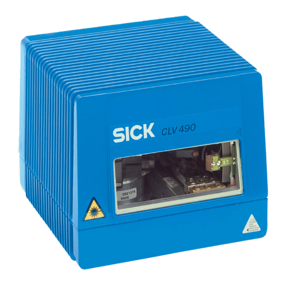
Blind hole thread M 6, 7 mm deep, › "I/O" connector, for securing the device 15-pin D Sub HD socket Design of the Fig. 3-1: CLV 490 © SICK AG · Division Auto Ident · Germany · All rights reserved 8 008 796/0000/25-06-2002... -
Page 25: Method Of Operation
System, warning, and error messages help you to configure the device and to locate the source of errors during startup and reading mode. 8 008 796/0000/25-06-2002 © SICK AG · Division Auto Ident · Germany · All rights reserved... -
Page 26: Autofocus Function
Optimum focus position: measured distance plus offset for maximum Depth of field (DOF) Fig. 3-3: Optimization of the depth of field for the object © SICK AG · Division Auto Ident · Germany · All rights reserved 8 008 796/0000/25-06-2002... -
Page 27: Event-Controlled Dynamic Focus Control
• Oscillating with variable deflection amplitude per distance configuration • One-Shot: one-off, defined deflection per reading pulse (forward and return phase) 8 008 796/0000/25-06-2002 © SICK AG · Division Auto Ident · Germany · All rights reserved... -
Page 28: Additional Components
If the optional external parameter memory is connected, the LEDs also indicate whether the memory was successfully accessed. Device Ready Sensor Read Result Data Fig. 3-5: LEDs © SICK AG · Division Auto Ident · Germany · All rights reserved 8 008 796/0000/25-06-2002... -
Page 29: Table 3-2: Meaning Of Leds: Clv Without External Parameter Memory
"CLV-Setup" program. Download to CLV! TART WITH THE INTERNAL ARAMETERS EVICE ONFIGURATION Table 3-2: Meaning of LEDs: CLV without external parameter memory 8 008 796/0000/25-06-2002 © SICK AG · Division Auto Ident · Germany · All rights reserved... -
Page 30: Table 3-3: Meaning Of Leds: Clv With External Parameter Memory
Page 8-5 2) Stops blinking when you switch from Reading mode to Parameterization mode Table 3-3: Meaning of LEDs: CLV with external parameter memory 3-10 © SICK AG · Division Auto Ident · Germany · All rights reserved 8 008 796/0000/25-06-2002... - Page 31 • Blinks bright/dark alternately, in the frequency with which the scan line is (partially) Show CP-limits Sensor Green masked out Table 3-3: Meaning of LEDs: CLV with external parameter memory 3-11 8 008 796/0000/25-06-2002 © SICK AG · Division Auto Ident · Germany · All rights reserved...
- Page 32 Chapter 3 Product description Operating Instructions CLV 490 Bar Code Scanner Notes 3-12 © SICK AG · Division Auto Ident · Germany · All rights reserved 8 008 796/0000/25-06-2002...
-
Page 33: Installation
CLV) 4.2.3 Required auxiliary parts • 2 screws M 6 for securing the SICK mounting bracket to the base. The screw length depends on the wall thickness of the base. • Set of laser warning labels (if necessary) •... -
Page 34: Replacing The Laser Warning Label
The CLV can be mounted at a maximum distance of 1 200 m from the host without a connection to the SICK network or a bus. In practice, however, the distance depends on the physical configuration of the host interface and the data transfer rate (see... -
Page 35: Mounting Accessories
Line scanner: Mounting possibilities of the CLV The dimensions of the mounting brackets are shown in Chapter 10.14 Dimensioned draw- ings of the accessories, Page 10-75 8 008 796/0000/25-06-2002 © SICK AG · Division Auto Ident · Germany · All rights reserved... -
Page 36: Distance Between The Clv And The Bar Code
Due to the V-principle of beam deflection, the reading field height (for evaluating the useful length of the scan line) depends on the readling distance. © SICK AG · Division Auto Ident · Germany · All rights reserved 8 008 796/0000/25-06-2002... -
Page 37: Table 4-1: Permissible Reading Angles Between The Scan Line And Bar Code
The device can only be flush-mounted with the conveyor belt with limited de- flection ranges. Otherwise, the device must also be mounted at an angle of 15° to ensure that the deflection ranges are symmetric. 8 008 796/0000/25-06-2002 © SICK AG · Division Auto Ident · Germany · All rights reserved... -
Page 38: Count Direction Of The Code Position Cp And Code Angle Cw
If this is required to evaluate the result in the host, the values can be included in the separator of the output string using the "CLV-Setup" program. © SICK AG · Division Auto Ident · Germany · All rights reserved 8 008 796/0000/25-06-2002... -
Page 39: Mounting And Adjusting The Device
6. Screw the screws M 6 through the bracket into the blind hole threads of the CLV. 7. Tighten the screws slightly. 8. Adjust the CLV as described below. 8 008 796/0000/25-06-2002 © SICK AG · Division Auto Ident · Germany · All rights reserved... -
Page 40: Adjusting The Clv
– in "One-Shot" mode, the CLV also positions the scan line under the angle CW = 50 – in "Set Position" mode, the scan line’s selected position remains unchanged. © SICK AG · Division Auto Ident · Germany · All rights reserved 8 008 796/0000/25-06-2002... -
Page 41: Adjusting Mode
(code position CP = 50), is located at the center of the bar code, or at the center of the field for all codes if several bar codes are used. 8 008 796/0000/25-06-2002 © SICK AG · Division Auto Ident · Germany · All rights reserved... -
Page 42: Mounting The External Components
Bar code at the start of the object (Top view) b < a b < a Fig. 4-10: Line scanner: mounting example for the external reading pulse sensor 4-10 © SICK AG · Division Auto Ident · Germany · All rights reserved 8 008 796/0000/25-06-2002... - Page 43 The CLV operates with the "Sensor" switching input as an external trigger source. The reading pulse starts when the input is energized (high). 4-11 8 008 796/0000/25-06-2002 © SICK AG · Division Auto Ident · Germany · All rights reserved...
-
Page 44: Mounting The Sensors For Detecting The Object Distance
Chapter 4.4.2 Mounting the external reading pulse sensor, Page 4-10. Default: Focus position F 1 up to F 8 = 1 200 mm. 4-12 © SICK AG · Division Auto Ident · Germany · All rights reserved 8 008 796/0000/25-06-2002... -
Page 45: Dismantling The Device
When removing the device from service for the last time, please dispose of it in an environmentally-friendly manner, as described in Chapter 7.3 Disposal, Page 7-2. 4-13 8 008 796/0000/25-06-2002 © SICK AG · Division Auto Ident · Germany · All rights reserved... - Page 46 Installation Chapter 4 Operating Instructions CLV 490 Bar Code Scanner Notes 4-14 © SICK AG · Division Auto Ident · Germany · All rights reserved 8 008 796/0000/25-06-2002...
-
Page 47: Electrical Installation
Electrical installation Installation sequence • Connect the CLV to a SICK Connection Module from the series AMV/S, BMV/BMH 10 or BMS 20, or using a customer-specific wiring configuration • Connect the data and function interfaces of the CLV in the module •... -
Page 48: Electrical Connections And Cables
Table 5-2: Cables for connecting the CLV Chapter 10.13.4 Cables, external parameter memo- For technical data on the cables, see ries and plug cover, Page 10-73. © SICK AG · Division Auto Ident · Germany · All rights reserved 8 008 796/0000/25-06-2002... -
Page 49: Connections/Cables For The Amv/S Connection Module
The module can be used to establish a connection to the host (point-to-point) or integrate the device in a SICK network or daisy-chain configuration (pass-through or master/slave configuration). The module is available in several variants... -
Page 50: Connections/Cables For The Bus Connection Modules Bmv 10 And Bms 20
With two 15-pin D Sub HD connections (pin assignment identical to that of the CLV terminals), no. 2 020 307 • With a connector cover, no. 2 021 689 © SICK AG · Division Auto Ident · Germany · All rights reserved 8 008 796/0000/25-06-2002... -
Page 51: Connections/Cables For The Ip 65 Connector Cover (Connection To Amv 100/200 Or Bmv 10)
CLV, the temperature must not drop below max. –40 °C. Recommendation Use the external parameter memory no. 2 020 267 (open cable ends) for connecting the device to non-Sick Power packs/wiring configurations. 8 008 796/0000/25-06-2002 © SICK AG · Division Auto Ident · Germany · All rights reserved... -
Page 52: Connector Pin Assignment
1) Pin 1 is jumpered with Pin 1 of the "Host/Term" connection in the CLV Table 5-4: Pin assignment of the 15-pin D Sub HD "I/O" socket © SICK AG · Division Auto Ident · Germany · All rights reserved 8 008 796/0000/25-06-2002... -
Page 53: External Parameter Memory
1) Pin 1 is jumpered with Pin 1 of the Host/Term connection in the CLV Table 5-6: Pin assignment of the 15-pin D Sub HD "I/O" cable socket 8 008 796/0000/25-06-2002 © SICK AG · Division Auto Ident · Germany · All rights reserved... -
Page 54: Preparations For Electrical Installation
Power-up delay The selected device number (default: 1) affects the power-up delay of the device. This is useful if a large number of CLVs (e. g. in the SICK network) are to be supplied from one power source. Table 5-9 contains a list of the available intervals. -
Page 55: Non-Sick Power Supply Unit/Connections Without The Connection Module5-9
5.4.3 Non-SICK Power supply unit/connections without the Connection Module Power output If an non-Sick Power supply unit is used instead of the AMS 60, it must be capable of providing the following voltage and power values: • For CLV without heater: 18 ... 30 V DC, min. 20 W continuous power output •... - Page 56 2 020 981. Connect the free cable ends accordingly. The wire Table 5-12 Table 5-13. color assignments are shown in CLV with heater: Available on request. 5-10 © SICK AG · Division Auto Ident · Germany · All rights reserved 8 008 796/0000/25-06-2002...
-
Page 57: Table 5-12: Wire Color Assignment Of Cable 1 For External Parameter Memory No. 2 020 981
1) Pin 1 is jumpered with Pin 1 of the "Host/Term" connection in the CLV Table 5-13: Wire color assignment of cable 2 for external parameter memory no. 2 020 981 5-11 8 008 796/0000/25-06-2002 © SICK AG · Division Auto Ident · Germany · All rights reserved... - Page 58 Grey-brown TxD (RS 232), Host – – Shield Orange Table 5-15: Wire color assignment cable 2 for connector cover no. 2 021 267 5-12 © SICK AG · Division Auto Ident · Germany · All rights reserved 8 008 796/0000/25-06-2002...
-
Page 59: Electrical Installation Procedure
5.5.3 Connecting the supply voltage a) SICK AMV/S and BMV 10 Connection Modules If the CLV is powered via the SICK Connection Modules, the supply voltage does not have to be wired separately. Connecting the CLV without external parameter memory: 1. -
Page 60: Connecting The Host Interface
SICK (start character: STX, stop character: ETX, no request for repeat: none, timeout: 50 ms) Table 5-16: Communication parameters for the host interface (default setting) 5-14 © SICK AG · Division Auto Ident · Germany · All rights reserved 8 008 796/0000/25-06-2002... -
Page 61: Connecting The Can Interface
Instructions for the connection and for configuration of the CLV to use the device in the SICK-specific CAN Scanner Network or in a CANopen network see the Operating Instruc- tions “Application of the CAN interface“ (no. 8 009 180, English edition). -
Page 62: Connecting The Switching Inputs
For connecting the host interface via the AMV/S 60 Connection Module, see the Operating Instructions for the "AMV/S 60 Connection Module" (no. 8 008 296). Note An external pulse is not required for Percentage Evaluation mode. 5-16 © SICK AG · Division Auto Ident · Germany · All rights reserved 8 008 796/0000/25-06-2002... -
Page 63: Table 5-18: Pin And Terminal Assignment For "In 0
For connecting the host interface via the AMV/S 60 Connection Module, see the Operating Instructions for the "AMV/S 60 Connection Module" (no. 8 008 296). 5-17 8 008 796/0000/25-06-2002 © SICK AG · Division Auto Ident · Germany · All rights reserved... -
Page 64: Table 5-19: Characteristic Data Of The "In 0
1) 1 = energized (active); 0 = deenergized (inactive) 2) Distance configuration (DC): data record for focus position Table 5-20: Dynamic focus control: switching inputs/distance configuration assignment table 5-18 © SICK AG · Division Auto Ident · Germany · All rights reserved 8 008 796/0000/25-06-2002... -
Page 65: Connecting The "Result 1 Result 4" Switching Outputs
AMV/S 60. Table 5-23, Page 5-20 contains the characteristic data for these outputs. The four outputs have the same characteristic data. 5-19 8 008 796/0000/25-06-2002 © SICK AG · Division Auto Ident · Germany · All rights reserved... -
Page 66: Table 5-22: Pin And Terminal Assignment For "Result 1
To check the switching functions using a high-impedance digital voltmeter, connect a load to the outputs to prevent incorrect voltage values/switching statuses from being displayed. 5-20 © SICK AG · Division Auto Ident · Germany · All rights reserved 8 008 796/0000/25-06-2002... -
Page 67: Operation
CLV-Setup prints out the complete set of default settings in the form of a table. The header contains the company and user names that were entered during the CLV-Setup installation routine. 8 008 796/0000/25-06-2002 © SICK AG · Division Auto Ident · Germany · All rights reserved... -
Page 68: Default Settings Of The Line Scanner Clv 490 (All Variants)
Fixed position 50 CW (corresponds to an angle of deflection of 105°) Table 6-2: Extract: Default parameter settings of the line scanner with oscillating mirror CLV 490 © SICK AG · Division Auto Ident · Germany · All rights reserved... -
Page 69: Quick Start
Fig. 6-1: Bar code pattern (Code 39; module width 0.35 mm; Print ratio 2:1) 8 008 796/0000/25-06-2002 © SICK AG · Division Auto Ident · Germany · All rights reserved... -
Page 70: Switching The Clv With External Parameter Memory Connected On For The First Time With The Factory Default Settings
Switching the CLV with external parameter memory connected on for the first time with the factory default settings 1. Connect the CLV to the SICK AMV/S 60 Connection Module via the external parameter memory no. 2 020 307 using the two cables. -
Page 71: Configuring (Parameterization) The Clv
If the "CLV-Setup" program does not recognize parameters transferred during the upload, it outputs a warning message. Unknown parameters can be edited in the E tab by XTRAS 8 008 796/0000/25-06-2002 © SICK AG · Division Auto Ident · Germany · All rights reserved... -
Page 72: Function Of The Tabs In Clv-Setup (Overview)
• Trigger source for the focus control (if event-controlled) • Adjustment to bar code quality caracteristics and relative module width © SICK AG · Division Auto Ident · Germany · All rights reserved 8 008 796/0000/25-06-2002... - Page 73 Test string function • Output sequence and sort criteria for reading more than one bar code per reading pulse • Format mask and its structure 8 008 796/0000/25-06-2002 © SICK AG · Division Auto Ident · Germany · All rights reserved...
-
Page 74: Parameterizing Example
• Specifying the terminal interface function (auxiliary interface) • Indicating the source of the parameter set for starting up (only with external parameter memory) © SICK AG · Division Auto Ident · Germany · All rights reserved 8 008 796/0000/25-06-2002... -
Page 75: Table 6-4: Guide: Parameterizing Autofocus Mode (Part 1)
The minimum and maximum values for the active evaluation range of the scan line (M ) can be checked in the S mode. OSITION LIMITS Chapter 6.5.5 Show CP-limits, Page 6-26. 8 008 796/0000/25-06-2002 © SICK AG · Division Auto Ident · Germany · All rights reserved... -
Page 76: Table 6-5: Guide: Parameterizing The Autofocus Function (Part 2)
"Limit values: scan angle limitation" and "Limit value: autofocus space". Scan angle Autofocus space limitation Fig. 6-2: Narrowing the visible range using limit values 6-10 © SICK AG · Division Auto Ident · Germany · All rights reserved 8 008 796/0000/25-06-2002... -
Page 77: Assignment Table
The minimum and maximum values for the active evaluation range of the scan line (M ) can be checked in the S mode. OSITION LIMITS Chapter 6.5.5 Show CP-limits, Page 6-26. 6-11 8 008 796/0000/25-06-2002 © SICK AG · Division Auto Ident · Germany · All rights reserved... -
Page 78: Table 6-7: Guide: Parameterizing Oscillating Mirror Functions
7. Choose activity of oscillating mode Ö SCILLATING IRROR acitve SCILLATING IRROR – continuous – during reading interval Table 6-7: Guide: Parameterizing oscillating mirror functions 6-12 © SICK AG · Division Auto Ident · Germany · All rights reserved 8 008 796/0000/25-06-2002... -
Page 79: Fig. 6-3: Oscillating Mirror: "Oscillating With Fixed Amplitude" Mode
Fig. 6-4, Page 6-14 illustrates this mode when a bar code is read from above. 6-13 8 008 796/0000/25-06-2002 © SICK AG · Division Auto Ident · Germany · All rights reserved... -
Page 80: Fig. 6-4: Oscillating Mirror: "Oscillating With Variable Amplitude" Mode
Possible trigger sources for One-Shot: • "IN 3" or "IN 4" switching input • Command string (via serial interface) • Reading interval 6-14 © SICK AG · Division Auto Ident · Germany · All rights reserved 8 008 796/0000/25-06-2002... -
Page 81: Fig. 6-5: One-Shot: Object Tracking (Bar Code Read From Front)
Line scanner Reduced reading range through One-Shot function Line scanner with oscillating mirror Fig. 6-5: One-Shot: Object tracking (bar code read from front) 6-15 8 008 796/0000/25-06-2002 © SICK AG · Division Auto Ident · Germany · All rights reserved... -
Page 82: Table 6-8: Guide: Parameterizing The Reading Trigger Source
(The laser diode is always active, indepen- – Click (deactivate) the control box I NTERVAL dent of the pulse duration) ACTIVE Table 6-9: Guide: Parameterizing the laser timeout 6-16 © SICK AG · Division Auto Ident · Germany · All rights reserved 8 008 796/0000/25-06-2002... -
Page 83: Table 6-10: Guide: Settings For Evaluating Identical Bar Codes
Ö • Physical interface Data Format OST INTERFACE Ö Ö • Communication parameters Data Format NTERFACE Ö Ö • Protocol Interface Protocol NTERFACE 6-17 8 008 796/0000/25-06-2002 © SICK AG · Division Auto Ident · Germany · All rights reserved... - Page 84 UXILIARY NTERFACE g) Defining the start option for accessing the parameter set Ö • On the D choose S EVICE ONFIGURATION TART WITH 6-18 © SICK AG · Division Auto Ident · Germany · All rights reserved 8 008 796/0000/25-06-2002...
-
Page 85: Operating Modes And Outputing The Reading Result
In the Reading mode the CLV deflects (by default) the scan line about the position CW = 50 at a frequency of 1 Hz and a maximum angle of ±20°. 50 CW corresponds to an angle of deflection of 105°. 6-19 8 008 796/0000/25-06-2002 © SICK AG · Division Auto Ident · Germany · All rights reserved... -
Page 86: Fig. 6-6: Clv-Setup: Displaying The Reading Result In The Terminal Emulator
Good Read, and Fig. 6-8, Page 6-21 for No Read. Fig. 6-6: CLV-Setup: Displaying the reading result in the Terminal Emulator 6-20 © SICK AG · Division Auto Ident · Germany · All rights reserved 8 008 796/0000/25-06-2002... -
Page 87: Fig. 6-7: Reading Result Of The Terminal Interface: Structure For Good Read
Chapter 6.5.8 Monitor Host Interface, Page 6-29 describes the procedure for this and the structure of the reading result in the default setting. 6-21 8 008 796/0000/25-06-2002 © SICK AG · Division Auto Ident · Germany · All rights reserved... -
Page 88: Percentage Evaluation
"One-Shot" mode, the CLV positions the scan line under the angle CW = 50 as well. – in ”Fixed position” mode, however the scan line’s selected position remains unchanged. 6-22 © SICK AG · Division Auto Ident · Germany · All rights reserved 8 008 796/0000/25-06-2002... -
Page 89: Fig. 6-9: Clv-Setup: Displaying The Percentage Evaluation In The Terminal Emulator
The output format of the reading result is the same as that of the Reading mode. Fig. 6-7, Page 6-21 explains the structure and function of the reading diagnosis data. 6-23 8 008 796/0000/25-06-2002 © SICK AG · Division Auto Ident · Germany · All rights reserved... -
Page 90: Adjusting Mode
3. Choose R to exit the Adjusting mode. EADING The CLV returns to the Reading mode and the "Device Ready" LED lights up. 6-24 © SICK AG · Division Auto Ident · Germany · All rights reserved 8 008 796/0000/25-06-2002... -
Page 91: Background Teach-In
CLV must not contain any objects. In this mode, the CLV does not output any reading results. The Background teach-in function can be started as a device function via CLV 490 (interac- tively), or press the [F2] key. -
Page 92: Show Cp-Limits
Show CP-limits can be called up via V in the menu bar, as a device function via CLV 490 (interactively), or via the Terminal Emulator. 6-26 © SICK AG · Division Auto Ident · Germany · All rights reserved 8 008 796/0000/25-06-2002... -
Page 93: Fig. 6-12: Appearance Of Scan Line In The "Show Cp-Limits" Mode
In the Reading mode, the CLV does not actually blank the scan line visually, but instead takes the values specified for the restricted evaluation range into account when the data contents are decoded. 6-27 8 008 796/0000/25-06-2002 © SICK AG · Division Auto Ident · Germany · All rights reserved... -
Page 94: Displaying And Editing Operating Data
In the default setting, the CLV only outputs the error status ST in the separator via the host interface. 6-28 © SICK AG · Division Auto Ident · Germany · All rights reserved 8 008 796/0000/25-06-2002... -
Page 95: Monitor Host Interface
4. Present the bar code pattern from 5. Click the SW-T button or press [F8]. RIGGER CLV-Setup outputs the reading result in the Terminal Emulator. Example: "O 0123412345". 6-29 8 008 796/0000/25-06-2002 © SICK AG · Division Auto Ident · Germany · All rights reserved... -
Page 96: Fig. 6-14: Clv-Setup: Displaying The Reading Result Of The Host Interface In The Terminal Emulator With Direction Identifier At The Beginning (In This Case: O = Output)
ERMANENT The CLV outputs the selected elements in the data output string of the host interface with the next reading result. 6-30 © SICK AG · Division Auto Ident · Germany · All rights reserved 8 008 796/0000/25-06-2002... -
Page 97: Auxiliary Input
Chapter 8.3.1 CLV without external parameter memory, Page 8-2, lists the error keys together with the associated corrective measures. 6-31 8 008 796/0000/25-06-2002 © SICK AG · Division Auto Ident · Germany · All rights reserved... -
Page 98: Executing Clv Functions Interactively
Show CP-limits has been started. Fig. 6-16: CLV-Setup: Dialog box for executing Show limits 6-32 © SICK AG · Division Auto Ident · Germany · All rights reserved 8 008 796/0000/25-06-2002... -
Page 99: Clv Messages
Chapter 8.3.1 CLV without external parameter memory, Page 8-2 lists the messages in alphabetical order together with the associated corrective measures. 6-33 8 008 796/0000/25-06-2002 © SICK AG · Division Auto Ident · Germany · All rights reserved... -
Page 100: Switching Off The Clv
3. Make the necessary entries in the dialog box and confirm these. CLV-Setup prints out the current configuration file in the form of a table. 6-34 © SICK AG · Division Auto Ident · Germany · All rights reserved 8 008 796/0000/25-06-2002... -
Page 101: Maintenance
If necessary, clean the LEDs on the rear of the device. Clean here Front reading window Side reading window Fig. 7-1: Cleaning the reading window 8 008 796/0000/25-06-2002 © SICK AG · Division Auto Ident · Germany · All rights reserved... -
Page 102: Maintenance
5. Send the chassis and cover (aluminium) to be recycled. 6. Send the electronic modules for disposal as problem waste. At present, SICK AG does not accept any unusable or irreparable devices. © SICK AG · Division Auto Ident · Germany · All rights reserved 8 008 796/0000/25-06-2002... -
Page 103: Troubleshooting
CLV outputs the message: Laser safety timeout on the terminal interface. The reading interval must be terminated by resetting the trigger signal. The laser diode is activated again by the next reading trigger. 8 008 796/0000/25-06-2002 © SICK AG · Division Auto Ident · Germany · All rights reserved... -
Page 104: Error Messages
It therefore loads the default set- ting of the distance configura- tions. Table 8-1: Error messages output on the terminal interface © SICK AG · Division Auto Ident · Germany · All rights reserved 8 008 796/0000/25-06-2002... - Page 105 Device fault. Contact the SICK Service depart- oscillating mirror or cannot ini- ment. tialize the mirror. Table 8-1: Error messages output on the terminal interface 8 008 796/0000/25-06-2002 © SICK AG · Division Auto Ident · Germany · All rights reserved...
- Page 106 Download any changes to the • RK 512: without reaction tele- CLV! gram Table 8-1: Error messages output on the terminal interface © SICK AG · Division Auto Ident · Germany · All rights reserved 8 008 796/0000/25-06-2002...
-
Page 107: Led Error Messages For The External Parameter Memory
2) Flashing stops when the device switches from Reading mode to Parameter mode (e. g. during download from CLV-Setup). Table 8-2: LED error messages for access to the external parameter memory 8 008 796/0000/25-06-2002 © SICK AG · Division Auto Ident · Germany · All rights reserved... - Page 108 CLV briefly and monitor the "Device Ready" LED as described under 1. Table 8-2: LED error messages for access to the external parameter memory © SICK AG · Division Auto Ident · Germany · All rights reserved 8 008 796/0000/25-06-2002...
-
Page 109: Messages For Errors Accessing The External Parameter Memory
It has loaded the internal para- meter set to its RAM. Table 8-3: Messages for problems accessing the external parameter memory 8 008 796/0000/25-06-2002 © SICK AG · Division Auto Ident · Germany · All rights reserved... - Page 110 Table 8-2, (Error type: 101, 114) set with tolerated errors to its Page 8-5 RAM. Table 8-3: Messages for problems accessing the external parameter memory © SICK AG · Division Auto Ident · Germany · All rights reserved 8 008 796/0000/25-06-2002...
-
Page 111: St Error Status In The Reading Result Of A Bar Code
C32 bar codes (output as 9- digit decimal values). Table 8-4: Meaning of the ST error status in the reading result 8 008 796/0000/25-06-2002 © SICK AG · Division Auto Ident · Germany · All rights reserved... -
Page 112: General Malfunctions: Clv Not Ready
Table 6-9, Page 6-16, current reading pulse (trigger mode: sensor input/serial interface) Table 8-5: Troubleshooting: restoring operation (Reading mode) 8-10 © SICK AG · Division Auto Ident · Germany · All rights reserved 8 008 796/0000/25-06-2002... -
Page 113: Malfunctions In Reading Mode: Reading Trigger Errors
DIT READING RIGGER section: is generat- ND OF EADING NTERVAL ed by Trigger Source selected? Table 8-6: Troubleshooting: reading trigger errors in Reading mode 8-11 8 008 796/0000/25-06-2002 © SICK AG · Division Auto Ident · Germany · All rights reserved... -
Page 114: Malfunctions In Reading Mode: Result Output Errors
D section: ONFIGURATION ECODER choose SMART decoder. Download all changes to CLV! Table 8-7: Troubleshooting: result output errors in Reading mode 8-12 © SICK AG · Division Auto Ident · Germany · All rights reserved 8 008 796/0000/25-06-2002... - Page 115 "Device Ready" LED light up? If not, contact the SICK Service department. Table 8-7: Troubleshooting: result output errors in Reading mode 8-13 8 008 796/0000/25-06-2002 © SICK AG · Division Auto Ident · Germany · All rights reserved...
-
Page 116: Malfunctions In Reading Mode: Errors In The Result Status Output
(default setting: Match 1) switching outputs are not outputting any pulses Table 8-8: Troubleshooting: errors in the result status output in Reading mode 8-14 © SICK AG · Division Auto Ident · Germany · All rights reserved 8 008 796/0000/25-06-2002... -
Page 117: Malfunctions In Reading Mode: Oscillating Mirror Errors
CLV may be defective. The CLV does not contain any components that can be repaired by the user. Please contact your local SICK office or subsidiary. The telephone and fax numbers are li- sted on the back page of this manual. - Page 118 Chapter 8 Troubleshooting Operating Instructions CLV 490 Bar Code Scanner Notes 8-16 © SICK AG · Division Auto Ident · Germany · All rights reserved 8 008 796/0000/25-06-2002...
-
Page 119: Technical Data
1) Default setting, in Reading mode with the "Switching input sensor" and "Serial interface pulse" types. 2) Reading interval: time window generated internally for evaluating the code. Table 9-1: Technical specifications of the CLV 490-0010/-2010/-6010 8 008 796/0000/25-06-2002 © SICK AG · Division Auto Ident · Germany · All rights reserved... -
Page 120: Data Sheet Clv 490-1010/-3010/-7010 Bar Code Scanner
(for power supply) Weight approx. 1.5 kg –35 ... +35 °C/–20 ... +70 °C Ambient operating/storage temperature Table 9-3: Technical specifications of the CLV 490-0011/-2011/-6011 © SICK AG · Division Auto Ident · Germany · All rights reserved 8 008 796/0000/25-06-2002... -
Page 121: Data Sheet Clv 490-1011/-3011/-7011 Bar Code Scanner
33.4 43.3 Device Ready Sensor Read Result Data All values in mm Fig. 9-1: Dimensions of the CLV 490 line scanner, front reading window 8 008 796/0000/25-06-2002 © SICK AG · Division Auto Ident · Germany · All rights reserved... -
Page 122: Line Scanner With Oscillating Mirror (Without/With Heater)
6 mm deep CLV490 50° All values in mm Fig. 9-2: Dimensions of the CLV 490: line scanner with oscillating mirror, side reading window © SICK AG · Division Auto Ident · Germany · All rights reserved 8 008 796/0000/25-06-2002... -
Page 123: Appendix
> 75 % Table 10-1: Reading conditions for specification diagrams Note The min. and max. reading distances are measured radially by the CLV. 10-1 8 008 796/0000/25-06-2002 © SICK AG · Division Auto Ident · Germany · All rights reserved... -
Page 124: Overview Of Diagrams
CLV 490-1010/-1011 Standard density L.s. with osci. mirror Reading field height/resolution as a function of reading 10-9 distance CLV 490-1010/-1011 Standard density L.s. with osci. mirror Min. and max. reading distance (DOF) for 0.35 mm/40° 10-10 CLV 490-1010/-1011 Standard density L.s. with osci. mirror Min. and max. reading distance (DOF) for 0.35 mm/50°... -
Page 125: Standard Density: Reading Performance Data Of Line Scanner
10.2.3 Standard density: Reading performance data of line scanner Fig. 10-1: CLV 490-0010/-0011 (Standard density): Reading field height as a function of the reading distance and resolution 10-3 8 008 796/0000/25-06-2002 © SICK AG · Division Auto Ident · Germany · All rights reserved... -
Page 126: Clv 490-0010/-0011
Fig. 10-6, Page 10-8 Fig. 10-2: CLV 490-0010/-0011 (Standard density): Min. and Max. reading distance (measured radially) as a function of the focus position at a resolution of 0.35 mm and an aperture angle of α = 40° 10-4 ©... - Page 127 Fig. 10-6, Page 10-8 Fig. 10-3: CLV 490-0010/-0011 (Standard density): Min. and Max. reading distance (measured radially) as a function of the focus position at a resolution of 0.35 mm and an aperture angle of α = 56° 10-5 8 008 796/0000/25-06-2002 ©...
- Page 128 Fig. 10-6, Page 10-8 Fig. 10-4: CLV 490-0010/-0011 (Standard density): Min. and Max. reading distance (measured radially) as a function of the focus position at a resolution of 0.50 mm and an aperture angle of α = 40° 10-6 ©...
- Page 129 Fig. 10-6, Page 10-8 Fig. 10-5: CLV 490-0010/-0011 (Standard density): Min. and Max. reading distance (measured radially) as a function of the focus position at a resolution of 0.50 mm and an aperture angle of α = 56° 10-7 8 008 796/0000/25-06-2002 ©...
-
Page 130: Fig. 10-6: Characteristics Field Clv 490-0010/-0011: Scanning Frequency As A Function Of The Reading Distance And Resolution
0.50 mm Table 10-1, Page 10-1 Fig. 10-6: Characteristics field CLV 490-0010/-0011: Scanning frequency as a function of the reading distance and resolution 10-8 © SICK AG · Division Auto Ident · Germany · All rights reserved 8 008 796/0000/25-06-2002... -
Page 131: Standard Density: Reading Performance Data Of Line Scanner With Oscillating Mirror
Standard density: Reading performance data of line scanner with oscillating mirror Fig. 10-7: CLV 490-1010/-1011 (Standard density): Reading field height as a function of the reading distance and resolution 10-9 8 008 796/0000/25-06-2002 © SICK AG · Division Auto Ident · Germany · All rights reserved... -
Page 132: Fig. 10-8: Clv 490-1010/-1011 (Standard Density): Min. And Max. Reading
Fig. 10-12, Page 10-14 Fig. 10-8: CLV 490-1010/-1011 (Standard density): Min. and Max. reading distance (measured radially) as a function of the focus position at a resolution of 0.35 mm and an aperture angle of α = 40° 10-10 ©... -
Page 133: Fig. 10-9: Clv 490-1010/-1011 (Standard Density): Min. And Max. Reading
Fig. 10-12, Page 10-14 Fig. 10-9: CLV 490-1010/-1011 (Standard density): Min. and Max. reading distance (measured radially) as a function of the focus position at a resolution of 0.35 mm and an aperture angle of α = 50° 10-11 8 008 796/0000/25-06-2002 ©... -
Page 134: Fig. 10-10: Clv 490-1010/-1011 (Standard Density): Min. And Max. Reading
Fig. 10-12, Page 10-14 Fig. 10-10: CLV 490-1010/-1011 (Standard density): Min. and Max. reading distance (measured radially) as a function of the focus position at a resolution of 0.50 mm and an aperture angle of α = 40°... -
Page 135: Fig. 10-11: Clv 490-1010/-1011 (Standard Density): Min. And Max. Reading
Fig. 10-12, Page 10-14 Fig. 10-11: CLV 490-1010/-1011 (Standard density): Min. and Max. reading distance (measured radially) as a function of the focus position at a resolution of 0.50 mm and an aperture angle of α = 50°... -
Page 136: Fig. 10-12: Characteristics Field Clv 490-1010/-1011: Scanning Frequency As A Function Of The Reading Distance And Resolution
0.35 mm Table 10-1, Page 10-1 0.50 mm Fig. 10-12: Characteristics field CLV 490-1010/-1011: Scanning frequency as a function of the reading distance and resolution 10-14 © SICK AG · Division Auto Ident · Germany · All rights reserved 8 008 796/0000/25-06-2002... -
Page 137: Fig. 10-13: Clv 490-1010/-1011 (Standard Density): Deflection Range As A Function Of Reading Distance, Deflection Angle And Resolution
0.35 mm Reading conditions: Table 10-1, Page 10-1 0.50 mm Fig. 10-13: CLV 490-1010/-1011 (Standard density): deflection range as a function of reading distance, deflection angle and resolution 10-15 8 008 796/0000/25-06-2002 © SICK AG · Division Auto Ident · Germany · All rights reserved... -
Page 138: High Density: Reading Performance Data Of Line Scanner
10.2.5 High density: Reading performance data of line scanner Fig. 10-14: CLV 490-2010/-2011 (High density): Reading field height as a function of the reading distance and resolution 10-16 © SICK AG · Division Auto Ident · Germany · All rights reserved... -
Page 139: Fig. 10-15: Clv 490-2010/-2011 (High Density): Min. And Max. Reading
Table 10-18, Page 10-20 Fig. 10-15: CLV 490-2010/-2011 (High density): Min. and Max. reading distance (measured radially) as a function of the focus position at a resolution of 0.25 mm and an aperture angle of α = 40°... -
Page 140: Fig. 10-16: Clv 490-2010/-2011 (High Density): Min. And Max. Reading
Table 10-18, Page 10-20 Fig. 10-16: CLV 490-2010/-2011 (High density): Min. and Max. reading distance (measured radially) as a function of the focus position at a resolution of 0.35 mm and an aperture angle of α = 40°... -
Page 141: Fig. 10-17: Clv 490-2010/-2011 (High Density): Min. And Max. Reading
Table 10-18, Page 10-20 Fig. 10-17: CLV 490-2010/-2011 (High density): Min. and Max. reading distance (measured radially) as a function of the focus position at a resolution of 0.35 mm and an aperture angle of α = 56°... -
Page 142: Fig. 10-18: Characteristics Field Clv 490-2010/-2011: Scanning Frequency As A Function Of The Reading Distance And Resolution
0.25 mm Table 10-1, Page 10-1 0.30 mm Fig. 10-18: Characteristics field CLV 490-2010/-2011: Scanning frequency as a function of the reading distance and resolution 10-20 © SICK AG · Division Auto Ident · Germany · All rights reserved 8 008 796/0000/25-06-2002... -
Page 143: High Density: Reading Performance Data Line Scanner With Oscillating Mirror
CLV 490 Bar Code Scanner 10.2.6 High density: Reading performance data line scanner with oscillating mirror Fig. 10-19: CLV 490-3010/-3011 (High density): Reading field height as a function of the reading distance and resolution 10-21 8 008 796/0000/25-06-2002 © SICK AG · Division Auto Ident · Germany · All rights reserved... -
Page 144: Fig. 10-20: Clv 490-3010/-3011: (High Density) Min. And Max. Reading
Table 10-23, Page 10-25 Fig. 10-20: CLV 490-3010/-3011: (High density) Min. and Max. reading distance (measured radially) as a function of the focus position at a resolution of 0.25 mm and an aperture angle of α = 40°... -
Page 145: Fig. 10-21: Clv 490-3010/-3011 (High Density): Min. And Max. Reading
Table 10-23, Page 10-25 Fig. 10-21: CLV 490-3010/-3011 (High density): Min. and Max. reading distance (measured radially) as a function of the focus position at a resolution of 0.35 mm and an aperture angle of α = 40°... -
Page 146: Fig. 10-22: Clv 490-3010/-3011 (High Density): Min. And Max. Reading
Table 10-23, Page 10-25 Fig. 10-22: CLV 490-3010/-3011 (High density): Min. and Max. reading distance (measured radially) as a function of the focus position at a resolution of 0.35 mm and an aperture angle of α = 50°... -
Page 147: Fig. 10-23: Characteristics Field Clv 490-3010/-3011: Scanning Frequency As A Function Of The Reading Distance And Resolution
0.25 mm Table 10-1, Page 10-1 0.30 mm Fig. 10-23: Characteristics field CLV 490-3010/-3011: Scanning frequency as a function of the reading distance and resolution 10-25 8 008 796/0000/25-06-2002 © SICK AG · Division Auto Ident · Germany · All rights reserved... -
Page 148: Fig. 10-24: Clv 490-3010/-3011: Deflection Range As A Function Of Reading Distance, Deflection Angle And Resolution
Reading conditions: 0.30 mm Table 10-1, Page 10-1 Fig. 10-24: CLV 490-3010/-3011: Deflection range as a function of reading distance, deflection angle and resolution 10-26 © SICK AG · Division Auto Ident · Germany · All rights reserved 8 008 796/0000/25-06-2002... -
Page 149: Low Density: Reading Performance Data Of Line Scanner
CLV 490 Bar Code Scanner 10.2.7 Low density: Reading performance data of line scanner Fig. 10-25: CLV 490-6010/-6011 (Low density): Reading field height as a function of the reading distance and the tilt at a resolution of 0.5 mm 10-27 8 008 796/0000/25-06-2002 ©... -
Page 150: Fig. 10-26: Clv 490-6010/-6011 (Low Density): Min. And Max. Reading
Table 10-28, Page 10-30 Fig. 10-26: CLV 490-6010/-6011 (Low density): Min. and Max. reading distance (measured radially) as a function of the focus position at a resolution of 0.5 mm and an aperture angle of α = 40°... -
Page 151: Fig. 10-27: Clv 490-6010/-6011 (Low Density): Min. And Max. Reading
Table 10-28, Page 10-30 Fig. 10-27: CLV 490-6010/-6011 (Low density): Min. and Max. reading distance (measured radially) as a function of the focus position at a resolution of 0.5 mm and an aperture angle of α = 60°... -
Page 152: Fig. 10-28: Characteristics Field Clv 490-6010/-6011: Scanning Frequency As A Function Of The Reading Distance And Resolution
Reading conditions: Table 10-1, Page 10-1 0.50 mm Fig. 10-28: Characteristics field CLV 490-6010/-6011: Scanning frequency as a function of the reading distance and resolution 10-30 © SICK AG · Division Auto Ident · Germany · All rights reserved 8 008 796/0000/25-06-2002... -
Page 153: Low Density: Reading Performance Data Of Line Scanner With Oscillating Mirror
10.2.8 Low density: Reading performance data of line scanner with oscillating mirror Fig. 10-29: CLV 490-7010/-7011 (Low density): Reading field height as a function of the reading distance and tilt at a resolution of 0.5 mm 10-31 8 008 796/0000/25-06-2002... -
Page 154: Fig. 10-30: Characteristics Field Clv 490-7010/-7011: Scanning Frequency As A Function Of The Reading Distance And Resolution
Resolution: Table 10-1, Page 10-1 0.50 mm Fig. 10-30: Characteristics field CLV 490-7010/-7011: Scanning frequency as a function of the reading distance and resolution 10-32 © SICK AG · Division Auto Ident · Germany · All rights reserved 8 008 796/0000/25-06-2002... -
Page 155: Fig. 10-31: Clv 490-7010/-7011: Deflection Range As A Function Of Reading Distance, Deflection Angle And Tilt At A Resolution Of 0.5 Mm
–30° ... +30° Reading conditions: Table 10-1, Page 10-1 –15° ...+15° Fig. 10-31: CLV 490-7010/-7011: Deflection range as a function of reading distance, deflection angle and tilt at a resolution of 0.5 mm 10-33 8 008 796/0000/25-06-2002 © SICK AG · Division Auto Ident · Germany · All rights reserved... -
Page 156: Installing And Operating The External Parameter Memory
The "Device Ready" and "Read Result" LEDs indicate whether the external me- mory was accessed successfully. The CLV also outputs plain-text messages for troubles- hooting purposes on the terminal interface. 10-34 © SICK AG · Division Auto Ident · Germany · All rights reserved 8 008 796/0000/25-06-2002... -
Page 157: Installation And Electrical Connection
The "Device Ready" LED blinks for approx. 10 s and then lights up constantly. The data in the CLV is lost when the device is switched off. 10-35 8 008 796/0000/25-06-2002 © SICK AG · Division Auto Ident · Germany · All rights reserved... -
Page 158: Switching On The Device For The First Time
Adjust the parameter set in the external parameter memory as described in Chapter 6.4.1 Configuring the CLV via the user interface of CLV-Setup, Page 6-5 10-36 © SICK AG · Division Auto Ident · Germany · All rights reserved 8 008 796/0000/25-06-2002... -
Page 159: Meaning Of The Leds
CLV to CLV-Setup and then download it again to the CLV with the P ERMANENT storage option. When asked to do so, adjust the external memory again. 10-37 8 008 796/0000/25-06-2002 © SICK AG · Division Auto Ident · Germany · All rights reserved... -
Page 160: Optional Heating
[°C] The temperature enables the operating voltage for the CLV internally Time [min] Fig. 10-35: CLV with heater: temperature curve inside the housing 10-38 © SICK AG · Division Auto Ident · Germany · All rights reserved 8 008 796/0000/25-06-2002... -
Page 161: Electrical Installation
If the CLV with integrated heater is used outdoors, it should be installed in a protective hou- sing to prevent the front window from being damaged by rain, snow, or dust. The housing also acts as a wind protector. 10-39 8 008 796/0000/25-06-2002 © SICK AG · Division Auto Ident · Germany · All rights reserved... -
Page 162: System Messages
"internal parameters copied to external memory" successfully copied to the external parameter memory. Table 10-6: Additional CLV system messages for the connected parameter memory 10-40 © SICK AG · Division Auto Ident · Germany · All rights reserved 8 008 796/0000/25-06-2002... -
Page 163: Installing And Operating The "Clv-Setup" Program
6. Then confirm the installation message by clicking OK. 7. Restart the PC. The Windows DLL files are possibly updated. The "CLV-Setup" program and CLV-Setup Help are installed and ready. 10-41 8 008 796/0000/25-06-2002 © SICK AG · Division Auto Ident · Germany · All rights reserved... - Page 164 The new version of CLV-Setup is installed. The configuration files of the old version can be used again. 10-42 © SICK AG · Division Auto Ident · Germany · All rights reserved 8 008 796/0000/25-06-2002...
-
Page 165: Starting Clv-Setup
The default setting the first time the device is used is the CLV 41x. The software then loads the internal device description for this CLV type and displays the default values on the tabs. 10-43 8 008 796/0000/25-06-2002 © SICK AG · Division Auto Ident · Germany · All rights reserved... -
Page 166: Fig. 10-36: Clv-Setup: Result Display Of The Autobaud Detect Function
CLV-Setup then uploads the current parameter set from the RAM of the CLV to its database and displays the values on the tabs. You can edit the current parameter set on the tabs. 10-44 © SICK AG · Division Auto Ident · Germany · All rights reserved 8 008 796/0000/25-06-2002... -
Page 167: User Interface
CLV, the PC’s interface parameter display, error display field (system errors), device specification field and status display for the connection to the CLV. Fig. 10-37: User interface of the "CLV-Setup" software 10-45 8 008 796/0000/25-06-2002 © SICK AG · Division Auto Ident · Germany · All rights reserved... -
Page 168: Functions
Automatic storage confirmation prompt when changes are made to the configuration file • Wizards for individual functions • CLV 490 only: Aligment check to calculate the required setting for angles • CLV 490 only: Background analysis • Set switches for starting the program (in the "CLVmain.ini" file) •... -
Page 169: Transferring Parameter Sets Between Clv-Setup And The Clv
If the program detects an error, it outputs a warning and enters the problem parameter/ value in the window on the E tab. XTRAS 10-47 8 008 796/0000/25-06-2002 © SICK AG · Division Auto Ident · Germany · All rights reserved... -
Page 170: Log File In The Terminal Emulator
In this way, for example, you can prevent CLV-Setup from attempting to establish a connection when a CLV is not connected. 10.6.11 The CLV Assistant The CLV assistant is not suitable for parameterizing the CLV 490. 10-48 © SICK AG · Division Auto Ident · Germany · All rights reserved 8 008 796/0000/25-06-2002... -
Page 171: Configuring A Clv With Command Strings
, and press the <Return> key. The command is sent to the CLV. The CLV answers with an echo if the command was syntactically correct (in most cases). 10-49 8 008 796/0000/25-06-2002 © SICK AG · Division Auto Ident · Germany · All rights reserved... - Page 172 The parameter values directly changed with command strings in the CLV are registered and shown only after the parameter set is uploaded from the CLV. A list of command strings, is available on request. 10-50 © SICK AG · Division Auto Ident · Germany · All rights reserved 8 008 796/0000/25-06-2002...
-
Page 173: Calculating Parameter Values For Setting The Clv
Code window s = l – l Fig. 10-40: Line scanner: calculating the number of scans for fence-type bar code arrangements 10-51 8 008 796/0000/25-06-2002 © SICK AG · Division Auto Ident · Germany · All rights reserved... -
Page 174: Fig. 10-41: Line Scanner With Oscillating Mirror: Calculating The Number Of Scans For Fence-Type Bar Code Positioning
---------------------- 1.26 Hz n = 476 Fig. 10-41: Line scanner with oscillating mirror: calculating the number of scans for fence-type bar code positioning 10-52 © SICK AG · Division Auto Ident · Germany · All rights reserved 8 008 796/0000/25-06-2002... -
Page 175: Calculating The Start Position And Mirror Speed For The Forward And Return Phase Of The One-Shot Function
Check the theoretically calculated values on site and adapt them if required. Fig. 10-42: One-Shot: Line scanner with oscillating mirror: calculating the number of scans for fence-type bar code positioning 10-53 8 008 796/0000/25-06-2002 © SICK AG · Division Auto Ident · Germany · All rights reserved... -
Page 176: Calculating The Necessary Bar Code Distance If Several Bar Codes Are Read On Each Object
Rule of thumb: the blank zone should surround the bar code completely! Fig. 10-43: Required distance between the bar codes on an object 10-54 © SICK AG · Division Auto Ident · Germany · All rights reserved 8 008 796/0000/25-06-2002... -
Page 177: Tables
Table 10-8: Formulas for calculating the code length of a bar code 10-55 8 008 796/0000/25-06-2002 © SICK AG · Division Auto Ident · Germany · All rights reserved... -
Page 178: 10.10 Discussion Of A Parameterization Example
Parameterization of the CLV based on the factory defaults Requirements: • Testing the application for feasability with the CLV 490 before buying, with the help of the SMART calculation sheet (service provided by SICK) • Choice of CLV type: here standard density line scanner (CLV 490-0010) •... -
Page 179: 10.10.4 Important Clarifications
5. Connect the pulse photoelectric switch to the AMV/S 60 connection module Chapter 5.5.7 Connecting the switching inputs, Page 5-16). (see 6. Turn on the supply voltage to the CLV. 10-57 8 008 796/0000/25-06-2002 © SICK AG · Division Auto Ident · Germany · All rights reserved... -
Page 180: 10.10.6 Parameterize The Clv With The "Clv-Setup" Program
10-59): DJUSTMENTS – Preference of focus distance: Fix focus position: 1 200 mm (approx. 100 mm above the packet with the smallest height) 10-58 © SICK AG · Division Auto Ident · Germany · All rights reserved 8 008 796/0000/25-06-2002... -
Page 181: Fig. 10-46: Parameterization Example: "Edit Auto Focus/Adjustments" Dialog Window
Level of conveyor (Z1): 50 mm Maximum scanning height (Z2): 800 mm Fig. 10-47: Parameterization example: "Edit Auto Focus/Limits" dialog window 10-59 8 008 796/0000/25-06-2002 © SICK AG · Division Auto Ident · Germany · All rights reserved... -
Page 182: Fig. 10-48: Parameterization Example: "Edit Auto Focus/Optimizations" Dialog Window
Confirm the dialog window by clicking "OK". 2. Setting up the autofocus function (Part 2): D EVICE ONFIGURATION Fig. 10-49: Parameterization example: Buttons on the "Device Configuration" tab 10-60 © SICK AG · Division Auto Ident · Germany · All rights reserved 8 008 796/0000/25-06-2002... -
Page 183: Fig. 10-50: Parameterization Example: "Edit Scanner Position/Angles" Dialog Window
– Y coordinate: 300 mm (The middle of the CLV to the left edge of the conveyor belt in the direction of convoyer belt) – Z coordinate: 1 400 mm (Height of the CLV above the conveyor belt) 10-61 8 008 796/0000/25-06-2002 © SICK AG · Division Auto Ident · Germany · All rights reserved... -
Page 184: Fig. 10-51: Parameterization Example: "Edit Scanner Position/Coordinates" Dialog Window
In the Output on Good read group click the option End of label. Fig. 10-52: Parameterization example: Settings on the "Device Configuration" tab ¾ Confirm the dialog box with "OK". 10-62 © SICK AG · Division Auto Ident · Germany · All rights reserved 8 008 796/0000/25-06-2002... -
Page 185: Fig. 10-53: Parameterization Example: Settings On The "Code Configuration" Tab
- Transmit Check Digit: activate - Transmit Leading Zero: activate Fig. 10-54: Parameterization example: "2/5 Interleaved" tab ¾ Confirm dialog box with ”OK”. 10-63 8 008 796/0000/25-06-2002 © SICK AG · Division Auto Ident · Germany · All rights reserved... -
Page 186: 10.10.7 Testing The Application
Check the reading rate with the Terminal Emulator in the CLV-Setup while an application is running. The reading rate should be > 90%. 10-64 © SICK AG · Division Auto Ident · Germany · All rights reserved 8 008 796/0000/25-06-2002... -
Page 187: 10.11 Special Applications And Procedures
ARAMETERS 6. Confirm the dialog box by choosing the T storage option. EMPORARY The terminal interface then operates temporarily in "Auxiliary input" mode. 10-65 8 008 796/0000/25-06-2002 © SICK AG · Division Auto Ident · Germany · All rights reserved... -
Page 188: Fig. 10-58: Clv-Setup: Auxiliary Input On The Terminal Emulator
6. Once the active reading pulse has ended, the CLV sends the data received from the PC to the host via the host interface. Fig. 10-58: CLV-Setup: auxiliary input on the Terminal Emulator 10-66 © SICK AG · Division Auto Ident · Germany · All rights reserved 8 008 796/0000/25-06-2002... -
Page 189: Table 10-9: Communication Parameters On The Terminal/Pc For The Auxiliary Input
Once the active reading pulse has ended, the CLV sends the data received from the PC to the host via the host interface. If you are using the ST 1100 decoder from SICK, for example, set the communication para- meters and data output as shown in Table 10-10. -
Page 190: Daisy-Chain Configuration (Data Forwarding Or Master/Slave Arrangement)
See Operating Instructions "Application of the CAN interface" (no. 8 009 180). 10.11.9 Integration in an OPS reading system See Operating Instructions "Omni Tracking System OTS 400" (no. 8 008 869). 10-68 © SICK AG · Division Auto Ident · Germany · All rights reserved 8 008 796/0000/25-06-2002... -
Page 191: Replacing A Clv (Copying The Parameter Set)
The new device, however, outputs an error message in CLV-Setup for each of these parame- ters/values when the parameter set is downloaded. 10-69 8 008 796/0000/25-06-2002 © SICK AG · Division Auto Ident · Germany · All rights reserved... -
Page 192: 10.12.2 Importing The Parameter Set From The External Memory
10-70 © SICK AG · Division Auto Ident · Germany · All rights reserved 8 008 796/0000/25-06-2002... -
Page 193: 10.13 Accessories
20 ... 30 V DC 6 020 893 BMH 10-0111 Bus module for connection of one CLV 490 to Profibus DP; with terminal screws, a 9-pin D-sub bus socket, no housing, for top-hat-rail installation, enclosure rating max. IP 20, operating voltage... - Page 194 TCP/IP communication, data transmission rate 10 MBit/s. For the CLV 490 with 1x 15-pin D Sub HD device socket/plug. With a 8-pin RJ-45 bus socket, ter- minal strips (signal distributors) for wiring the RS 232 data interface and the functional interfaces, internal 9-pin D Sub "Service"...
-
Page 195: 10.13.4 Cables, External Parameter Memories And Plug Cover
Table 10-14: Accessories: cables and connector covers for the CLV without heater Note Other cable lengths/types for CLV without heater available on request. 10-73 8 008 796/0000/25-06-2002 © SICK AG · Division Auto Ident · Germany · All rights reserved... -
Page 196: 10.13.5 Plug-In Connections
Table 10-16: Accessories: plug-in connections 10.13.6 Reading pulse generators The SICK catalog "SENSICK Sensors for Automation" (no. 8 006 530) contains a large sel- ection of photoelectric switches and photoelectric proximity switches as well as the asso- ciated accessories (brackets, connection cables) 10.13.7 Network controller... -
Page 197: 10.14 Dimensioned Drawings Of The Accessories
– 1 x threaded pin M 8 x 16 mm No. 2 013 824 Fig. 10-61: Front view of quick clamping device No. 2 016 110 with angle braket No. 2 0130824 10-75 8 008 796/0000/25-06-2002 © SICK AG · Division Auto Ident · Germany · All rights reserved... -
Page 198: 10.15 Supplementary Documentation
BMV/bus module BMH 10 8 008 869 "Omni Tracking System OTS 400" Description of the integration of the CLV 490 in an omnidirectional OPS Operating Instructions reading system 8 009 180 "Application of the CAN Interface"... -
Page 199: 10.16 Glossary
CLV parameters and their permissible values and can be launched directly from CLV-Setup in an HTML browser, such as Netscape Navigator , or I-ViewPro supplied with the program. 10-77 8 008 796/0000/25-06-2002 © SICK AG · Division Auto Ident · Germany · All rights reserved... - Page 200 CW = 50 at each side (corresponds to a deflection angle of 105 ). Also referred to as oscillating amplitude. The maximum deflection range is set in 10-78 © SICK AG · Division Auto Ident · Germany · All rights reserved 8 008 796/0000/25-06-2002...
- Page 201 The entry for the host interface is made in the separator of the Ö data output string and must be enabled using the parameters (enabled by default). 10-79 8 008 796/0000/25-06-2002 © SICK AG · Division Auto Ident · Germany · All rights reserved...
- Page 202 One-Shot). Master/slave configuration Special arrangement for connecting up to max. 10 SICK bar code scanners in the CAN scan- ner network to one reading station (e. g. left/right read). Thanks to the master, the entire net- work appears as one device to the host.
- Page 203 Only output on the host interface if enabled on the D TRING in the "CLV-Setup" program. The error status ST is output in the separator by default. 10-81 8 008 796/0000/25-06-2002 © SICK AG · Division Auto Ident · Germany · All rights reserved...
- Page 204 Special, high performance network of max. 31 CLVs with high data transfer rates on the RS 485 interface. The CLVs are coordinated (polling) and connected to the host via the CLX 200 Network Controller. 10-82 © SICK AG · Division Auto Ident · Germany · All rights reserved 8 008 796/0000/25-06-2002...
- Page 205 (U ). Displays the current parameter values PLOAD ARAMETER on the tabs. Prerequisite for modifying the current parameter set. 10-83 8 008 796/0000/25-06-2002 © SICK AG · Division Auto Ident · Germany · All rights reserved...
- Page 206 Appendix Chapter 10 Operating Instructions CLV 490 Bar Code Scanner User interface Windows-based PC software "CLV-Setup" for operating and configuring the CLV. 10-84 © SICK AG · Division Auto Ident · Germany · All rights reserved 8 008 796/0000/25-06-2002...
-
Page 207: 10.17 Copy Of The Ec Declaration Of Conformity
CLV 490 Bar Code Scanner 10.17 Copy of the EC Declaration of Conformity Fig. 10-62: Reproduction of the declaration of conformity (Page 1, reduced in size) 10-85 8 008 796/0000/25-06-2002 © SICK AG · Division Auto Ident · Germany · All rights reserved... -
Page 208: Fig. 10-63: Reproduction Of The Declaration Of Conformity (Page 2, Reduced In Size)
Appendix Chapter 10 Operating Instructions CLV 490 Bar Code Scanner Fig. 10-63: Reproduction of the declaration of conformity (Page 2, reduced in size) 10-86 © SICK AG · Division Auto Ident · Germany · All rights reserved 8 008 796/0000/25-06-2002... -
Page 209: 10.18 Index
- Function..................6-5 - Tabs.....................6-6 - Start Download............... 6-6 - Unknown parameters .............10-47 - Upload ..................6-5 Electrical installation ..............5-1 - User interface ..............10-45 10-87 8 008 796/0000/25-06-2002 © SICK AG · Division Auto Ident · Germany · All rights reserved... - Page 210 Intended use of CLV..............2-1 - Percentage evaluation ............6-22 Interbus-S .................. 10-68 - Reading mode ..............6-19 Interfaces of CLV - Show CP-limits..............6-26 - Functions................... 3-5 Oscillating mirror 10-88 © SICK AG · Division Auto Ident · Germany · All rights reserved 8 008 796/0000/25-06-2002...
- Page 211 - Low density, line scanner with osc. mirror ..... 10-32 - Parametrization ...............5-8 - Standard density, line scanner ........10-8 Profibus ..................10-68 - Standard density, line scanner with osc. mirror ... 10-14 10-89 8 008 796/0000/25-06-2002 © SICK AG · Division Auto Ident · Germany · All rights reserved...
- Page 212 - Max. cable length..............4-2 - Operating mode ..............6-28 Terminator..................6-30 Thread Blind hole - Dimensions ................4-3 - Position ..................3-4 Troubleshooting 10-90 © SICK AG · Division Auto Ident · Germany · All rights reserved 8 008 796/0000/25-06-2002...
-
Page 213: 10.19 Bar Code Example
Module width Module width Module width 0.35 mm 0.5 mm 1.0 mm Fig. 10-64: Scannable bar codes with various module widths (print ratio 2:1) 10-91 8 008 796/0000/25-06-2002 © SICK AG · Division Auto Ident · Germany · All rights reserved... - Page 214 I t a l y Phone +39 02-92 14 20 62 Representatives and agencies in +39 02-92 14 20 67 all major industrial countries. SICK AG · Division Auto Ident · Nimburger Straße 11 · 79276 Reute · Germany · www.sick.de...
Need help?
Do you have a question about the CLV 490 and is the answer not in the manual?
Questions and answers