Table of Contents
Advertisement
Advertisement
Table of Contents
Troubleshooting

Related Manuals for SICK CLV 420


Summary of Contents for SICK CLV 420
- Page 1 O P E R A T I N G I N S T R U C T I O N S CLV42x Bar Code Scanner Standard Line...
-
Page 2: Sick Ag · Division Auto Ident · Germany · All Rights Reserved
Microsoft Corporation in the USA and other countries. Latest manual version For the latest version of this manual (PDF), see www.sick.com. © SICK AG · Division Auto Ident · Germany · All rights reserved 8 009 981/O078/16-08-2004... - Page 3 Chapter 6.4 Configuration (parameterizing), Page 6-4 • Troubleshooting – Chapter 8 Troubleshooting, Page 8-1 • Finding information – Table of contents, Page – Index, Page 10-49 8 009 981/O078/16-08-2004 © SICK AG · Division Auto Ident · Germany · All rights reserved...
- Page 4 Copy the parameter set to the CLV permanently via download. 18. Save the parameter set as a "*.scl" configuration file in CLV Setup. The CLV contains application-specific settings and is ready for operation. © SICK AG · Division Auto Ident · Germany · All rights reserved 8 009 981/O078/16-08-2004...
-
Page 5: Table Of Contents
Installing the external reading pulse sensor .............. 4-9 4.4.3 Installing the polling reflector ..................4-10 Removing the device......................4-12 Electrical connection ....................5-1 Overview of the connection sequence ................5-1 8 009 981/O078/16-08-2004 © SICK AG · Division Auto Ident · Germany · All rights reserved... - Page 6 Overview of errors and malfunctions which could occur ..........8-1 8.1.1 Installation errors ........................8-1 8.1.2 Electrical connection errors ....................8-1 8.1.3 Parameterization errors......................8-1 8.1.4 Malfunctions during operation..................8-1 Monitoring errors and malfunctions ..................8-1 Error messages..........................8-2 © SICK AG · Division Auto Ident · Germany · All rights reserved 8 009 981/O078/16-08-2004...
- Page 7 Connection to Profibus DP..................10-34 10.9.4 Connection to DeviceNet.................... 10-34 10.9.5 Connection to Ethernet TCP/IP ................. 10-34 10.9.6 Buildung up a CAN Scanner Network..............10-34 8 009 981/O078/16-08-2004 © SICK AG · Division Auto Ident · Germany · All rights reserved...
- Page 8 10.13 Supplementary documentation ..................10-41 10.13.1 CLV Connect (from version 1.9) ................10-41 10.14 Glossary ............................10-42 10.15 EC Declaration of Conformity....................10-48 10.16 Index............................10-49 10.17 Bar code samples.........................10-53 © SICK AG · Division Auto Ident · Germany · All rights reserved 8 009 981/O078/16-08-2004...
- Page 9 Troubleshooting: reading pulse errors in reading mode........8-6 Table 8-5: Troubleshooting: result output errors in reading mode........8-7 Table 8-6: Troubleshooting: errors in the result status output in reading mode .....8-9 8 009 981/O078/16-08-2004 © SICK AG · Division Auto Ident · Germany · All rights reserved...
- Page 10 Table 10-10: Accessories: Extensions for connection modules ..........10-38 Table 10-11: Accessories: cables and plug-in connections ............10-39 Table 10-12: Accessories: reading pulse generators (polling reflectors)......10-39 Table 10-13: Supplementary documentation................10-41 I-10 © SICK AG · Division Auto Ident · Germany · All rights reserved 8 009 981/O078/16-08-2004...
- Page 11 CLV Setup: entering commands in the terminal emulator ......10-23 Fig. 10-9: Line scanner: calculating the number of scans for ladder-type bar code arrangements....................10-24 I-11 8 009 981/O078/16-08-2004 © SICK AG · Division Auto Ident · Germany · All rights reserved...
- Page 12 Copy of the Declaration of Conformity, Page 1 (scaled down)....10-48 Fig. 10-17: Scannable bar codes with various module widths (print ratio 2:1) ...10-53 I-12 © SICK AG · Division Auto Ident · Germany · All rights reserved 8 009 981/O078/16-08-2004...
-
Page 13: Notes On This Document
For further information on the design of the bar code scanner or on bar code technology in general, please contact the Auto Ident division at SICK AG. Internet address: www.sick.com. 8 009 981/O078/16-08-2004 © SICK AG · Division Auto Ident · Germany · All rights reserved... -
Page 14: Symbols Used
An action must be performed. This symbol identifies single-step instructions. Instructions consisting of several steps are numbered consecutively. Here you select a function of the user interface of CLV Setup. © SICK AG · Division Auto Ident · Germany · All rights reserved 8 009 981/O078/16-08-2004... -
Page 15: Safety Information
The CLV transfers the data content of the decoded bar codes via its host interface to a host for further processing. Any warranty claims vis-à-vis SICK AG will be rendered invalid if the device is used for any other purpose or if changes are made to the device, including any made during the installation and electrical connection procedures. -
Page 16: General Safety Instructions And Protection Measures
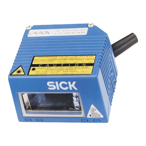
3-5). The additional laser warnings in English applicable to the USA are positioned on the back side of the attachment of the device and at the back end on the wide side. © SICK AG · Division Auto Ident · Germany · All rights reserved 8 009 981/O078/16-08-2004... -
Page 17: Fig. 2-1: Laser Warning Labels Found On The Clv
Read“, in reading mode, the laser diode is constantly activated. In the "reflector polling" trigger mode the laser diode is switched on for each 20th scan. 8 009 981/O078/16-08-2004 © SICK AG · Division Auto Ident · Germany · All rights reserved... -
Page 18: Quick Stop And Quick Restart
2.5.1 Power requirements The power requirements are particularly low: • the CLV 420/421/422 line/raster scanners have a max. power consumption of 3.5 W The value is given for devices with disconnected switching outputs. 2.5.2 Disposal after final decommissioning Always dispose of unusable or irreparable devices in a manner that is not harmful to the environment and in accordance with the applicable national waste disposal regulations. -
Page 19: Product Description
Line scanner with 105° angle attachment, high density CLV 422-3010 1 022 621 Raster scanner with 105° angle attachment, high density Table 3-1: Variants of the CLV 42x 8 009 981/O078/16-08-2004 © SICK AG · Division Auto Ident · Germany · All rights reserved... -
Page 20: System Requirements
– CDM 420-0001 (no. 1 025 362) for 10 to 30 V DC, enclosure rating max. IP 65 – or – Alternatively, a non-SICK power supply unit with a voltage output of 10 to 30 V DC (functional extra-low voltage pursuant to IEC 364-4-41) and at least 4 W power output. -
Page 21: Product Features And Functions (Overview)
Operating modes: • Reading mode • Percentage evaluation - for assessing the quality of the reads • AutoSetup • Special functions for system installation 8 009 981/O078/16-08-2004 © SICK AG · Division Auto Ident · Germany · All rights reserved... - Page 22 Serial terminal interface (RS 232) as auxiliary data interface with special diagnosis functions • CAN interface for integration in the SICK CAN scanner network or a CANopen network • 2 switching inputs for external reading pulse and special function (e.g. teach-in of match code) •...
-
Page 23: View Of Line/Raster Scanner Devices
LEDs (status indicators) integrated angle attachment, with 105° light reflection Front reading window Side reading window Fig. 3-1: CLV42x line/raster scanner with/without 105° angle attachment 8 009 981/O078/16-08-2004 © SICK AG · Division Auto Ident · Germany · All rights reserved... -
Page 24: Method Of Operation
"CLV Setup" software or via the host/terminal interface and command strings. System messages, warnings and error messages help you with configuration and with locating the source of errors during startup and in reading mode. © SICK AG · Division Auto Ident · Germany · All rights reserved 8 009 981/O078/16-08-2004... -
Page 25: Scan Procedure Variants
3-3) are located on the rear of the device. Table 3-2 shows the meaning of the LED indicators in the different operating modes/functions. Fig. 3-3: LED indicators 8 009 981/O078/16-08-2004 © SICK AG · Division Auto Ident · Germany · All rights reserved... -
Page 26: Table 3-2: Meaning Of The Led Indicators
• blinks bright/dark alternately, in the frequency with which the scan line is orange Show CP-limits Laser On partially masked out Table 3-2: Meaning of the LED indicators © SICK AG · Division Auto Ident · Germany · All rights reserved 8 009 981/O078/16-08-2004... -
Page 27: Function Of The Beeper
5. Confirm the dialog box by selecting the P save option. ERMANENT The CLV operates the beeper with the values selected for the result status indication and volume. 8 009 981/O078/16-08-2004 © SICK AG · Division Auto Ident · Germany · All rights reserved... - Page 28 Chapter 3 Product description Operating Instructions CLV 42x bar code scanner Notes 3-10 © SICK AG · Division Auto Ident · Germany · All rights reserved 8 009 981/O078/16-08-2004...
-
Page 29: Installation
Polling reflectors for automatic internal generation of the reading pulse trigger 4.2.3 Laying out other required materials • Two M4 screws for securing the SICK mounting bracket to the base. The screw length depends on the wall thickness of the base. • Set of laser warning labels (if necessary) •... -
Page 30: Replacing The Laser Warning Label
Distance between the CLV and the host The CLV can be installed without a connection to the SICK CAN Scanner Network or to a bus connection max. 1,200 m (3,936.96 ft) away from the host. The distance which can be achieved depends on the selected model of the host interface and the set data transfer rate, however. -
Page 31: Fig. 4-2: Location Of The Securing Threads On The Clv
The slots in the brackets allow a turning freedom of 15° for the fine adjustment of the CLV. Fig. 4-3: Installation example: mounting the CLV with mounting bracket no. 2 020 077 8 009 981/O078/16-08-2004 © SICK AG · Division Auto Ident · Germany · All rights reserved... -
Page 32: Distance Between The Clv And The Bar Code
105° angle attachment. Due to the V-principle of beam deflection, the reading field height (for evaluating the useful length of the scan line) depends on the reading distance. © SICK AG · Division Auto Ident · Germany · All rights reserved 8 009 981/O078/16-08-2004... -
Page 33: Table 4-1: Permissible Reading Angles Between The Scan Line And Bar Code
The laser beam from the line/raster scanner with angle attachment is emitted at an angle of 105° with respect to the housing. Depending on the application, the device can also be installed flush with the conveyor belt. 8 009 981/O078/16-08-2004 © SICK AG · Division Auto Ident · Germany · All rights reserved... -
Page 34: Count Direction Of The Code Position Cp
The CLV outputs the CP value for each bar code in the reading result via the host interface. The values are displayed as a 3-digit number in the associated “Code- Info/Separator“ block. © SICK AG · Division Auto Ident · Germany · All rights reserved 8 009 981/O078/16-08-2004... -
Page 35: Installing And Adjusting The Device
Once the CLV has started, it outputs a tone to indicate that the self-test was successfully completed. Shortly afterwards, it outputs two tones to indicate that it has assumed Reading mode. The "Device Ready" LED lights up. 8 009 981/O078/16-08-2004 © SICK AG · Division Auto Ident · Germany · All rights reserved... -
Page 36: Auxiliary Functions For Adjustment
CP = 50 CP = 0 Fig. 4-9: Line scanner: appearance of the scan line in the "adjusting mode" operating mode © SICK AG · Division Auto Ident · Germany · All rights reserved 8 009 981/O078/16-08-2004... -
Page 37: Installing External Components
Bar code in the middle or at the end of the moved object b < a b < a Fig. 4-10: Line scanner: installation example for the external reading pulse sensor 8 009 981/O078/16-08-2004 © SICK AG · Division Auto Ident · Germany · All rights reserved... -
Page 38: Installing The Polling Reflector
(Fig. 4-11). Table 4-2 lists the permissible range values for the polling reflectors. The pulse type is not selected in the default setting. 4-10 © SICK AG · Division Auto Ident · Germany · All rights reserved 8 009 981/O078/16-08-2004... -
Page 39: Table 4-2: Permissible Range Values For The Polling Reflectors
1. Connect the CLV to the CDB 420 or CDM 420 connection module and switch on the power supply to the module (see Chapter 5.5.3 Connecting the power supply, Page 5-5). 4-11 8 009 981/O078/16-08-2004 © SICK AG · Division Auto Ident · Germany · All rights reserved... -
Page 40: Removing The Device
When removing the device from service for the last time, please dispose of it in an environmentally-friendly manner, as described in Chapter 7.3 Disposal, Page 7-2. 4-12 © SICK AG · Division Auto Ident · Germany · All rights reserved 8 009 981/O078/16-08-2004... -
Page 41: Electrical Connection
(distribution function) and the power supply. The module can be used to establish a connection to the host (point-to-point) or to integrate the device in a SICK CAN Scanner Network. The CDM 420 additionally supports the CLV for connecting to a field bus system via an optional module (gateway) Fig. -
Page 42: Connector Pin Assignment
“Manuals & Software“ CD, which is included in the scope of delivery of the ICR. The software can also be downloaded from the SICK home page (www.sick.de) at “Service& Support/ Downloadpool“. It can be called up using a standard HTML browser (e. g. Internet... -
Page 43: Preparations For Electrical Connection
Power-up delay The selected device number (default setting: 1) affects the power-up delay of the device. This is useful if a large number of CLVs (e. g. in the SICK CAN Scanner Network) are supplied from one power source. Table 5-3 contains a list of the available intervals. -
Page 44: Non-Sick Power Pack/Connections Without The Sick Connection Module
Non-SICK power pack/connections without the SICK connection module If a non-SICK power supply unit is used instead of the CDB 420 or CDM 420, it must provide a functional extra-low voltage in accordance with the standard IEC 364-4-41 and a continuous power output of at least 4 W. -
Page 45: Connecting The Power Supply
Connect the host interface on the CLV to the host using shielded cables (EMC requirements). Ensure that the maximum cable lengths are not exceeded (Table 5-2, Page 5-3). 8 009 981/O078/16-08-2004 © SICK AG · Division Auto Ident · Germany · All rights reserved... -
Page 46: Connecting The Can Interface
5.5.5 Connecting the CAN interface For information on the connection and parameterization of the CLV for use in a SICK scanner network or in a CANopen network, see the Operating Instructions "Application of the CAN interface" (no. 8 009 180, English version). -
Page 47: Connecting The Pc
Fig. 5-3: Connections of the terminal interface 1. Switch off the PC and power supply to the SICK connection module. 2. Connect the PC to the internal, 9-pin ”Aux" plug of the connection module. Use a 3-core RS 232 data cable (null modem cable) for this purpose, e. g. -
Page 48: Connecting The "Sensor 1" Switching Input
• Conveyor increment input • External trigger source for end of the reading interval • Trigger source for switching over the dynamical reading configuration © SICK AG · Division Auto Ident · Germany · All rights reserved 8 009 981/O078/16-08-2004... -
Page 49: Connecting The "Result 1" And "Result 2" Switching Outputs
Table 5-7 describes the characteristic data for the outputs. This data is identical for both outputs. Connect the outputs as shown in Fig. 5-6. 8 009 981/O078/16-08-2004 © SICK AG · Division Auto Ident · Germany · All rights reserved... -
Page 50: Table 5-7: Characteristic Data Of The "Result 1" And "Result 2" Switching Outputs
Recommendation To check the switching functions using a high-impedance digital voltmeter, power the outputs. This prevents incorrect voltage values/switching statuses from being displayed. 5-10 © SICK AG · Division Auto Ident · Germany · All rights reserved 8 009 981/O078/16-08-2004... -
Page 51: Operation
CLV Setup prints out all of the default settings in the form of a table. The header contains the company and user names that were entered during the CLV Setup installation routine. 8 009 981/O078/16-08-2004 © SICK AG · Division Auto Ident · Germany · All rights reserved... -
Page 52: Default Settings: Line/Raster Scanner Clv 42X
RS 232; 9,600 bd; 8 data bits; no parity; 1 stop bit (values cannot be changed) Function Reading diagnosis Table 6-1: Extract: Default parameter settings of the line/raster scanner CLV 42x © SICK AG · Division Auto Ident · Germany · All rights reserved 8 009 981/O078/16-08-2004... -
Page 53: Quick Start
6.3.1 Starting up the line/raster scanner with the factory default settings 1. Connect the CLV to the SICK CDB 420 or CDM 420 connection module. 2. Connect the reading pulse sensor (e.g. photoelectric switch, switch) to the "Sensor 1" switching input of the CLV via the CDB 420 or CDM 420. See Chapter 5.5.7 Connecting... -
Page 54: Configuration (Parameterizing)
("Download parameters of this view") will be temporarily loaded into the CLV’s memory (RAM). To finish the parametrization done by this way all parameters must be download again to the CLV with the "Permanent" option. © SICK AG · Division Auto Ident · Germany · All rights reserved 8 009 981/O078/16-08-2004... -
Page 55: Function Of Tabs In Clv Setup (Overview)
Source of the reading pulse • Output time of the reading result referred to the start of the reading pulse • Laser timeout • Encoder parameters 8 009 981/O078/16-08-2004 © SICK AG · Division Auto Ident · Germany · All rights reserved... - Page 56 CAN Interface This tab (and additional dialog boxes) are used to set the following: • Operating mode of the CAN interface • Data transfer rate © SICK AG · Division Auto Ident · Germany · All rights reserved 8 009 981/O078/16-08-2004...
-
Page 57: Parameterization Guide
ODELABEL UALITY Alternative: Enable Dynamic Reading Configuration EADING ONFIGURATION YNAMIC EADING ONFIGURATION ACTIVE • Limite evaluation range of scan line EADING ONFIGURATION OSITION section 8 009 981/O078/16-08-2004 © SICK AG · Division Auto Ident · Germany · All rights reserved... -
Page 58: Table 6-3: Guide: Parameterizing Reading Pulse Source
(laser diode is always active when pulsing, – Click (deactivate) the A checkbox CTIVE regardless of the pulse duration) Table 6-4: Guide: parameterizing laser timeout © SICK AG · Division Auto Ident · Germany · All rights reserved 8 009 981/O078/16-08-2004... -
Page 59: Table 6-5: Guide: Settings To Be Made For The Evaluation Of Identical Bar Codes
Arrangement in the data network section EVICE ONFIGURATION RRANGEMENT • Physical interface section NTERFACE ORMAT • Communication parameters section NTERFACE ORMAT • Protocol section NTERFACE NTERFACE ROTOCOL 8 009 981/O078/16-08-2004 © SICK AG · Division Auto Ident · Germany · All rights reserved... -
Page 60: Configuring The Clv With Autosetup
While AutoSetup is running, the CLV outputs the step-by-step changes made to the parameter values in the search mode and the determined diagnosis data via the terminal 6-10 © SICK AG · Division Auto Ident · Germany · All rights reserved 8 009 981/O078/16-08-2004... - Page 61 To begin with, it only overwrites the appropriate parameter values in the RAM. The CLV returns to reading mode. The "Device Ready" LED lights up. The R EADING 6-11 8 009 981/O078/16-08-2004 © SICK AG · Division Auto Ident · Germany · All rights reserved...
-
Page 62: Fig. 6-2: Clv Setup: Autosetup Displayed In The Terminal Emulator
"No valid code found" (no valid bar code found or reading quality less than 75 %) "Cancel AutoSetup" (AutoSetup terminates) – or – "More than one code found" "Cancel AutoSetup" (AutoSetup terminates) 6-12 © SICK AG · Division Auto Ident · Germany · All rights reserved 8 009 981/O078/16-08-2004... - Page 63 5. Check the reading quality in the terminal emulator. This should be between 70 and 100 %. 6-13 8 009 981/O078/16-08-2004 © SICK AG · Division Auto Ident · Germany · All rights reserved...
-
Page 64: Operating Modes And Outputting The Reading Result
The R can be called up by choosing V in the menu bar or via the terminal EADING emulator. 6-14 © SICK AG · Division Auto Ident · Germany · All rights reserved 8 009 981/O078/16-08-2004... -
Page 65: Fig. 6-3: Clv Setup: Output Of The Reading Result Of The Terminal Interface In Terminal Emulator
Fig. 6-3: CLV Setup: output of the reading result of the terminal interface in terminal emulator 6-15 8 009 981/O078/16-08-2004 © SICK AG · Division Auto Ident · Germany · All rights reserved... -
Page 66: Fig. 6-4: Reading Result Of The Terminal Interface: Structure For "Good Read
4. Perform a download to the CLV. To do so, click the S option again with the right mouse button and choose ERIAL NTERFACE 6-16 © SICK AG · Division Auto Ident · Germany · All rights reserved 8 009 981/O078/16-08-2004... -
Page 67: Percentage Evaluation
LED flashes five times per second if the reading quality is 70 % to 90 % – LED is lit continuously if the reading quality is > 90 % 6-17 8 009 981/O078/16-08-2004 © SICK AG · Division Auto Ident · Germany · All rights reserved... -
Page 68: Adjusting Mode
CP = 50 to position CP = 100. 3. Choose R to exit the Adjusting mode. EADING The CLV returns to reading mode. The "Device Ready" LED lights up. 6-18 © SICK AG · Division Auto Ident · Germany · All rights reserved 8 009 981/O078/16-08-2004... -
Page 69: Show Cp-Limits
In the reading mode, the CLV does not actually mask the scan line visually, but instead takes the values specified for the restricted evaluation range into account when the data contents are decoded. 6-19 8 009 981/O078/16-08-2004 © SICK AG · Division Auto Ident · Germany · All rights reserved... -
Page 70: Displaying And Editing Operating Data
3. Confirm the dialog box by selecting the P save option. ERMANENT The terminal interface is now set to the "Reading Diagnosis" mode. 6-20 © SICK AG · Division Auto Ident · Germany · All rights reserved 8 009 981/O078/16-08-2004... -
Page 71: Monitor Host Interface
Fig. 6-1, Page 6-3. 5. Click the SW-T button or press [F8]. RIGGER CLV Setup outputs the reading result in the terminal emulator. Example: „0123412345“. 6-21 8 009 981/O078/16-08-2004 © SICK AG · Division Auto Ident · Germany · All rights reserved... -
Page 72: Fig. 6-9: Clv Setup: Output Of The Reading Result Of The Host Interface In The Terminal Emulator At The Beginning (In This Case: O = Output)
6. Perform a download to the CLV. This is done by clicking in the toolbar. The D dialog box is displayed. OWNLOAD ARAMETER 6-22 © SICK AG · Division Auto Ident · Germany · All rights reserved 8 009 981/O078/16-08-2004... -
Page 73: Auxiliary Input
The CLV returns to reading mode. The "Device Ready" LED lights up. Fig. 6-10: CLV Setup: displaying the self-test result in the terminal emulator 6-23 8 009 981/O078/16-08-2004 © SICK AG · Division Auto Ident · Germany · All rights reserved... -
Page 74: Performing Device Functions Of The Clv In The Dialog Box
AutoSetup has been started. Fig. 6-11: CLV Setup: dialog box for AutoSetup execution 6-24 © SICK AG · Division Auto Ident · Germany · All rights reserved 8 009 981/O078/16-08-2004... -
Page 75: Clv Messages
Chapter 8.3 Error messages, Page 8-2 lists the messages in alphabetical order together with the associated corrective measures. 6-25 8 009 981/O078/16-08-2004 © SICK AG · Division Auto Ident · Germany · All rights reserved... -
Page 76: Switching Off The Clv
RINT 3. Edit the dialog box accordingly and confirm. CLV Setup prints out the current configuration file in the form of a table. 6-26 © SICK AG · Division Auto Ident · Germany · All rights reserved 8 009 981/O078/16-08-2004... -
Page 77: Maintenance
Fig. 7-1: Cleaning the reading window Note Don’t open the device. The producer warranty will be forfeited if the device is opened. 8 009 981/O078/16-08-2004 © SICK AG · Division Auto Ident · Germany · All rights reserved... -
Page 78: Maintenance
6. Send the electronic modules and connection cable for disposal as special waste. At present, SICK AG does not accept any unusable or irreparable devices. © SICK AG · Division Auto Ident · Germany · All rights reserved 8 009 981/O078/16-08-2004... -
Page 79: Troubleshooting
The reading pulse must be terminated by resetting the pulse signal. The laser diode is activated again by the next reading pulse. 8 009 981/O078/16-08-2004 © SICK AG · Division Auto Ident · Germany · All rights reserved... -
Page 80: Table 8-1: Error Message Output On The Terminal Interface
• Protocol timeout too long for the reading pulse frequency Table 8-1: Error message output on the terminal interface © SICK AG · Division Auto Ident · Germany · All rights reserved 8 009 981/O078/16-08-2004... - Page 81 Make sure that the bar code is not reach 75% located within the reading range of the CLV. Table 8-1: Error message output on the terminal interface (contd.) 8 009 981/O078/16-08-2004 © SICK AG · Division Auto Ident · Germany · All rights reserved...
-
Page 82: Error Status St In Read Result Of A Bar Code
6-digit C39 bar codes as C32 bar codes (output as 9-digit decimal values). Table 8-2: Meaning of the ST error status in the reading result © SICK AG · Division Auto Ident · Germany · All rights reserved 8 009 981/O078/16-08-2004... -
Page 83: Troubleshooting
CLV sensor input/serial interface) Setup user interface. See Chapter 6.4.3 Parameterization guide, Page 6-7. Table 8-3: Troubleshooting: restoring operation (reading mode) 8 009 981/O078/16-08-2004 © SICK AG · Division Auto Ident · Germany · All rights reserved... -
Page 84: Malfunctions In Reading Mode: Reading Pulse Errors
NTERVAL "Generated by Trigger Source" selected? • No sensor signal • See Malfunction 1, Remedy Table 8-4: Troubleshooting: reading pulse errors in reading mode © SICK AG · Division Auto Ident · Germany · All rights reserved 8 009 981/O078/16-08-2004... -
Page 85: Malfunctions In Reading Mode: Result Output Errors
In the CLV Setup program: check reading quality. Start P . See ERCENTAGE VALUATION Chapter 6.5.2 Percentage evaluation, Page 6-17. Table 8-5: Troubleshooting: result output errors in reading mode 8 009 981/O078/16-08-2004 © SICK AG · Division Auto Ident · Germany · All rights reserved... - Page 86 Choose the tab for the relevant code. Is Transmit Check Digit activated? Change if necessary. Download to CLV! Table 8-5: Troubleshooting: result output errors in reading mode (contd.) © SICK AG · Division Auto Ident · Germany · All rights reserved 8 009 981/O078/16-08-2004...
-
Page 87: Malfunctions In Reading Mode: Errors When Outputting The Result Status
• Clock the CLV accordingly and present the first profile bar code. Present the next bar code within 10 s, etc. Table 8-7: Troubleshooting: configuration errors (parameterization) 8 009 981/O078/16-08-2004 © SICK AG · Division Auto Ident · Germany · All rights reserved... -
Page 88: Sick Support
The telephone numbers and email addresses are listed on the back page of this manual. For addresses see also www.sick.com. Do not send the device to the SICK service without first contacting us. 8-10 © SICK AG · Division Auto Ident · Germany · All rights reserved... -
Page 89: Technical Data
1) in Reading mode with the "Switching input Sensor 1" and "Serial interface" pulse types 2) Reading interval: time window generated internally for evaluating the code Table 9-1: Technical specifications of the CLV 420/421/422 (line/raster scanner) 8 009 981/O078/16-08-2004 © SICK AG · Division Auto Ident · Germany · All rights reserved... - Page 90 3) The CLV 42x is UL certificated when a class 2 power supply according to UL 1310 is used. Table 9-1: Technical specifications of the CLV 420/421/422 (line/raster scanner) (contd.) © SICK AG · Division Auto Ident · Germany · All rights reserved 8 009 981/O078/16-08-2004...
-
Page 91: Clv Dimensional Drawings
Line/Raster scanner with front light emergence: Line/Raster scanner with side light emergence: All specifications in mm (in) Fig. 9-1: Dimensions of the CLV 42x line/raster scanner 8 009 981/O078/16-08-2004 © SICK AG · Division Auto Ident · Germany · All rights reserved... - Page 92 Chapter 9 Technical data Operating Instructions CLV 42x bar code scanner Notes © SICK AG · Division Auto Ident · Germany · All rights reserved 8 009 981/O078/16-08-2004...
-
Page 93: Appendix
15 mm (0.59 in) at 200 mm (7.88 in) reading distance Note Line/raster scanner with 105° angle attachment: the whole reading range shifts by 15 mm (0.59 in) towards the reading window. For the CLV 420 a corresponding reading field diagram is shown in Fig. 10-2. 10-1 8 009 981/O078/16-08-2004 ©... -
Page 94: Reading Field Diagram For Clv 420 Line/Raster Scanner (Front Reading Window)
General reading conditions: Table 10-1, Page 10-1 Scan frequency/reading distance characteristics: Fig. 10-5, Page 10-6 Fig. 10-1: CLV 420-0010/-1010: reading range (DOF) for line/raster scanner 10-2 © SICK AG · Division Auto Ident · Germany · All rights reserved 8 009 981/O078/16-08-2004... -
Page 95: Reading Field Diagram For Clv 420 Line/Raster Scanner With 105° Angle Attachment (Lateral Reading Window)
Table 10-1, Page 10-1 Scan frequency/reading distance characteristics: Fig. 10-5, Page 10-6 Fig. 10-2: CLV 420-2010/3010: reading range (DOF) for line/raster scanner with 105° angle attachment 10-3 8 009 981/O078/16-08-2004 © SICK AG · Division Auto Ident · Germany · All rights reserved... -
Page 96: Reading Field Diagram For Clv 421 Line/Raster Scanner (Front Reading Window)
General reading conditions: Table 10-1, Page 10-1 Scan frequency/reading distance characteristics: Fig. 10-5, Page 10-6 Fig. 10-3: CLV 421-0010/1010: reading range (DOF) for line/raster scanner 10-4 © SICK AG · Division Auto Ident · Germany · All rights reserved 8 009 981/O078/16-08-2004... -
Page 97: Reading Field Diagram For Clv 422 Line/Raster Scanner (Front Reading Window)
General reading conditions: Table 10-1, Page 10-1 Scan frequency/reading distance characteristics: Fig. 10-5, Page 10-6 Fig. 10-4: CLV 422-0010/-1010: reading range (DOF) for line/raster scanner 10-5 8 009 981/O078/16-08-2004 © SICK AG · Division Auto Ident · Germany · All rights reserved... -
Page 98: Clv 42X Characteristics Field Of Scanning Frequency
"cancel AutoSetup" The CLV has terminated the AutoSetup, no valid bar code was found. Table 10-2: CLV system messages 10-6 © SICK AG · Division Auto Ident · Germany · All rights reserved 8 009 981/O078/16-08-2004... -
Page 99: Installation And Operating Instructions For The Pc-Based "Clv Setup" Program
CD ROM. ILE DOWNLOAD Confirm with OK. The software is automatically saved in the “Programs\CLV“ directory on your hard disk. – or – 10-7 8 009 981/O078/16-08-2004 © SICK AG · Division Auto Ident · Germany · All rights reserved... - Page 100 CLV Setup and must not be deleted if you want to use the uninstaller at some time in the future. 10-8 © SICK AG · Division Auto Ident · Germany · All rights reserved 8 009 981/O078/16-08-2004...
- Page 101 3. Install the new version of CLV Setup as described under Initial installation. Select the same directory. The new version of CLV Setup is installed. The configuration files of the old version can be used again. 10-9 8 009 981/O078/16-08-2004 © SICK AG · Division Auto Ident · Germany · All rights reserved...
-
Page 102: Starting "Clv Setup
The software then loads the internal device description for this type and the default settings of the parameters/parameter values from its database and displays these on the tabs. 10-10 © SICK AG · Division Auto Ident · Germany · All rights reserved 8 009 981/O078/16-08-2004... -
Page 103: Fig. 10-6: Clv Setup: Results Of The Autobaud Detect Function
CLV Setup then copies the current parameter set from the RAM of the CLV to its database and displays the values on the tabs. You can edit the current parameter set on the tabs. 10-11 8 009 981/O078/16-08-2004 © SICK AG · Division Auto Ident · Germany · All rights reserved... -
Page 104: Clv Setup Graphical User Interface
(system errors) of the CLV, device specification field and status display for the connection to the CLV. Fig. 10-7: User interface of the "CLV Setup" software 10-12 © SICK AG · Division Auto Ident · Germany · All rights reserved 8 009 981/O078/16-08-2004... -
Page 105: Functions
Download complete set of parameters to CLV [F5] Open configuration file [F6] Save configuration file [F7] Load default setting of CLV from CLV-Setup database [F8] Start AutoBaud Detect 10-13 8 009 981/O078/16-08-2004 © SICK AG · Division Auto Ident · Germany · All rights reserved... -
Page 106: Opening And Closing Tabs
5. In the left frame click on the desired entry in the navigation tree. CLV Setup Help then displays the associated help text in the right-hand frame and jumps to the parameter heading. 10-14 © SICK AG · Division Auto Ident · Germany · All rights reserved 8 009 981/O078/16-08-2004... -
Page 107: Transferring Parameter Sets Between Clv Setup And The Clv
The terminal emulator can log the communication between CLV Setup and the CLV. CLV Setup stores the data transmitted in both directions with the following identifiers: 10-15 8 009 981/O078/16-08-2004 © SICK AG · Division Auto Ident · Germany · All rights reserved... -
Page 108: 10.4.12 Starting Clv Setup With An Ini File As An Argument
CLV for a user-specific reading situation with one bar code in simple steps. The determined settings are transferred to CLV Setup. 10-16 © SICK AG · Division Auto Ident · Germany · All rights reserved 8 009 981/O078/16-08-2004... -
Page 109: Configuring The Clv With Profile Bar Codes
The "Device Ready" LED lights up. The CLV only evaluates the presented code type and length the next time a bar code is read. 10-17 8 009 981/O078/16-08-2004 © SICK AG · Division Auto Ident · Germany · All rights reserved... - Page 110 See also Activating AutoSetup via the user interface of CLV Setup, Page 6-11. 10-18 © SICK AG · Division Auto Ident · Germany · All rights reserved 8 009 981/O078/16-08-2004...
-
Page 111: Profile Programming
EEPROM. It also switches off the laser diode. Following this, it returns to the Reading mode and confirms this by outputting two consecutive tones via the beeper. The "Device Ready" LED lights up. 10-19 8 009 981/O078/16-08-2004 © SICK AG · Division Auto Ident · Germany · All rights reserved... - Page 112 CLV Setup prints out the bar codes in a defined sequence. The size, position and number of codes on the page can be set. 10-20 © SICK AG · Division Auto Ident · Germany · All rights reserved 8 009 981/O078/16-08-2004...
- Page 113 – Data format: 8 data bits, no parity, 1 stop bit – Handshake: none Table 10-4: Functions of preprinted profile bar codes on card no. 8 008 085 10-21 8 009 981/O078/16-08-2004 © SICK AG · Division Auto Ident · Germany · All rights reserved...
-
Page 114: Configuring The Clv With Command Strings
The CLV cancels Reading mode. The "Device Ready" LED is extinguished. CLV Setup switches the CLV to the P mode by issuing an appropriate ARAMETER command. 10-22 © SICK AG · Division Auto Ident · Germany · All rights reserved 8 009 981/O078/16-08-2004... -
Page 115: Fig. 10-8: Clv Setup: Entering Commands In The Terminal Emulator
If the commands are sent from the host/PLC to the CLV for configuration, note that "3 EEW" has to be sent as the last command to ensure that they are permanently transferred to the CLV (EEProm). 10-23 8 009 981/O078/16-08-2004 © SICK AG · Division Auto Ident · Germany · All rights reserved... -
Page 116: Calculating Parameter Values For Setting The Clv
Bar code 100 % readable, all scans on 2 m/s the code window s = l Fig. 10-10: Line scanner: calculating the number of scans for fence-type bar code arrangements 10-24 © SICK AG · Division Auto Ident · Germany · All rights reserved 8 009 981/O078/16-08-2004... -
Page 117: Tables
CLV can be larger than the number of characters in the printed code because it comprises several character sets. Table 10-5: Formulas for calculating the code length of a bar code 10-25 8 009 981/O078/16-08-2004 © SICK AG · Division Auto Ident · Germany · All rights reserved... -
Page 118: Special Applications And Procedures
CLV temporarily sets the number of multiple reads to 30. The previous code configuration is kept if a match code is not detected during the teach-in procedure. 10-26 © SICK AG · Division Auto Ident · Germany · All rights reserved 8 009 981/O078/16-08-2004... - Page 119 CLV Setup displays the current values on the tabs. 8. If you have not already done so, save the parameter set as a configuration file "*.scl" in CLV Setup. 10-27 8 009 981/O078/16-08-2004 © SICK AG · Division Auto Ident · Germany · All rights reserved...
- Page 120 6. Click the SW-T button or press [F7]. RIGGER The CLV starts the reading interval and waits for the match code. 7. Present the match code. 10-28 © SICK AG · Division Auto Ident · Germany · All rights reserved 8 009 981/O078/16-08-2004...
- Page 121 The code comparison is now no longer permanently activated. The output filter, however, remains active. 6. Click the R button. ESULT UTPUT ARAMETERS 10-29 8 009 981/O078/16-08-2004 © SICK AG · Division Auto Ident · Germany · All rights reserved...
- Page 122 Activating/deactivating the code comparison via the "Sensor 2" switching input • Prerequisite: assignment of the M function to the "Sensor 2" ATCHCODE EACH switching input 10-30 © SICK AG · Division Auto Ident · Germany · All rights reserved 8 009 981/O078/16-08-2004...
-
Page 123: Auxiliary Input Via Terminal Interface
CLV via an internal or external decoder of the device Fig. 10-12 shows the flow of auxiliary input. 10-31 8 009 981/O078/16-08-2004 © SICK AG · Division Auto Ident · Germany · All rights reserved... -
Page 124: Fig. 10-12: Auxiliary Input Via The Terminal Interface Of The Clv
4. Enter the data content of the bar code (character string) via the keyboard. Use the backspace key to correct input errors. The data content may not contain control characters. 10-32 © SICK AG · Division Auto Ident · Germany · All rights reserved 8 009 981/O078/16-08-2004... -
Page 125: Table 10-6: Communication Parameters On The Terminal/Pc For The Auxiliary Input
5. Once the active reading pulse has ended, the CLV sends the data received from the PC to the host via the host interface. 10-33 8 009 981/O078/16-08-2004 © SICK AG · Division Auto Ident · Germany · All rights reserved... -
Page 126: Connection To Profibus Dp
Once the active reading pulse has ended, the CLV sends the data received from the PC to the host via the host interface. If you connect a SICK Hand-held Scanner from the IT 38xx/46xx/48xx/58xx series, set the communication parameters and data output (data and terminator) as shown in Table 10-7. -
Page 127: Replacing A Clv (Copying The Parameter Set)
If the software version on the new device is more recent than that on the old one, the default settings in the imported parameter set will include parameters that were not contained in the old version. 10-35 8 009 981/O078/16-08-2004 © SICK AG · Division Auto Ident · Germany · All rights reserved... -
Page 128: 10.10.2 Downloading The Parameter Set
Check whether all of the parameter settings used are necessary to configure the CLV for the current reading application. If necessary, replace the software version in the new device. 10-36 © SICK AG · Division Auto Ident · Germany · All rights reserved 8 009 981/O078/16-08-2004... - Page 129 Save the new parameter set as a configuration file in CLV Setup. See also Chapter 10.4.10 Dealing with unknown parameters, Page 10-15. 10-37 8 009 981/O078/16-08-2004 © SICK AG · Division Auto Ident · Germany · All rights reserved...
-
Page 130: 10.11 Accessories
30 V DC via CDM 420, power consumption 2 W. 1 026 643 CMF 400-1101 As CMF 400-1001, with enclosure rating max. IP 65 Table 10-10: Accessories: Extensions for connection modules 10-38 © SICK AG · Division Auto Ident · Germany · All rights reserved 8 009 981/O078/16-08-2004... -
Page 131: 10.11.4 Cables And Plug-In Connections
(stripped) Data cable RS 232, ∅ 5 mm (0.2 in), shielded, with two 9-pin 2 014 054 PC to D Sub sockets. SICK null modem cable (pin 2 (RxD) and pin 3 (9.84 ft) CDB 420/CDM 420 (TxD) crossed) Data cable, ∅ 6.6 mm (0.27 in), shielded, for connection cables up... -
Page 132: 10.12 Dimensional Drawings Of The Accessories
3 mm, self-locking (1.83) - 2 washers A4.3 - 2 lock washers B4 Fig. 10-15: Dimensions of the mounting bracket no. 2 020 078 10-40 © SICK AG · Division Auto Ident · Germany · All rights reserved 8 009 981/O078/16-08-2004... -
Page 133: 10.13 Supplementary Documentation
“CLV Connect“ PC program. This software is available on the “Manuals & Software“ CD, which is included in the scope of delivery of the ICR. The software can also be downloaded from the SICK home page (www.sick.de) at “Service&Support/Downloadpool“. It can be called up using a standard HTML browser (e. -
Page 134: 10.14 Glossary
Used to add useful data to each bar code. Can be attached to the bar code as a prefix or suffix. Contains up to 10 elements, 10-42 © SICK AG · Division Auto Ident · Germany · All rights reserved 8 009 981/O078/16-08-2004... - Page 135 The error messages can be displayed in extended mode of the T in the user interface of the CLV Setup program. ERMINAL MULATOR 10-43 8 009 981/O078/16-08-2004 © SICK AG · Division Auto Ident · Germany · All rights reserved...
- Page 136 Main data interface on the CLV with configurable data output format. Used to output the reading result in telegram form to the host/PLC. Integrates the CLV in the SICK network or builds a master/slave arrangement. Can be physically switched to RS 232 or RS 422/ 485.
- Page 137 Due to the V-principle of beam generation, the reading field height is dependent on the reading distance. 10-45 8 009 981/O078/16-08-2004 © SICK AG · Division Auto Ident · Germany · All rights reserved...
- Page 138 The default setting is not affected by this and is stored in a read-only memory (ROM). 10-46 © SICK AG · Division Auto Ident · Germany · All rights reserved 8 009 981/O078/16-08-2004...
- Page 139 ARAMETERS OF THIS the tabs. Prerequisite for modifying the current parameter set. User interface Windows-based PC software "CLV Setup" for operating and configuring the CLV. 10-47 8 009 981/O078/16-08-2004 © SICK AG · Division Auto Ident · Germany · All rights reserved...
-
Page 140: 10.15 Ec Declaration Of Conformity
EC Declaration of Conformity (page 1). Complete copy of EC Declaration of Conformity on request. Fig. 10-16: Copy of the Declaration of Conformity, Page 1 (scaled down) 10-48 © SICK AG · Division Auto Ident · Germany · All rights reserved 8 009 981/O078/16-08-2004... -
Page 141: 10.16 Index
- Function..................3-6 - Types..................10-38 - Listing ..................6-25 Cleaning ....................7-1 Error status in read result............8-4 CLV Assistant................10-16 Evaluation - Parameterization ..............6-9 10-49 8 009 981/O078/16-08-2004 © SICK AG · Division Auto Ident · Germany · All rights reserved... - Page 142 - Diagnosis and rectification..........8-5 - Ranges ..................4-11 - Error messages ..............8-2 Power consumption ..............2-4 Messages (terminal interface) ..........6-25 Power supply ..................5-3 - Connection................5-5 10-50 © SICK AG · Division Auto Ident · Germany · All rights reserved 8 009 981/O078/16-08-2004...
- Page 143 - Power supply ................3-2 - Characteristic data..............5-10 - Sensors ..................3-2 - Connection................5-9 - Function ..................3-6 Table of figures................-11 - Parameterization..............6-9 Table of tables.................. -9 10-51 8 009 981/O078/16-08-2004 © SICK AG · Division Auto Ident · Germany · All rights reserved...
- Page 144 View of device................3-5 Warnings - Display in terminal emulator ........... 6-25 - Function..................3-6 - Listing ..................6-25 Warranty................... 2-1 Windows................... 3-2 10-52 © SICK AG · Division Auto Ident · Germany · All rights reserved 8 009 981/O078/16-08-2004...
-
Page 145: 10.17 Bar Code Samples
0.35 mm (13.8 mil) 0.5 mm (19.7 mil) 1.0 mm (39.4 mil) Fig. 10-17: Scannable bar codes with various module widths (print ratio 2:1) 10-53 8 009 981/O078/16-08-2004 © SICK AG · Division Auto Ident · Germany · All rights reserved... - Page 146 Phone +81 (0)3 3358 1341 E-Mail info@sick.jp Nederlands Phone +31 (0)30 229 25 44 E-Mail info@sick.nl More representatives and agencies Norge Phone +47 67 81 50 00 in all major industrial nations at E-Mail austefjord@sick.no www.sick.com SICK AG | Waldkirch | Germany | www.sick.com...
Need help?
Do you have a question about the CLV 420 and is the answer not in the manual?
Questions and answers