SICK CLV620 Operating Instructions Manual
Clv62 series
Hide thumbs
Also See for CLV620:
- Operating instructions manual (70 pages) ,
- Technical information (36 pages) ,
- Technical information (42 pages)

Related Manuals for SICK CLV620


Summary of Contents for SICK CLV620
- Page 1 Operating Instructions O P E R A T I N G I N S T R U C T I O N S CLV62x Bar Code Scanner CLV62x Bar Code Scanner Standard Line...
-
Page 2: Software Versions
Microsoft Corporation in the USA and other countries. Acrobat Reader is a trademark of Adobe Systems Incorporated. Latest manual version For the latest version of this manual (PDF), see www.sick.com. © SICK AG · Division Auto Ident · Germany · All rights reserved 8011965/S345/2008-04-16... -
Page 3: Table Of Contents
Maintenance ........................65 Maintenance during operation...............65 Cleaning the bar code scanner ..............65 Cleaning further optical effective surfaces ...........67 Checking the incremental encoder..............68 Replacing a bar code scanner................68 8011965/S345/2008-04-16 © SICK AG · Division Auto Ident · Germany · All rights reserved... - Page 4 Ordering information for bar code scanner and accessories ...... 85 11.5 Dimensional drawing accessories..............93 11.6 Supplementary documentation ..............96 11.7 Glossary......................97 11.8 EC Declaration of Conformity...............104 11.9 Code samples of bar codes (selection)............105 © SICK AG · Division Auto Ident · Germany · All rights reserved 8011965/S345/2008-04-16...
-
Page 5: Figures And Tables
Rich Text Format (standardised document format with format description) SMART SICK Modular Advanced Recognition Technology SOPAS-ET SICK Open Portal for Application and Systems Engineering Tool (PC software for Windows for con- figuring the bar code scanner) Programmable Logic Controller TCP/IP... -
Page 6: Tables
................... 90 Tab. 11-9: In stock accessories: General cables and connectors for bar code scanner ....................92 Tab. 11-10: Supplementary documentation ............... 96 © SICK AG · Division Auto Ident · Germany · All rights reserved 8011965/S345/2008-04-16... -
Page 7: Figures
Reading range of the CLV622 Bar Code Scanner (with front reading window)................77 Fig. 10-8: Reading range of the CLV622 Bar Code Scanner (with side reading window)................77 8011965/S345/2008-04-16 © SICK AG · Division Auto Ident · Germany · All rights reserved... - Page 8 EC Declaration of Conformity for the bar code scanner (page 1, scaled down version) ..............104 Fig. 11-6: Code samples of bar codes of various module widths (print ratio 2:1) ..105 © SICK AG · Division Auto Ident · Germany · All rights reserved 8011965/S345/2008-04-16...
-
Page 9: Notes On This Document
Further information about the design of the bar code scanner as well as the bar code tech- nology is available from SICK AG, Auto Ident division. On the Internet at www.sick.com. 8011965/S345/2008-04-16 © SICK AG · Division Auto Ident · Germany · All rights reserved... -
Page 10: Used Symbols
This symbol indicates a reference to other information in the glossary. Note This symbol denotes a section in which the operation steps with the SOPAS-ET configuration software are described. Important This symbol indicates supplementary technical documentation. © SICK AG · Division Auto Ident · Germany · All rights reserved 8011965/S345/2008-04-16... -
Page 11: Safety Information
Knowledge of the software and hardware environment in each op- erational area (e. g. conveyor system) Tab. 2-1: Required qualification for starting up the bar code scanner 8011965/S345/2008-04-16 © SICK AG · Division Auto Ident · Germany · All rights reserved... -
Page 12: Intended Use
RS-232 or Ethernet. Important Any warranty claims against SICK AG shall be deemed invalid in the case changes to the bar code scanner, such as opening the housing, this includes modifications during installation and electrical installation or changes to the SICK software. -
Page 13: Fig. 2-1: Outlet Opening Of The Laser Radiation At The Reading Window (Shown Here: Ethernet Version)
IEC 60825-1 and 21 CFR 1040.10 (see the warning sign on the device for the date of pub- lication) Maintenance is not required to ensure compliance with laser class 2. The bar code scanner displays a black and yellow laser warning sign. 8011965/S345/2008-04-16 © SICK AG · Division Auto Ident · Germany · All rights reserved... -
Page 14: Tab. 2-2: Laser Data Of Clv62X
• In SOPAS-ET on the "Illumination control" tab you can set or deactivate the laser timeout within a range of 1 ... 1,500 min (= 25h). © SICK AG · Division Auto Ident · Germany · All rights reserved 8011965/S345/2008-04-16... -
Page 15: Quick Stop And Quick Restart
Connect the 15-pole D-Sub-HD connector of the bar code scanner's connection cable to the connection module. The bar code scanner starts up using the most recent permanently saved configura- tion. The daily operating hours counter is reset. 8011965/S345/2008-04-16 © SICK AG · Division Auto Ident · Germany · All rights reserved... -
Page 16: Environmental Information
Typically 4.5 W with 24 V DC ± 10% (with unwired switching outputs) 2.5.2 Dispose of the device after decommissioning SICK AG will not currently accept the return of any devices which can no longer be operated or repaired. Inoperable or irreparable devices must be disposed of in an environmentally friendly manner and in accordance with valid country-specific waste disposal guidelines. -
Page 17: Quick-Start
Connect the PC to the bar code scanner's Ethernet interface (Ethernet version). For detailed instructions, see chapter 5 Installation, page 33 chapter 6 Electrical in- stallation, page 8011965/S345/2008-04-16 © SICK AG · Division Auto Ident · Germany · All rights reserved... -
Page 18: Establishing Connection With The Bar Code Scanner
10.2 Specification diagrams, page 73). The reading result is displayed in the B display field. ARCODE ONTENT The code reading reliability is specified in the relevant display field. © SICK AG · Division Auto Ident · Germany · All rights reserved 8011965/S345/2008-04-16... - Page 19 Install the bar code scanner in such a way that the bar code scanner's light meets the idle object (code) at a 15° angle (skew). Correct or optimise the parameter values where necessary via the SOPAS-ET configura- tion software. 8011965/S345/2008-04-16 © SICK AG · Division Auto Ident · Germany · All rights reserved...
- Page 20 Quick-Start Chapter 3 Operating Instructions CLV62x Bar Code Scanner © SICK AG · Division Auto Ident · Germany · All rights reserved 8011965/S345/2008-04-16...
-
Page 21: Product Description
Bar code scanner with cable Bar code scanner with revolving connector unit and D-Sub connector (M12 connectors) Fig. 4-1: Housing types of the CLV62x Bar Code Scanner 8011965/S345/2008-04-16 © SICK AG · Division Auto Ident · Germany · All rights reserved... -
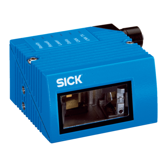
Page 22: Fig. 4-2: Device View Of The Clv62X Bar Code Scanner (Shown Here: Ethernet-Version)
4-pole M12 jack (Ethernet connection) Reading window on front Reading window on side Fig. 4-2: Device view of the CLV62x Bar Code Scanner (shown here: Ethernet-Version) © SICK AG · Division Auto Ident · Germany · All rights reserved 8011965/S345/2008-04-16... -
Page 23: Included In Delivery
“Acrobat Reader“: Freely available PC software for reading PDF files Important The current versions of publications and programs on the CD-ROM can also be downloaded at www.sick.com. 8011965/S345/2008-04-16 © SICK AG · Division Auto Ident · Germany · All rights reserved... -
Page 24: Device Versions
– RS-232, RS-422/485, CAN, two digital switching inputs, two digital switching out- puts, power supply • Ethernet version (revolving connector unit) – Connector 1: Ethernet – Connector 2: RS-232, RS-422/485, CAN, one digital switching input, power supply © SICK AG · Division Auto Ident · Germany · All rights reserved 8011965/S345/2008-04-16... -
Page 25: System Requirements
Host interface: two data output formats configurable, switchable to different physical interfaces, parallel operation possible • Aux interface: fixed data output format, switchable to different physical interfaces, par- allel operation possible 8011965/S345/2008-04-16 © SICK AG · Division Auto Ident · Germany · All rights reserved... -
Page 26: Bar Code Scanner Methods Of Operation
(increment). The reading results are output to the bar code scanner's data interfaces and forwarded to a host/PC. © SICK AG · Division Auto Ident · Germany · All rights reserved 8011965/S345/2008-04-16... -
Page 27: Fig. 4-3: Bar Code Scanner's Methods Of Operation In A Conveyor System (Schematic)
The SOPAS-ET configuration software can, among other things, be used to configure the reading angle and the symbol contrast: , CLV62 , register tab C ROJECT ARAMETER EADING ONFIGURATION ODELABEL ROPERTIES 8011965/S345/2008-04-16 © SICK AG · Division Auto Ident · Germany · All rights reserved... - Page 28 ROJECT ARAMETER ODE CONFIGURATION YMBOLOGIES The selected code types can be configured individually. For this purpose, separate register tabs are available in the configuration software SOPAS-ET. © SICK AG · Division Auto Ident · Germany · All rights reserved 8011965/S345/2008-04-16...
-
Page 29: Fig. 4-4: Reading Operation Mode For The Clv62X Bar Code Scanner In Stand-Alone Operation
(signalisation of readiness). Note The output formats can be configured using the SOPAS-ET configuration software: , CLV62 ROJECT ARAMETER ROCESSING UTPUT ORMAT 8011965/S345/2008-04-16 © SICK AG · Division Auto Ident · Germany · All rights reserved... -
Page 30: Tab. 4-4: Data Interface Function
For the Ethernet version of the bar code scanner, this input is only available with the con- nection module CDB620/CDM420 in combination with the parameter memory module CMC600. © SICK AG · Division Auto Ident · Germany · All rights reserved 8011965/S345/2008-04-16... -
Page 31: Indicators And Control Elements
In case of an error, startup and diagnosis can only be carried out via the SOPAS-ET configu- ration software. The bar code scanner operates fully automated in normal operation. Fur- ther operating elements are not available at the bar code scanner. 8011965/S345/2008-04-16 © SICK AG · Division Auto Ident · Germany · All rights reserved... -
Page 32: Tab. 4-5: Led Indications
Lights up when the physical Ethernet connection is o.k. Tab. 4-5: LED indications Important The “Result“ LED is not coupled with one of the “Result 1“ or "Result 2" outputs. © SICK AG · Division Auto Ident · Germany · All rights reserved 8011965/S345/2008-04-16... -
Page 33: Installation
• Installing the reading pulse sensor for reading pulse triggering Important Do not open the bar code scanner's housing. If the device is opened, the SICK AG warranty shall not apply. Installation preparations The following general requirements should be observed for installation: •... -
Page 34: Fig. 5-1: Example: Fixing The Bar Code Scanner With The Angle With Adapter Plate No. 2042902
– The screw length depends on the thickness of the mounting device. – The maximum thread reach in the bar code scanner is 5 mm (0.2 in) from the hous- ing surface. © SICK AG · Division Auto Ident · Germany · All rights reserved 8011965/S345/2008-04-16... -
Page 35: Installation Location
(see chapter 6.2 Electrical installation preparation, page 43 chapter 5.5.1 Installing connection module CDB620 or CDM420, page 40). 8011965/S345/2008-04-16 © SICK AG · Division Auto Ident · Germany · All rights reserved... -
Page 36: Fig. 5-3: Allocation Of The Scanning Line(S) For The Bar Code And Conveyor System
(chapter 10.2 Specification diagrams, page 73) the height of the reading area is shown in relation to the reading distance a for various resolutions (mod- ule widths). © SICK AG · Division Auto Ident · Germany · All rights reserved 8011965/S345/2008-04-16... -
Page 37: Tab. 5-1: Permitted Reading Angles Between The Scanning Line And Bar Code
Fig. 5-6: Avoiding surface reflection using the line scanner as an example: Angle between emitting light and bar code (tilted away from the plumb line) 8011965/S345/2008-04-16 © SICK AG · Division Auto Ident · Germany · All rights reserved... -
Page 38: Fig. 5-7: Counting Direction Of The Bar Code Along The Scanning Line
Deflection angle α (aperture angle) in scanning direction: 1° = 2 RA (50° = 100 RA) Fig. 5-7: Counting direction of the bar code along the scanning line © SICK AG · Division Auto Ident · Germany · All rights reserved 8011965/S345/2008-04-16... -
Page 39: Installation Of The Bar Code Scanner
5. Screw M5 bolts through the holder and into the bar code scanner's blind hole taps and gently tighten them. 6. Adjusting the bar code scanner, see chapter 7.6.1 Adjusting the bar code scanner, page 8011965/S345/2008-04-16 © SICK AG · Division Auto Ident · Germany · All rights reserved... -
Page 40: Installing External Components
2. Ensure that the incremental encoder has direct and fixed contact with the drive system and that the friction wheel rotates without slipping. © SICK AG · Division Auto Ident · Germany · All rights reserved 8011965/S345/2008-04-16... -
Page 41: Removing The Bar Code Scanner
Chapter 5 CLV62x Bar Code Scanner Removing the bar code scanner Removal of the components is described in chapter 8.5.1 Removing the bar code scanner, page 8011965/S345/2008-04-16 © SICK AG · Division Auto Ident · Germany · All rights reserved... - Page 42 Installation Chapter 5 Operating Instructions CLV62x Bar Code Scanner © SICK AG · Division Auto Ident · Germany · All rights reserved 8011965/S345/2008-04-16...
-
Page 43: Electrical Installation
The following tools and resources are required for electrical installation: • Tool • Digital measuring device (current/voltage measurement) 8011965/S345/2008-04-16 © SICK AG · Division Auto Ident · Germany · All rights reserved... -
Page 44: Electrical Connections And Cables
Standard version: Electrical connections at the bar code scanner with connection cable Fig. 6-2: Ethernet version: Electrical connections at the bar code scanner with connector unit © SICK AG · Division Auto Ident · Germany · All rights reserved 8011965/S345/2008-04-16... -
Page 45: Tab. 6-1: Electrical Connections To The Bar Code Scanner With A Fixed Cable And Connector (Standard Version)
Electrical connections to the bar code scanner with connector unit (Ethernet version) Important Additional digital inputs and outputs are available at connection module CDB620/CDM420 (available from week 07/2008) in combination with the parameter memory module CMC600. 8011965/S345/2008-04-16 © SICK AG · Division Auto Ident · Germany · All rights reserved... -
Page 46: Tab. 6-3: Standard Version: Pin Assignment Of The 15-Pole D-Sub-Hd Cable Connector
Bar code scanner's connections with connector unit (Ethernet version) Signal Function Transmitter+ Receiver+ Transmitter- Receiver- Shield Tab. 6-4: Ethernet version: Pin assignment of the 4-pole M12 socket © SICK AG · Division Auto Ident · Germany · All rights reserved 8011965/S345/2008-04-16... -
Page 47: Tab. 6-5: Ethernet Version: Pin Assignment On The 12-Pole M12 Plug
(standard version) and for the Ethernet version via the CDB620/CDM420 connection module in combination with the parameter memory module CMC600. 8011965/S345/2008-04-16 © SICK AG · Division Auto Ident · Germany · All rights reserved... -
Page 48: Performing Electrical Installation
The output circuit must be electrically separated from the input circuit. This is usually crea- ted by means of a safety transformer in accordance with IEC 742 (VDE 0551). © SICK AG · Division Auto Ident · Germany · All rights reserved 8011965/S345/2008-04-16... -
Page 49: (Ethernet Version)
Pin assignment for the serial auxiliary data interface on the 15-pole D-Sub-HD plug: • RxD = Pin 2 • TxD = Pin 3 • GND = Pin 5 8011965/S345/2008-04-16 © SICK AG · Division Auto Ident · Germany · All rights reserved... -
Page 50: Fig. 6-5: Function Of The Ethernet Interface
Fig. 6-5: Function of the Ethernet interface Important The Ethernet interface has an auto-MDIX function. This automatically sets the speed and any cross connection that is required. © SICK AG · Division Auto Ident · Germany · All rights reserved 8011965/S345/2008-04-16... -
Page 51: Fig. 6-6: Wiring The "Sensor 1" Switching Input On The 15-Pole D-Sub-Hd Plug
If the bar code scanner's reading process should be triggered by an external sensor, the reading pulse sensor is connected to the "Sensor 1" switching input. Fig. 6-6: Wiring the “Sensor 1“ switching input on the 15-pole D-Sub-HD plug 8011965/S345/2008-04-16 © SICK AG · Division Auto Ident · Germany · All rights reserved... -
Page 52: Tab. 6-7: Ratings For The Switching Inputs
To wire the switching inputs using connection module CDB620 or CDM420, see operating instructions "Connection Module CDB620" (no. 8012119, German/English) or "Connection Module CDM420-0001" (no. 8010004, German/English). © SICK AG · Division Auto Ident · Germany · All rights reserved 8011965/S345/2008-04-16... -
Page 53: Tab. 6-8: Ratings For The Switching Outputs
To wire the switching outputs using connection module CDB620 or CDM420, see the oper- ating instructions "Connection Module CDB620" (no. 8012119, German/English) or "Con- nection Module CDM420-0001" (no. 8010004, German/English). 8011965/S345/2008-04-16 © SICK AG · Division Auto Ident · Germany · All rights reserved... -
Page 54: Pin Assignment And Wire Colour Assignment Of The Assembled Cables
SensGND Common ground for the switching inputs – Shield Tab. 6-10: Pin assignment of the 12-pole M12 socket and the 15-pole D-Sub-HD plug © SICK AG · Division Auto Ident · Germany · All rights reserved 8011965/S345/2008-04-16... -
Page 55: Tab. 6-11: Pin Assignment Of The 12-Pole M12 Socket And Wire Colours At The Open End
CAN bus (IN/OUT) white CAN L CAN bus (IN/OUT) blue Tab. 6-12: Pin assignment of the 5-pole M12 plug and wire colours at the open end 8011965/S345/2008-04-16 © SICK AG · Division Auto Ident · Germany · All rights reserved... -
Page 56: Tab. 6-13: Pin Assignment Of The 15-Pole D-Sub-Hd Socket And Wire Colours At The Open Cable End
SensGND Common ground for the switching white-black inputs Tab. 6-13: Pin assignment of the 15-pole D-Sub-HD socket and wire colours at the open cable end © SICK AG · Division Auto Ident · Germany · All rights reserved 8011965/S345/2008-04-16... -
Page 57: Startup And Configuration
: For online help system for the SOPAS-ET con- figuration software Connection cables: See chapter 11.4.7 Accessories: Cables for Ethernet version, page 90 chapter 11.4.8 Accessories: General cables and connectors, page 8011965/S345/2008-04-16 © SICK AG · Division Auto Ident · Germany · All rights reserved... -
Page 58: Establish Communication With The Bar Code Scanner
ETHERNET connection of the bar code scanner (see chapter 11.4.7 Accessories: Cables for Ethernet ver- sion, page 90). Tab. 7-2: Connection between the PC with SOPAS-ET configuration software and the bar code scanner © SICK AG · Division Auto Ident · Germany · All rights reserved 8011965/S345/2008-04-16... - Page 59 (S HECK 3. For configuration of the devices see chapter 7.4.2 Configuring the bar code scanner, page 8011965/S345/2008-04-16 © SICK AG · Division Auto Ident · Germany · All rights reserved...
-
Page 60: First Startup
Load the optimised configuration into the bar code scanner and save permanently • Save the project file with the configuration data of the bar code scanner on the PC © SICK AG · Division Auto Ident · Germany · All rights reserved 8011965/S345/2008-04-16... - Page 61 To save the current parameter set as a PDF, in the menu bar under P select the com- ROJECT mand P PDF F RINT AVE AS 8011965/S345/2008-04-16 © SICK AG · Division Auto Ident · Germany · All rights reserved...
-
Page 62: Default Setting
If the bar code scanner is connected to a connection module CDB620/CDM420 with parameter memeory module CMC600, the parameter set is also saved permanently in the CMC600. Important Once the default setting has been restored, password-protection is deactivated. © SICK AG · Division Auto Ident · Germany · All rights reserved 8011965/S345/2008-04-16... -
Page 63: Adjusting The Bar Code Scanner
4. Align the bar code scanner in such a way that the good read rate is between 70 and 100%. 5. Tighten the screws on the bar code scanner. The bar code scanner is aligned with the bar code. 8011965/S345/2008-04-16 © SICK AG · Division Auto Ident · Germany · All rights reserved... - Page 64 Startup and configuration Chapter 7 Operating Instructions CLV62x Bar Code Scanner © SICK AG · Division Auto Ident · Germany · All rights reserved 8011965/S345/2008-04-16...
-
Page 65: Maintenance
The bar code scanner functions maintenance free. Maintenance is not required to ensure compliance with the bar code scanner's laser class 2. Important Do not open the bar code scanner's housing. If the device is opened, the SICK AG warranty shall not apply. Cleaning the bar code scanner... - Page 66 Important Electrostatic charges cause dust particles to stick to the reading window. This effect can be combated by using anti-static SICK synthetic cleaner (no. 5600006) in combination with a SICK lens cloth (no. 4003353). © SICK AG · Division Auto Ident · Germany · All rights reserved...
-
Page 67: Cleaning Further Optical Effective Surfaces
In order to prevent incorrect switching behaviour, remove soiling from the optical effec- tive surfaces of the external sensors. Fig. 8-2: Cleaning of the external optical sensors (reading pulse generator) 8011965/S345/2008-04-16 © SICK AG · Division Auto Ident · Germany · All rights reserved... -
Page 68: Checking The Incremental Encoder
Connect to the bar code scanner via the SOPAS-ET configuration software, transfer the configuration stored on the PC via download to the bar code scanner and permanently store the configuration there. © SICK AG · Division Auto Ident · Germany · All rights reserved 8011965/S345/2008-04-16... -
Page 69: Troubleshooting
In this case, the bar code scanner returns an error code. • Error codes are written into a status protocol for errors which occur during a reading (chapter 9.3 Status protocol, page 70). 8011965/S345/2008-04-16 © SICK AG · Division Auto Ident · Germany · All rights reserved... -
Page 70: Status Protocol
Only return devices after consultation with the SICK Service. Important Repairs to the bar code scanner should only be performed by qualified and authorised SICK AG service staff. © SICK AG · Division Auto Ident · Germany · All rights reserved... -
Page 71: Technical Data
Ethernet version: no output, 2 outputs via CMC600 in CDB620 PNP, I = max. 100 mA, short circuit-proof, configurable impulse duration (static, 10 ... 1.000 ms) 8011965/S345/2008-04-16 © SICK AG · Division Auto Ident · Germany · All rights reserved... -
Page 72: Tab. 10-1: Technical Specifications For The Clv62X Bar Code Scanner
1) Reading gate: code evaluation time window created internally by the reading pulse 2) Ethernet version: only switching input "Sensor 1" Tab. 10-1: Technical specifications for the CLV62x Bar Code Scanner (line/raster scanner) © SICK AG · Division Auto Ident · Germany · All rights reserved 8011965/S345/2008-04-16... -
Page 73: Specification Diagrams
Tab. 10-2: Reading conditions for all specification diagrams 10.2.1 Reading ranges of the CLV620 Bar Code Scanner (Mid-range) Fig. 10-1: Reading ranges of the CLV620 Bar Code Scanner (with front reading window) 8011965/S345/2008-04-16 © SICK AG · Division Auto Ident · Germany · All rights reserved... -
Page 74: Fig. 10-2: Reading Ranges Of The Clv620 Bar Code Scanner (With Side Reading Window)
(front reading window) Important With the CLV620 Bar Code Scanner with side reading window, the reading distance values in the above diagram have an offset of 16 mm towards the reading window for all scan fre- quencies. -
Page 75: Fig. 10-4: Reading Ranges Of The Clv621 Bar Code Scanner (With Front Reading Window)
Reading ranges of the CLV621 Bar Code Scanner (with front reading window) Fig. 10-5: Reading ranges of the CLV621 Bar Code Scanner (with side reading window) 8011965/S345/2008-04-16 © SICK AG · Division Auto Ident · Germany · All rights reserved... -
Page 76: Fig. 10-6: Clv621: Set Of Characteristic Curves For Scan Frequency, Depending On The Reading Distance And Resolution (Front Reading Window)
With the CLV621 Bar Code Scanner with side reading window, the reading distance values in the above diagram have an offset of 16 mm towards the reading window for all scan fre- quencies. © SICK AG · Division Auto Ident · Germany · All rights reserved 8011965/S345/2008-04-16... -
Page 77: Fig. 10-7: Reading Range Of The Clv622 Bar Code Scanner (With Front Reading Window)
Reading range of the CLV622 Bar Code Scanner (with front reading window) Fig. 10-8: Reading range of the CLV622 Bar Code Scanner (with side reading window) 8011965/S345/2008-04-16 © SICK AG · Division Auto Ident · Germany · All rights reserved... -
Page 78: Fig. 10-9: Clv622: Set Of Characteristic Curves For Scan Frequency, Depending On The Reading Distance And Resolution (Front Reading Window)
With the CLV622 Bar Code Scanner with side reading window, the reading distance values in the above diagram have an offset of 16 mm towards the reading window for all scan fre- quencies. © SICK AG · Division Auto Ident · Germany · All rights reserved 8011965/S345/2008-04-16... -
Page 79: Clv62X Bar Code Scanner Dimensional Drawings
10.3.1 CLV62x-0000 and CLV62x-1000 Bar Code Scanner dimensional drawing Fig. 10-10: Standard version: Dimensions of the bar code scanner with front reading window (CLV62x-0000 and CLV62x-1000) 8011965/S345/2008-04-16 © SICK AG · Division Auto Ident · Germany · All rights reserved... -
Page 80: Fig. 10-11: Standard Version: Dimensions Of The Bar Code Scanner With Side Reading Window (Clv62X-2000 And Clv62X-3000)
10.3.2 CLV62x-2000 and CLV62x-3000 Bar Code Scanner dimensional drawing Fig. 10-11: Standard version: Dimensions of the bar code scanner with side reading window (CLV62x-2000 and CLV62x-3000) © SICK AG · Division Auto Ident · Germany · All rights reserved 8011965/S345/2008-04-16... -
Page 81: Fig. 10-12: Ethernet Version: Dimensions Of The Bar Code Scanner With Front Reading Window (Clv62X-0120 And Clv62X-1120)
10.3.3 CLV62x-0120 and CLV62x-1120 Bar Code Scanner dimensional drawing Fig. 10-12: Ethernet version: Dimensions of the bar code scanner with front reading window (CLV62x-0120 and CLV62x-1120) 8011965/S345/2008-04-16 © SICK AG · Division Auto Ident · Germany · All rights reserved... -
Page 82: Fig. 10-13: Ethernet Version: Dimensions Of The Bar Code Scanner With Side Reading Window (Clv62X-2120 And Clv62X-3120)
10.3.4 CLV62x-2120 and CLV62x-3120 Bar Code Scanner dimensional drawing Fig. 10-13: Ethernet version: Dimensions of the bar code scanner with side reading window (CLV62x-2120 and CLV62x-3120) © SICK AG · Division Auto Ident · Germany · All rights reserved 8011965/S345/2008-04-16... -
Page 83: Appendix
DDRESSING MODE Y NAME ing C ONNECT The connection with the bar code scanner is established. The command strings can be transferred. 8011965/S345/2008-04-16 © SICK AG · Division Auto Ident · Germany · All rights reserved... -
Page 84: Calculating The Code Length Of A Bar Code
Extended for code 39. The number of characters in the bar code scanner's data string may be greater than the number of characters in the print image for code 93, code 128 and EAN 128, since they are made up of several character sets. Tab. 11-1: Help table for calculating the code length of a bar code © SICK AG · Division Auto Ident · Germany · All rights reserved 8011965/S345/2008-04-16... -
Page 85: Ordering Information For Bar Code Scanner And Accessories
Raster scanner On side Cable with connector 1041799 CLV622-3120 Raster scanner On side Connector unit on device Tab. 11-2: Variants of the CLV62x Bar Code Scanner 8011965/S345/2008-04-16 © SICK AG · Division Auto Ident · Germany · All rights reserved... -
Page 86: Tab. 11-3: In Stock Accessories: Installation Accessories
Angle with adapter plate incl. installation material. For dimensional drawing, see chapter 11.5.4 Dimensional drawing of bracket with adapter plate no. 2042902, page 95 Tab. 11-3: In stock accessories: Installation accessories © SICK AG · Division Auto Ident · Germany · All rights reserved 8011965/S345/2008-04-16... -
Page 87: Tab. 11-4: In Stock Accessories: Connection Modules
1) When using a SICK scanner standard connection cable 2) Dormant (no installation or electrical installation), up to –20 °C (-4 °F) Tab. 11-4: In stock accessories: Connection modules 8011965/S345/2008-04-16 © SICK AG · Division Auto Ident · Germany · All rights reserved... - Page 88 Operating voltage 18 ... 30 VDC using CDM420, current consump- tion 2 W • Operating temperature 0 ... +40 °C • Configuration with PC software "ComPro" (included in delivery) • Configuration with SOPAS-ET from Q4/2007 © SICK AG · Division Auto Ident · Germany · All rights reserved 8011965/S345/2008-04-16...
-
Page 89: Tab. 11-5: In Stock Accessories: Extensions For Connection Modules
(without direct connections) • Weight approx. 590 g (9.17oz) • Configuration: via 3 x rotary switches and SOPAS-ET Tab. 11-6: In stock accessories: Separate field bus modules 8011965/S345/2008-04-16 © SICK AG · Division Auto Ident · Germany · All rights reserved... -
Page 90: D-Sub-Hd Plug
6.2 mm (0.24 in), shielded, with 12-pole M12 round 0.14 mm² socket and open end. (26 AWG) Tab. 11-8: In stock accessories: Cables and connectors for the Ethernet version of the bar code scanner © SICK AG · Division Auto Ident · Germany · All rights reserved 8011965/S345/2008-04-16... - Page 91 PROFIBUS connection, shielded 2 x 0,34 mm² Sold by the PROFIBUS network (28 AWG) metre 4038847 Sealing rubber IP 65 for extension cables with 15- pole D-Sub connectors 8011965/S345/2008-04-16 © SICK AG · Division Auto Ident · Germany · All rights reserved...
-
Page 92: Tab. 11-9: In Stock Accessories: General Cables And Connectors For Bar Code Scanner
The SICK catalog "SENSICK Sensoren for Automation" (order no. 8006530, English) con- tains a large selection of photoelectric reflex switches and photoelectric proximity switches as well as accessories (holders, connection cables). © SICK AG · Division Auto Ident · Germany · All rights reserved 8011965/S345/2008-04-16... -
Page 93: Dimensional Drawing Accessories
Included to fix the bar code scanner to the bracket: 2 x cylinder head screws M5 x 8 mm (0.32 in), with hexagon socket, self-locking Fig. 11-1: Dimensions of the fixing bracket no. 2020410 8011965/S345/2008-04-16 © SICK AG · Division Auto Ident · Germany · All rights reserved... -
Page 94: Fig. 11-2: Dimensions Of The Quick Release Clamp No. 2025526
Included to fix the bar code scanner to the clamp: 2 x cylinder head screws M5 x 8 mm (0.32 in), with hexagon socket, self-locking Fig. 11-2: Dimensions of the quick release clamp no. 2025526 © SICK AG · Division Auto Ident · Germany · All rights reserved 8011965/S345/2008-04-16... -
Page 95: Fig. 11-3: Dimensions Of The Round Rod Holder No. 2042802
11.5.4 Dimensional drawing of bracket with adapter plate no. 2042902 Fig. 11-4: Dimensions of the bracket with adapter plate no. 2042902 (here shown only the bracket) 8011965/S345/2008-04-16 © SICK AG · Division Auto Ident · Germany · All rights reserved... -
Page 96: Supplementary Documentation
Description of setting up a CAN scanner net- work (electrical connection, configuring the bar code scanner, functions) and integrating it in a CAN open network Tab. 11-10: Supplementary documentation © SICK AG · Division Auto Ident · Germany · All rights reserved 8011965/S345/2008-04-16... -
Page 97: Glossary
(e.g. multiplexer, master/slave). Access to the CLV62x Bar Code Scanner for configuration is possible via the CAN interface (network) using the SOPAS-ET configuration software in remote mode. Code geometry Code length and height dimensions. 8011965/S345/2008-04-16 © SICK AG · Division Auto Ident · Germany · All rights reserved... - Page 98 However, the application-specific basic setting enables all parameter values except for those for the communication parameter to be set to the factory default settings. The existing communication with the bar code scanner remains unaffected. © SICK AG · Division Auto Ident · Germany · All rights reserved 8011965/S345/2008-04-16...
- Page 99 Digital switching inputs and outputs of the bar code scanner. Good read The defined evaluation condition(s) were successfully met during the last reading pulse in the reading process. 8011965/S345/2008-04-16 © SICK AG · Division Auto Ident · Germany · All rights reserved...
- Page 100 Allows, among other functions, the output of the reading result in tel- egram form to the host/PLC. Physically switchable to RS-232/RS-422/485 and Ethernet (port 2112) or CAN. Works as a gateway in conjunction with the SICK-specific CAN-SENSOR network. Provides various transfer protocols (except for CAN).
- Page 101 The "Result" LED is not coupled with one of the result outputs. It only shows status "Good read" for approx. 100 ms when generating reading results via the data interface. 8011965/S345/2008-04-16 © SICK AG · Division Auto Ident · Germany · All rights reserved...
- Page 102 (configuration, displaying reading events, diagnosis) as well as for preparatory offline configuration of stand-alone devices or the grouping of the same/different SOPAS-ET-compatible SICK devices in a project. The pa- rameters are exchanged device-specific with the bar code scanner/the devices via upload and download.
- Page 103 User interface Windows-oriented input interfaces in the SOPAS-ET configuration software for operation and configuration of the bar code scanner. 8011965/S345/2008-04-16 © SICK AG · Division Auto Ident · Germany · All rights reserved...
-
Page 104: Ec Declaration Of Conformity
The complete EC Declaration of Conformity and the list of device versions and the standards met can be requested from SICK AG. Fig. 11-5: EC Declaration of Conformity for the bar code scanner (page 1, scaled down version) © SICK AG · Division Auto Ident · Germany · All rights reserved 8011965/S345/2008-04-16... -
Page 105: Code Samples Of Bar Codes (Selection)
Module width 0.35 mm Module width 0.50 mm (11.8 mil) (13.8 mil) (19.7 mil) Fig. 11-6: Code samples of bar codes of various module widths (print ratio 2:1) 8011965/S345/2008-04-16 © SICK AG · Division Auto Ident · Germany · All rights reserved... - Page 106 Deutschland Singapore España Suomi France Sverige Great Britain Taiwan India Türkiye Italia USA/Canada/México Japan Nederlands Norge Österreich www.sick.com SICK AG | Waldkirch | Germany | www.sick.com © SICK AG · Division Auto Ident · Germany · All rights reserved 8011965/S345/2008-04-16...
Need help?
Do you have a question about the CLV620 and is the answer not in the manual?
Questions and answers