
Subscribe to Our Youtube Channel
Related Manuals for Trotec ProMarker OEM


Summary of Contents for Trotec ProMarker OEM
- Page 1 ProMarker OEM ProMarker OEM Operating manual Operating manual 8021 8021 OM 8021_5.0_EN (08/2019) OM 8021_5.0_EN (08/2019) ENGLISH (Translation) ENGLISH (Translation)
- Page 2 Trotec Laser GmbH Trotec Laser Pty Ltd Trotec Laser België Trotec Laser Belgique +43 7242 239-7070 +61 26413-5904 +31 850 70 51 55 service-at@troteclaser.com service@troteclaser.com.au support@troteclaser.nl Trotec Laser Canada Trotec Laser AG Trotec Laser GmbH +1 800 663 1149-902 +41 32387-1611 +86 189 500 735 62 techsupport@troteclaser.ca...
- Page 3 Trotec Laser GmbH Freilingerstraße 99 4614 Marchtrenk, Austria Invoice Address: Linzerstraße 156 4600 Wels, Austria Tel.: +43 7242 239-0 General contact to Technical Support: Tel.: +43 7242 239-7000 E-mail: techsupport@troteclaser.com www.troteclaser.com ENGLISH (Translation)
- Page 4 Technical Changes Technical specifications are subject to change without notice. Trotec Laser GmbH reserves the right to improve or modify any of the products without prior notice. © Copyright This documentation with all illustrations is intellectual property of Trotec Laser GmbH.
-
Page 5: Table Of Contents
Content Content Introduction......................... 8 General Information....................9 Information about this manual....................9 2.1.1 Storage of the manual......................9 2.1.2 General instructions for using the manual................9 Explanation of symbols......................11 Liability and warranty......................12 Scope of delivery (standard configuration)................12 Type plate..........................14 Safety......................... - Page 6 Content Transport and Storage.....................32 Transport conditions......................32 Storage conditions........................ 32 Place of storage........................33 Transport inspection and reporting of defects..............33 Setup and installation....................34 For your safety........................34 Temperature and humidity....................34 Installation location.......................34 Mechanical installation......................35 7.4.1 Installation of the marking head................... 35 Electrical installation......................
- Page 7 Content Contact details......................56 Disassembly......................57 Disposal........................58 Appendix........................59 15.1 Datasheet 8021 ProMarker OEM..................60 15.2 CE 8021 ProMarker FL......................65 ENGLISH (Translation)
-
Page 8: Introduction
Introduction Introduction The ProMarker is a second generation of a high quality marking laser. The Yb fiber laser source means the system has an extremely long life cycle and minimal maintenance costs. This system is maintenance free apart from the filter pad and processing lens. The combination of a high quality galvanometer scanner and a fiber laser produce highly precise marking results in short marking times. -
Page 9: General Information
General Information General Information For reasons of better legibility, gender-neutral form of address (e. g. "he/she") are not used in the operating manual. It is expressly stated that in all text passages where natural persons or groups of persons are mentioned, people of both sexes are always meant. - Page 10 General Information The ProMarker OEM is a class 4 laser marking system according to IEC 60825-1 "safety of laser products". If the ProMarker OEM is integrated into a system as an OEM component, the operator bears sole responsibility for compliance with the legal standards and safety guidelines.
-
Page 11: Explanation Of Symbols
General Information Explanation of symbols Important technical safety notes and instructions in this manual are indicated by symbols. It is important to observe and follow these notes and instructions on workplace safety. Avoid accidents, personal injury and material damage to property by acting with extreme caution. Danger This symbol indicates an imminently hazardous situation which, if not avoided, will result in death or serious injury. -
Page 12: Liability And Warranty
Nonobservance of the operation, maintenance and service instructions described within this manual absolves Trotec Laser GmbH from any liability in case of a defect. Furthermore, Trotec Laser GmbH shall accept no liability whatsoever for damage caused by the use of non- original parts and accessories. - Page 13 General Information Cable set (1 long cable (W203) + 1 short cable (W503)) Cable COM connection (W505) Green bridging plugs (X11, X61, X71) Black bridging plug (X31) Galvanometer scanner controller card (for PC) Slot Combiner print (X103, X53) Slot cover plate 9pin (COM FL) 2 keys for the laser rack CD with marking software Lens cleaning kit...
-
Page 14: Type Plate
General Information Type plate The type plate contains information regarding the serial number, manufacturer, date of manufacture, connection values and consumption data. The type plate is located on the reverse side of the laser rack. Enter the serial number, model and year of construction of the machine here. This data is important should the unit experience a fault and for ordering replacement parts. -
Page 15: Safety
Safety Safety TO AVOID POSSIBLE HARM READ AND FOLLOW THESE INSTRUCTIONS. The machine is built at the time of it's development and production according to applicable, established technical rules and is considered to be safe to operate. Dangers can be caused by the machine if the machine: is operated by unqualified personnel, the personnel have not been trained, the machine is used improperly or not as intended,... - Page 16 Safety Warning Risk posed by incorrect operation by unauthorized individuals. Setting and operating the machine with limited knowledge of its function can lead to injury and/ or damage to the machine. – Never leave the machine unattended while in operation. –...
-
Page 17: Intended Use
The machine may only be operated by suitably trained individuals. – Observe effective safety regulations and the procedures described in this operating manual. If the intention is to use the system for other applications, Trotec Laser GmbH should be informed in advance. 3.1.2... -
Page 18: Machine Modification
The service operation is therefore declared as laser class 4 (US: class IV) and proper precautions need to be taken (see "Laser classification"). 3.1.6 Applicable safety regulations The following directives and guidelines must be observed to avoid hazards when operating Trotec laser systems: Guidelines/Regulations 2006/42/EC... - Page 19 Therefore, always observe the directives as well as the regulations of the institutions for statutory accident insurance association applicable to you. The operator is responsible for fulfilling all safety requirements, as Trotec Laser GmbH has no influence on the proper use of the machine.
-
Page 20: Laser Safety
Safety Laser safety 3.2.1 Laser classification The laser safety class indicates the risk potential based on the level of accessible laser radiation. The ProMarker is a laser class 4 product and complies to the latest safety norms and regulations (IEC 60825-1). - Page 21 Safety Class 1 The accessible laser radiation of Class 1 laser systems does not pose any hazard for the skin or eyes. In order to operate the Promarker as a Class 1 laser system, the following points must be observed: Notice –...
-
Page 22: Areas Of Responsibility
Safety Areas of responsibility 3.3.1 Responsibilities of the operating company The operator has the following responsibilities: It is the responsibility of the operator to comply with the national official and statutory regulations for the • operation of a class 4 (US: class IV) laser system or laser system with a build in laser source of class 4 (US: class IV). -
Page 23: Responsibilities Of The Operating Personnel
Always keep clean the machine and its components such as lens and mirrors. • Caution The adjustment of the beam path may only be carried out by service personnel of Trotec Laser GmbH. Requirements for operating an service personnel The requirements for the operating and service personnel are: The personnel must have read and understood this manual and in particular the "Safety"... -
Page 24: Machine Identification (Warning And Safety Stickers)
Safety Machine identification (warning and safety stickers) Notice The warning signs on the device indicate potential hazards and provide information regarding the laser device performance data. ENGLISH (Translation) -
Page 25: Secondary (Indirect) Hazards
Safety Secondary (indirect) hazards 3.6.1 Fire hazard Warning Fire hazard Fire hazard from gas and processing of inflammable materials. – Do not operate the device without supervision. – Keep CO fire extinguisher ready at hand in the immediate vicinity of the device. If a main laser beam comes into contact with inflammable material, e.g. -
Page 26: In Case Of Emergency
• endangering yourself. Notice After a deletion, Trotec Technical Support must be involved before the system is put back into operation. In case of accident, First Aid If due to laser irradiation eye injury has occurred (upon exceedance of the maximum allowable irradiation •... -
Page 27: Technical Data
Technical Data Technical Data The technical data sheet can be found in the appendix of this manual. General description All electronic components are integrated in the machine. All necessary connectors are located on the reverse side of the laser rack. ENGLISH (Translation) -
Page 28: Laser Rack Dimensions
Technical Data Laser rack dimensions ENGLISH (Translation) -
Page 29: Marking Head Dimensions
Technical Data Marking head dimensions ENGLISH (Translation) -
Page 30: Before Commissioning
Record all details in writing immediately. • Note all claims on the transportation documents. • Photograph any damage. • Send report to Trotec Laser GmbH. • After unloading: Inspect the machine and machine components for transportation damage. • Check the delivery for completeness. - Page 31 Before commissioning Warning On delivery the marking head is firmly attached to the laser rack using the fiber optic cable. The fiber optic cable is enclosed with the jumper cables in a black protective tube for protection. Avoid any unnecessary stretching or bending of the fiber optic cable. This could damage the fiber optic cable.
-
Page 32: Transport And Storage
Transport and Storage Transport and Storage Transport conditions When transporting outside, always transport in a covered vehicle or one with sufficient weather-proofing. • Protect the machine against transportation damage using straps and inserts, and leave sufficient • distance between other transported items. Ambient temperature for transportation: •... -
Page 33: Place Of Storage
Transport and Storage Place of storage Storage room or boxed with sufficient weatherproofing. The storage location must be free from corrosive elements, fumes and flammable materials. Transport inspection and reporting of defects Immediately after receipt inspect the delivery to ensure that it is complete and has not suffered any •... -
Page 34: Setup And Installation
Setup and installation Setup and installation For your safety Notice The setup has to be carried out by Technical Support. Temperature and humidity Ambiente conditions Operating temperature (ambiente temperature): +15 °C to +25 °C (59 °F to 77 °F) Relative humidity: 45% to 65%, non-condensing If the system has been exposed to large temperature fluctuations, it must first be brought back to room •... -
Page 35: Mechanical Installation
Setup and installation Mechanical installation 7.4.1 Installation of the marking head The correct, stable and reproducible alignment of the working head in relation to the workpiece to be marked is a prerequisite for faultless marking results. The marking head should therefore be installed with appropriate care. - Page 36 Setup and installation Alignment The focal plane lies parallel to the working head base plate. When installing the marking head it is therefore important to ensure that the marking head base plate is aligned as parallel as possible to the intended processing plane.
-
Page 37: Electrical Installation
Setup and installation Laser rack and PC The laser rack and the PC should be located next to or directly above one another if possible in order for the modules to be connected to one another with the cables provided. When installing in a control cabinet or rack, ensure there is sufficient ventilation. -
Page 38: Overview Marking Head Interface (Back Side)
Setup and installation 7.5.1 Overview marking head interface (back side) Notice The cables are already connected to the marking head on delivery. Caution The fiber cable should only be disconnected from the marking head by trained service personnel. Before working on the system, remove the power plug! ENGLISH (Translation) -
Page 39: Overview Pc Interface (Back Side)
Setup and installation 7.5.2 Overview PC interface (back side) Connectors X93 and X103 are joined directly via a short cable. Connector X53 is joined to X51 on the laser rack by using another cable. Connector X83 is joined through the black tube to X82 on the marking head. 7.5.3 Mains connection Laser rack and PC have a cold device socket on the rear for the cold device cables supplied. -
Page 40: Overview Laser Rack Interface (Back Side)
Setup and installation 7.5.4 Overview laser rack interface (back side) Notice Before the laser marker can be put into operation, the external safety circuits and the external start and stop signals must be connected. Caution When making these connections, the operator must ensure that all safety circuits comply with the respective valid national standards and guidelines for the use of laser devices. - Page 41 Setup and installation X61 – Exhaust system This connector is used to control, start and stop a Trotec extraction unit. Only use the original cable supplied. X71 – Start / Stop The X71 connector may be used to send start and stop signals via an external controller or receive a signal from the laser.
-
Page 42: Interface Pin Configuration
Setup and installation 7.5.5 Interface pin configuration X11 – Safety circuit (Emergency stop button / interlock safety switch / external messages) X31 - External panel ENGLISH (Translation) - Page 43 Setup and installation X71 – Start / Stopp ENGLISH (Translation)
-
Page 44: Operation
Operation Operation Installation inspection In order to ensure the unit is installed correctly, the following points should be checked: Ensure the power supply corresponds to the correct connection values and suitable fuses have been • used. Has the mechanical and electrical installation been performed correctly and completely? •... -
Page 45: Control Panel
Operation Control panel Number Description Types ❶ Main switch switch ❷ System ready control lamp ❸ Shutter control lamp ❹ Laser busy control lamp ❺ Emergency stop button switch ❻ Error reset button ❼ Key switch switch ENGLISH (Translation) -
Page 46: Power On/Off
Operation Power On/Off 1. Press the master switch ❶ on the laser rack. 2. The switch is illuminated in green and the two status lamps on the marking head also illuminate in green (shutter closed). 3. Put the key in the key switch ❼ (vertically) and turn 90° to the right. 4. -
Page 47: Emission Indicator
Operation Emission indicator The laser system is fitted with an emission indicator. If the system is switched on or the safety lock is open, there is usually a possibility that laser radiation will be emitted. This is signalled by a separate indicator and/ or an illuminated "Shutter"... -
Page 48: Focusing
Operation Focusing Notice It is absolutely essential to maintain the correct focal distance for every laser marking process. Only when in focus will the laser beam achieve the power density necessary for permanent and clearly legible marking. Prior to any marking it is therefore necessary to set the correct focal distance between the marking head and the workpiece. -
Page 49: Ingetration / Connection
Ingetration / Connection Ingetration / Connection Switching sequences Switching sequence diagrams are provided for various standard processes which indicate the interplay of the individual signals. ENGLISH (Translation) - Page 50 Ingetration / Connection ENGLISH (Translation)
-
Page 51: Maintenance
Maintenance Maintenance 10.1 Safety notes Caution Before any maintenance work takes place, ensure that the power supply has been switched off and the system is de-energised. Notice All maintenance work must be carried out according to the safety regulations. In order to ensure the maximum availability and lifetime of the system, we recommend you regularly check the filter system and ventilation and keep the surrounding area clean. -
Page 52: Cleaning The Optics
Maintenance 10.3 Cleaning the optics This system is fitted with high quality optical components, which under normal operating conditions are maintenance free for their lifetime. However, it may be necessary to clean output lenses, e.g. the scanner flat field lens (f-theta objective) if it becomes covered in dust or fumes. Notice Never touch the optical components with your fingers! Oily or dirty hands may damage the lens surfaces. -
Page 53: Troubleshooting
This chapter should assist maintenance personnel with the identification and resolution of operational faults based on error messages and symptoms. Danger Maintenance and repair work should only be carried out by Trotec Laser GmbH or one of its authorized personnel under observation of the safety regulations. 11.1... -
Page 54: Possible Error Messages
Warning System errors which cannot be reset or which indicate a hardware error should only be resolved by Trotec Laser GmbH trained service personnel. Error message Cause Card off line. - Page 55 Troubleshooting Error message Cause 24V monitoring. Shutter temperature. Required shutter position. ENGLISH (Translation)
-
Page 56: Contact Details
Contact details Contact details Technical Support In case of questions, contact our experienced Technical Support in your local area. For global service contact numbers and further information please see our website, section "Support": www.troteclaser.com When calling, please make sure that the machine is in your immediate vicinity, and that you have the following information ready (see response form): At which working process did the problem occur? What you have done so far to correct the problem. -
Page 57: Disassembly
Disassembly Disassembly Warning Danger of injury when disassembling the machine. There is danger of injury when disassembling the machine. Always wear suitable protective clothing (e.g. safety goggles, safety shoes, safety gloves). Warning Current Electric current. The machine must be disconnected from the main power supply. Notice –... -
Page 58: Disposal
Disposal Disposal Disposal Do not dispose of the machine with domestic waste! Electronic devices have to be disposed of according to the regional directives on electronic and electric waste disposal. In case of further questions, please ask your supplier. Use suitable tools if you have to dissemble the machine. All parts need to be sorted into the individual material types and be disposed of according to the regional directives on electronic and electric waste disposal. -
Page 59: Appendix
Appendix Appendix ✓ Technical Data ✓ Conformity Declaration Acceptance report Response form Training verification form ENGLISH (Translation) -
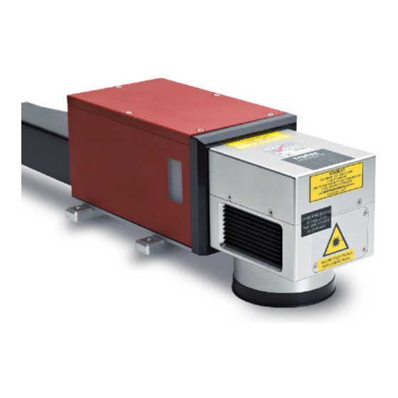
Page 60: Datasheet 8021 Promarker Oem
ProMarker OEM Technical Datasheet High-Speed Laser Marking as Easy as Printing OEM fiber laser head for easy integration Laser Laser Ytterbium pulsed fiber lasers, maintenance free Wavelength 1064 nm ± 8 Pulse duration 100 ns ± 20 Beam quality M² < 2 Power stability better ±... - Page 61 ProMarker OEM Technical Datasheet Control Windows XP (SP2) or Windows 7 (32 bit) Computer requirements CD Drive, 256 MB RAM, > 200 MB space on HD, 1 GHz Processor, 1 free PCI Slot + 2 empty slot covers in casing...
- Page 62 ProMarker OEM Technical Datasheet Dimensions / Installation / Laser Safety Marking head: 120 x 138 x 528 mm³ Dimensions (W x H x D) Laser rack unit: 483 x 140 x 686 mm³ (equals 3RU, 19" compatible) Overall length: 3 m...
- Page 63 ProMarker OEM Technical Datasheet 483 mm Figure 1: Laser rack Laser rack: 482,6 x 140 x 686 mm³ (W x H x D) (equals 3RU, 19" compatible) 528 mm plus. 130mm bending radius for fiber 120 mm Figure 2: Marking head * with F = 160 mm www.troteclaser.com...
- Page 64 ProMarker OEM Technical Datasheet Working distances for ProMarker The working distance is measured between the lower edge of the marking head and the work piece as shown in Figure 3. Because the actual values for two lenses of the same focal length may vary slightly, it is recommended to check the working distance after the lens has been changed.
-
Page 65: Ce 8021 Promarker Fl
TROTEC Laser GmbH Linzer Straße 156, A-4600 Wels Authorized person for the compilation of technical documentation Gerhard KREMPL, TROTEC Laser GmbH, Linzer Straße 156, A-4600 Wels We hereby certify that ProMarker FL Modell N° 8021 ProMarker FL 10/20 in its conception, construction and form put by us into circulation is in accordance with all the relevant essential health and safety requirements of the EC machinery directive 2006/42/EEC.
Need help?
Do you have a question about the ProMarker OEM and is the answer not in the manual?
Questions and answers