Table of Contents
Advertisement
Quick Links
Advertisement
Table of Contents

Related Manuals for Trotec PD200


Summary of Contents for Trotec PD200
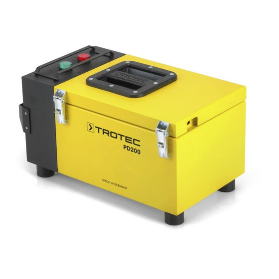
- Page 1 PD200 OPERATING MANUAL PULSE CURRENT MEASURING SYSTEM...
-
Page 2: Table Of Contents
11 .1 Pulse generator PD200 G. . . . . . . . . A - 12 4 .2 Pulse receiver PD200 E . . . . . . . . . . . . A - 05 05. -
Page 3: Intended Use
Any other use is considered misuse and contrary to measured results is strictly excluded . the intended use . 02. Intended use The PD200 system is a professional measuring device based on the pulse current method for the pinpoint location of grounded leaks in non-conducting plastic foils . -
Page 4: Optional Accessories
• 1 x connection cable with clip terminal in the lid, black length 8 m – • 1 x reel PD200 loop wiring, length 200 m • 1 x reel PD200 earth cable extension with banana jack, red, length 25 m –... -
Page 5: Operating Elements, Displays And
• pressure switch, green, for switching on the external earthing • positive connector, red • negative connector, black • transport handle – A - 4 Operating manual – pulse current measuring system PD200... -
Page 6: Pulse Receiver Pd200 E
5.2 Voltage testing pulse generator PD200 G Plug the power cable into an earthed safety socket . to position "I" and the green Flip the rocker switch – indicator light indicates the mains connection . A - 5 Operating manual – pulse current measuring system PD200... -
Page 7: Checking The Functional Interaction
The PD200 pulse generator gives of current pulses with a voltage of 40 V . The current finds its path to the point of leakage via the moisture . The PD200 receiver is used to measure the potential difference . The... -
Page 8: Preparing The Measurement
At any rate, the roof seal to be checked must be suf- ficiently damp to conduct the current pulses . The roof ceiling boarding seal may have to be watered additionally . wall roof trim A - 7 Operating manual – pulse current measuring system PD200... -
Page 9: Using The Gravel Claw
6.4 Preparation cold roof Timber structures are electrically non-conducting . Therefore, the preparations differ . 6.4.1 Installation of loop wiring Please proceed as described in point 6 .3 .1 . A - 8 Operating manual – pulse current measuring system PD200... -
Page 10: Connecting The Pulse Generator A
Please proceed as described in point 6 .3 .3 . red positive connector . Now attach the bare end of the wire to the wet ceiling area underneath the flat roof . A - 9 Operating manual – pulse current measuring system PD200... -
Page 11: Detection
. Having removed the fill, the leak should be visible and can be repaired . A - 10 Operating manual – pulse current measuring system PD200... -
Page 12: Supposed Leak At The Centre
. The measure- ment is effected by applying the same method as on the roof . Here, too, sufficient moisture covering the entire area is required for the measurement . A - 11 Operating manual – pulse current measuring system PD200... -
Page 13: Troubleshooting
9 V (6 x 1 .5 V) Required for the operation of pulse receiver PD200 E are 6 customary batteries of type LR06 / AM-3 | AA | Mignon . Detach the 4 screws, lift off the cover, remove the empty batteries and replace them with new ones . -
Page 14: Particular Equipment Features
• robust, splash-proof design tive 2006/66/EC of the European Parliament and of the Council of 6 September 2006 on batteries and • easy handling of pulse receiver PD200 E due to less accumulators . Please dispose of batteries and accu- operating elements mulators according to the relevant legal requirements . - Page 15 Notes A - 14 Operating manual – pulse current measuring system PD200...
- Page 16 Trotec GmbH & Co. KG Grebbener Str. 7 D-52525 Heinsberg +49 2452 962-0 +49 2452 962-200 info@trotec.com www.trotec.com...
Need help?
Do you have a question about the PD200 and is the answer not in the manual?
Questions and answers