Table of Contents
Advertisement
Quick Links
Advertisement
Table of Contents

Summary of Contents for Trotec PD200
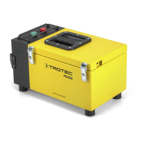
- Page 1 PD200 OPERATING MANUAL PULSE CURRENT MEASURING SYSTEM...
-
Page 2: Table Of Contents
Information marked with this symbol indicates that the presented is excluded from any liability or guarantee. operating manual must be observed. Liability for damages which have been caused by utilising the presented measured results is strictly excluded. pulse current measuring system PD200... - Page 3 To use the device for its intended use, only use accessories and Warning of electrical voltage spare parts which have been approved by Trotec. Risk of death due to electric shock! The device is a professional measuring device based on the...
-
Page 4: Information About The Device
This way you are led to the leak, i.e. to the position where moisture enters. A Pulse generator B Loop wiring C Leak D Potential lines pulse current measuring system PD200... -
Page 5: Transport And Storage
• 1 x Transport case Transport case with carrying handle • 1 x Integrated pulse generator PD200 G Pulse generator PD200 G • 1 x Pulse receiver PD200 E with carrying strap Black connection cable with clip terminal • 1 x Connection cable with clip terminal Loop wiring reel •... -
Page 6: Operation
(to at least 30 µA), the battery capacity is earthing sufficient and the device is ready for use. Positive socket, red For connection with the pulse 2. Turn the 6-position rotary switch (21) to position 4. receiver Negative socket, black pulse current measuring system PD200... - Page 7 ð The needle should now deflect to the left. J Greening K Vegetation layer L Filter layer M Drainage layer F Roof seal G Thermal insulation H Vapour barrier I Supporting structure (solid – µA ceiling) pulse current measuring system PD200...
- Page 8 G Thermal insulation H Vapour barrier R Ceiling boarding S Wall T Roof trim Installation of loop wiring Schematic cross-section warm roof B Loop wiring U Fill Schematic cross-section greened roof B Loop wiring U Fill pulse current measuring system PD200...
- Page 9 6. Carefully insert the claw in the gravel by pulling and move µA backwards one step at a time, so that the loop wiring disappears underneath the gravel fill. 7. On a sample basis check that the loop is placed directly on the roof membrane. pulse current measuring system PD200...
- Page 10 5. The black connection cable (3) is connected to the loop 2. Plug the end of the red connection cable (9) into the red wiring by use of the clip terminal. positive socket (23). The pulse receiver is connected as described. pulse current measuring system PD200...
- Page 11 5. Having removed the fill, the leak should be visible and can be repaired. pulse current measuring system PD200...
- Page 12 On roofs without fill a moisture film is all it takes, as long as it covers the entire area. Cold roofs might necessitate a certain waiting period. B Loop wiring pulse current measuring system PD200...
-
Page 13: Available Accessories
6. Store the device according to the Storage chapter. Available accessories Designation Article number Gravel claw 3.510.010.003 for laying and inserting loop wiring under the gravel fill Loop wiring spare reel, length 200 m 3.510.010.005 Spare earth cable extension, red, length 3.510.010.004 25 m pulse current measuring system PD200... -
Page 14: Errors And Faults
Directive 2006/66/EC of the acoustic signal is emitted European Parliament and of the Council of 6 September 2006 (current of more than 1 A) on batteries and accumulators. Please dispose of batteries and accumulators according to the relevant legal requirements. pulse current measuring system PD200... - Page 15 Trotec GmbH Grebbener Str. 7 D-52525 Heinsberg +49 2452 962-400 +49 2452 962-200 info@trotec.com www.trotec.com...


Need help?
Do you have a question about the PD200 and is the answer not in the manual?
Questions and answers