
Subscribe to Our Youtube Channel
Related Manuals for CTS ESW-3128 Series


Summary of Contents for CTS ESW-3128 Series
- Page 1 ESW-3128 Series 24 PORTS 10/100/1000BASE-T RJ-45 WITH 4 COMBO PORTS (10/100/1000BASE-T, 100/1000BASE-X SFP) UPLINK MANAGEMENT SWITCH User’s Guide Version 0.91...
- Page 2 Trademarks CTS is a registered trademark of Connection Technology Systems Inc All trademarks belong to their respective proprietors Contents are subject to change without prior notice.
- Page 3 Revision History Version Date Description 0.90 20150610 First release 0.91 20150720 Key Feature Rearrangement...
-
Page 4: Table Of Contents
Table of Contents 1. INTRODUCTION ................... 5 1.1 The Managed Switch ................5 1.2 Key Features .................... 6 1.3 Front & Rear Panel ................... 7 1.4 Cable Specifications ................. 7 1.5 Network Management ................8 2. INSTALLATION ................... 10 2.1 Requirement ................... 10 2.2 Checking the Package Contents ............ -
Page 5: Introduction
1. INTRODUCTION The Managed Switch is designed to meet the emerging FTTX & Metro Ethernet requirement. Its low profile appearance with 1U height and standard rack- mount size achieves the highest density within a single rack. When massive fiber ports need to be deployed, the Managed Switch provides the best performance and price ratio. -
Page 6: Key Features
1.2 Key Features 19 inch, 1U high 24 x 10/100/1000Base-T ports IEEE 802.3/802.3u/802.3ab/802.3z compliance Support Auto-Sensing for fiber ports Support MDI/MDIX/Auto-Crossover RJ-45 Ports 4 x 10/100/1000Base-T ,100/1000Base-X Combo ports IEEE 802.3ab/802.3z Support Auto-Negotiation (RJ-45) and Auto-Sensing (SFP) Support MDI/MDIX/Auto-Crossover RJ-45 or SFP Slot ... -
Page 7: Front & Rear Panel
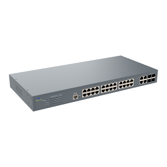
1.3 Front & Rear Panel Front Panel The front panel is configured as follows: 24 x 10/100/1000Base-T RJ-45 ports (Ports 1-24) 4 x Gigabit combo ports (Ports 25-28) : 4 x 10/100/1000Base-T RJ-45 ports, or 4 x 100/1000Base-X SFP ports Reset Button: ... -
Page 8: Network Management
Cable Type Description UTP Category 3, 4, 5 (100 meters max.) 10Base-T EIA/TIA- 568 150-ohm STP (100 meters max.) UTP Cat. 5 (100 meters max.) 100Base-TX EIA/TIA-568 150-ohm STP (100 meters max.) UTP Cat. 5e (100 meters max.) 1000Base-T UTP Cat. 5 (100 meters max.) EIA/TIA-568B 150-ohm STP (100 meters max.) 100BASE-FX Multi-mode fiber module(2km) / Single-mode fiber module... - Page 9 SNMP Management SNMP is also In-Band-Management and requires a network connection to the Managed Switch. The Managed Switch private Management Information Bases (MIB) is provided for SNMP-based network management program to configure, control and monitor the system. Web Management Web Management is done over the network. Once the Managed Switch is available on the network, you can login and monitor the status of it through a web browser remotely or locally.
-
Page 10: Installation
2. INSTALLATION To properly install the Managed Switch, please follow the procedures listed below. These procedures are described below in separate sections. Installation Requirements Unpacking the Managed Switch Installing the Managed Switch Power on the Managed Switch ... -
Page 11: Install The Managed Switch
If any item is found missing or damaged, please contact your local sales representative for support or replacement. 2.3 Install the Managed Switch CAUTION To prevent any damage or failure of the Managed Switch, please DO NOT block the ventilation FAN holes. Use the following guidelines when choosing a place to install the Switch: ... -
Page 12: Power On
The Managed Switch can be mounted in an EIA standard-sized, 19-inch rack, which can be placed in a wiring closet with other equipment. Rack mounting brackets are provided to mount the Switch. Procedure 1. Plan the rack position. 2. Attach the mounting bracket on the switch’s side panels (one on each side) and secure them with the screws provided. - Page 13 Power Failure In the event of power failure, unplug the power that is plugged into the switch at the back of the device. When power is resumed, plug the power back to the switch.
-
Page 14: Connect The Switch To Network
2.5 Connect the Switch to network Connect to Network The Managed Switch has 24 RJ-45 and 4 combo ports in front panel. These 24 RJ-45 ports can be plugged with 10/100/1000Base-T UTP connector. Uplink combo ports 25-28 can be plugged with 155Mbps, 1.25Gbps SFP Fiber transceiver or 10/100/1000Base-T UTP connector. -
Page 15: Operation
3. OPERATION The Managed Switch is Plug & Play compliant. Real-time operational status can be monitored through a set of LED indicators located in the front panel. A built-in management module provides users flexible interfaces to configure, control and monitor the complete system remotely. 3.1 LED Definitions Front Panel Power A/B LED... -
Page 16: Maintenance
Press the Reset button for 10 seconds and then release to reset Orange Blinking (back to factory settings) and restart the system. The LED indicator will blink in orange for three times. COM LED The console status is indicated by the Console LED on the front panel of the device. - Page 17 When the whole system fails to function, 1. Check Power LED status 2. Check Power connection 3. Reset power When certain network link fails to function, 1. Locate the port of the switch 2. Check LINK/ACT/Speed LED of the port 3.
-
Page 18: Hardware Replacement Procedures
4.2 Hardware Replacement Procedures WARNING! The Managed Switch contains no user-serviceable parts. DO NOT, UNDER ANY CIRCUMSTANCES, open and attempt to repair it. Failure to observe this warning could result in personal injury or death from electrical shock. Failure to observe the above warning will immediately void any Warranty.
Need help?
Do you have a question about the ESW-3128 Series and is the answer not in the manual?
Questions and answers