
Subscribe to Our Youtube Channel
Related Manuals for CTS EPS-3128 Series


Summary of Contents for CTS EPS-3128 Series
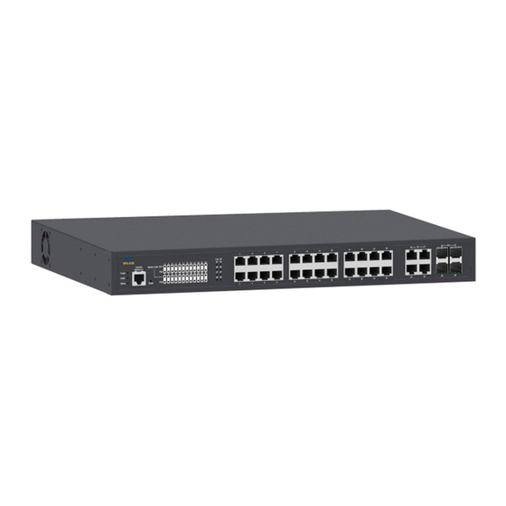
- Page 1 EPS-3128 Series 24 PoE+ 10/100/1000BASE-T RJ-45 PORTS WITH 4 COMBO PORTS (10/100/1000BASE-T, 100/1000BASE-X SFP) UPLINK MANAGEMENT SWITCH User’s Guide Version 0.90...
- Page 2 Trademarks CTS is a registered trademark of Connection Technology Systems Inc All trademarks belong to their respective proprietor Contents are subject to change without prior notice.
- Page 3 Revision History Version Date Description 0.90 20160124 First release...
-
Page 4: Table Of Contents
Table of Contents 1. INTRODUCTION ................... 5 1.1 The Managed Switch ................5 1.2 Key Features .................... 6 1.3 Front & Rear Panel ................... 7 1.4 Cable Specifications ................. 9 1.5 Network Management ................9 2. INSTALLATION ................... 11 2.1 Requirement ................... 11 2.2 Checking the Package Contents ............ -
Page 5: Introduction
1. INTRODUCTION The Managed Switch is designed to meet the emerging FTTX & Metro Ethernet requirement. Its low profile appearance with 1U height and standard rack- mount size achieves the highest density within a single rack. When massive fiber ports need to be deployed, the Managed Switch provides the best performance and price ratio. -
Page 6: Key Features
1.2 Key Features 19 inch, 1U high 24 x 10/100/1000BASE-T RJ-45 ports IEEE 802.3/802.3u/802.3ab/802.3z compliance Support MDI/MDIX/Auto-Crossover IEEE802.3at/af PoE/PSE Event Scheduling 4 x 10/100/1000Base-T ,100/1000Base-X Combo ports IEEE 802.3ab/802.3z Support Auto-Negotiation (RJ-45) and Auto-Sensing (SFP) Support MDI/MDIX/Auto-Crossover RJ-45 or SFP Slot ... -
Page 7: Front & Rear Panel
Rapid Spanning Tree Protocol (RSTP) Layer Link Discovery Protocol (LLDP) SFF-8472 (Digital Diagnostic Management Interface for SFP) IEEE 802.1X Authentication RADIUS Authentication for 802.1X DHCP Relay Agent with Option 82 IP Source Guard (Static IP, DHCP Snooping) DHCP Server Trust Port Loop Detection PoE Management Port Isolation... - Page 8 4 x 10/100/1000Base-T RJ-45 ports, or 4 x 100/1000Base-X SFP ports 24 x 10/100/1000BASE-T RJ-45 ports (Ports 1-24) 24 x 10/100/1000 PoE ports LED: Please refer to chapter 3.1 LED Definitions Reset Button: Pressing reset button for 5~10 seconds then release to restart the system.
-
Page 9: Cable Specifications
1.4 Cable Specifications The following table contains various cable specifications for the Managed Switch. Please make sure that you use the proper cable when connecting the Managed Switch. Cable Type Description UTP Category 3, 4, 5 (100 meters max.) 10Base-T EIA/TIA- 568 150-ohm STP (100 meters max.) UTP Cat. - Page 10 Telnet Management Telnet is done through the network. Once there is a network connection to the Managed Switch, users can use Telnet to configure, control and monitor the system. Using network connection to manage is often referred to In-Band- Management. SNMP Management SNMP is also In-Band-Management and requires a network connection to the Managed Switch.
-
Page 11: Installation
2. INSTALLATION To properly install the Managed Switch, please follow the procedures listed below. These procedures are described below in separate sections. Installation Requirements Unpacking the Managed Switch Installing the Managed Switch Power on the Managed Switch ... -
Page 12: Install The Managed Switch
If any item is found missing or damaged, please contact your local sales representative for support or replacement. 2.3 Install the Managed Switch CAUTION To prevent any damage or failure of the Managed Switch, please DO NOT block the ventilation FAN holes. Use the following guidelines when choosing a place to install the Switch: ... - Page 13 3. Allow adequate space for ventilation between the device and the objects around it. Rack Installation WARNING! Please mount the Switch firmly in rack otherwise it may be fall and cause the system damage and possible injury to personnel. The Managed Switch can be mounted in an EIA standard-sized, 19-inch rack, which can be placed in a wiring closet with other equipment.
-
Page 14: Power On
2.4 Power ON The Managed Switch can be used with AC power supply 100-240 VAC, 50 – 60 Hz or DC power supply 48V. The power switch is located at the rear of the unit adjacent to the power connector. After the Managed Switch is turned on, the Power LED indicators should light in green and the FAN should spin. -
Page 15: Connect The Switch To Network
2.5 Connect the Switch to network Connect to Network The Managed Switch has 24 PoE 10/100/1000BASE-T RJ-45 ports and 4 combo ports in front panel. These 24 PoE 10/100/1000BASE-T RJ-45 ports can be plugged with 155Mbps. Uplink combo ports 25-28 can be plugged with 155Mbps, 1.25Gbps SFP Fiber transceiver or 10/100/1000BASE-T UTP connector. -
Page 16: Operation
3. OPERATION The Managed Switch is Plug & Play compliant. Real-time operational status can be monitored through a set of LED indicators located in the front panel. A built-in management module provides users flexible interfaces to configure, control and monitor the complete system remotely. 3.1 LED Definitions Front Panel LED Indicators Power LED... -
Page 17: Maintenance
COM LED The console status is indicated by the Console LED on the front panel of the device. Color Operation Out-of-band management via console port is activated. Green When Console port is connected. Port LED 1~24 Color Operation No connection Green The link is up and the speed is in 100Mbps Link/ACT/Speed... - Page 18 Local Check Users can perform local check by observing LED indicators status or check system setup and configuration through console connection. When the whole system fails to function, 1. Check Power LED status 2. Check Power connection 3. Reset power ...
-
Page 19: Hardware Replacement Procedures
4.2 Hardware Replacement Procedures WARNING! The Managed Switch contains no user-serviceable parts. DO NOT, UNDER ANY CIRCUMSTANCES, open and attempt to repair it. Failure to observe this warning could result in personal injury or death from electrical shock. Failure to observe the above warning will immediately void any Warranty.
Need help?
Do you have a question about the EPS-3128 Series and is the answer not in the manual?
Questions and answers