
Subscribe to Our Youtube Channel
Related Manuals for Keysight Technologies PD1000A


Summary of Contents for Keysight Technologies PD1000A
- Page 1 Operating Guide Part of PD1000A Option -SPK Accessory Kit TO-220, TO-247, and Surface Mount Devices Keysight PD1000A Power Device Test Fixtures for S-Parameter Measurements...
- Page 3 WITHOUT NOTICE, IN FUTURE EDI- without prior agreement and written con- www.keysight.com/find/PD1000A TIONS. FURTHER, TO THE MAXIMUM sent from Keysight Technologies, Inc. as EXTENT PERMITTED BY APPLICABLE (product-specific information and sup- governed by United States and interna- LAW, KEYSIGHT DISCLAIMS ALL WAR- port, software and documentation tional copyright laws.
- Page 4 Safety Information Do Not Operate Near Flammable Do Not Modify the Instrument The following general safety precau- Liquids tions must be observed during all Do not install substitute parts or per- phases of operation of these instru- Do not operate the instruments in the form any unauthorized modification to ments.
- Page 5 Safety Symbols and Notices A CAUTION denotes a hazard. It calls attention to an operating pro- cedure or practice that, if not cor- rectly performed or adhered to, could result in damage to the product or loss of important data. Do not proceed beyond a CAUTION notice until the indicated condi- tions are fully understood and met.
-
Page 7: Table Of Contents
Inserting Devices into the TO-220 and TO-247 Test Fixtures ... 16 PD1000A Surface Mount Device Test Fixture ......17 Inserting Devices into the SMD Test Fixture. - Page 8 Keysight PD1000A Test Fixture Operating Guide...
-
Page 9: General Information
Preparation for Use The PD1000A Test Fixtures connect the device to be tested (DUT) to the Bias T Networks. Refer to Figure 1 on page 12 for a typical test setup. Licensing is required to use the PD1000A Power Device Measurement System Control Software for making On State and Off State S-Parameter measurement. -
Page 10: Associated Products
General Information Associated Products In addition to the three test fixtures, the PD1000A-SPK Accessory Kit includes the following items for S-Parameter measurements. Description Qty. Photos below are representative, what you receive may be different. 0.56 N-m (5 lb-in) 5/16 in. break-over torque wrench, Keysight 8710-1582 Type N, Male to SMA Female Adapter 50Ω... -
Page 11: Static-Safe Handling Procedures
Both types, when used together, provide a significant level of ESD protection. Of the two, only the table-mat and wrist-strap combination provides adequate ESD protection when used alone. To ensure user safety, the static-safe accessories must provide at least 1 MΩ of isolation from ground. Keysight PD1000A Test Fixture Operating Guide... -
Page 12: General Test Setup
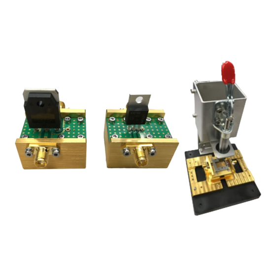
General Test Setup General Test Setup Figure 1 below shows the general test setup for the three PD1000A Test Fixtures (the Surface Mount Device (SMD) fixture is shown in the photo). Note the two PD1000A Bias T networks attached to the test fixture, the E5080A ENA Network Analyzer behind the test fixture, and the B2902A Precision SMU (on top of the E2080A ENA) providing bias voltage to the two Bias T networks. - Page 13 General Test Setup Use with PD1000A Bias T Networks Two Bias T devices are provided with the PD1000A Accessory Kit. Figure 2 shows the two PD1000A Bias T Networks ready to connect to a PD1000A TO-220 or TO-247 Test Fixture. Figure 3 shows the Surface Mount Device (SMD) Test Fixture.
- Page 14 B2902A Source Measure Unit (SMU). Channel 1 on the SMU (front panel) connects to the PD1000A Bias T for the RF input (Gate) to the device under test (DUT). Channel 2 on the SMU (rear panel) connects to the PD1000A Bias T for the RF output (drain or collector) of the DUT.
-
Page 15: Pd1000A To-220 And To-247 Device Test Fixtures
PD1000A TO-220 and TO-247 Device Test Fixtures PD1000A TO-220 and TO-247 Device Test Fixtures TO-220 and TO-247 device packages are generally designed as through-hole devices. Other package types, including the TO-257 (an hermetically sealed metal package that is otherwise equivalent to the TO-220) and the TO-262 PAK) package may also be tested with this fixture. -
Page 16: Inserting Devices Into The To-220 And To-247 Test Fixtures
PD1000A TO-220 and TO-247 Device Test Fixtures Inserting Devices into the TO-220 and TO-247 Test Fixtures Figure 7 below shows the proper orientation for inserting TO- style devices into the Test Fixtures. Always observe proper orientation when inserting devices. The sockets on the test fixture are spring-loaded to ensure proper contact with the device leads. -
Page 17: Pd1000A Surface Mount Device Test Fixture
PD1000A Surface Mount Device Test Fixture PD1000A Surface Mount Device Test Fixture Keysight’s PD1000A SMD Test Fixture is designed for testing surface mount device packages such as the 7-pin TO-263 (also known as D PAK or DDPAK) SMD devices. Other SMD devices may also be tested with the SMD Test Fixture. - Page 18 PD1000A Surface Mount Device Test Fixture When finished testing a device, lift up on the Test Fixture handle and carefully remove the DUT. If your SMD device does not have the pin-out shown below, or if your device has different dimensions than the standard device, you will need to create a custom frame and PC Board.
-
Page 19: Test Fixture Calibration
Required Equipment – E5080A ENA Network Analyzer used with your PD1000A Power Device Measurement System for Advanced Modeling – PD1000A Bias T Networks (quantity 2 required) –... - Page 20 The TO-220/TO-247 Calibration Standard kits have four devices labeled OPEN, SHORT, LOAD, and THRU. Figure 10 Calibration Standards for PD1000A TO-247 Test Fixture. Calibration Standards for the TO-220 fixture are similar but with narrower pin spacing. The SMD Calibration Standard kit has seven devices: Input Port Open (labeled GOP), Short (labeled GSH), 50Ω...
-
Page 21: Fixture Calibration Procedure
Test Fixture Calibration Fixture Calibration Procedure The PD1000A Test Fixtures were developed to test semiconductor devices with standard device packaging. Each fixture type has its own Calibration Standards kit. Calibration procedures for the PD1000A Test Fixtures are the same. Use the appropriate mechanical calibration standard devices supplied with your test fixture. - Page 22 The two Calibration Kit files (TO_Fixture_In.xkt for the Input Port and the TO_Fixture_*.xkt for the Output Port) are available from www.keysight.com/find/PD1000A. If you have not already done so, download these files directly to the E5080A hard drive (if it has an Internet connection) or onto a USB memory stick.
- Page 23 Gate Device Test Fixture (Surface Mount Device fixture shown) Figure 12 Calibration Setup for the PD1000A SMD Test Fixture. Setup for the TO-220/TO-247 Fixtures is similar. 3 Once all parameters have been set in the ENA, the calibration can be performed.
- Page 24 “Inserting Cal Standards into the PD1000A TO-220/TO-247 Test Fixtures” on page 27 and “Inserting the Cal Standards into the PD1000A SMD Test Fixture” on page 29 for detailed instructions on inserting the Calibration Standards. 9 Click Next. This opens the following screen: 10 Insert the Port 1 OPEN Cal Standard into the test fixture.
- Page 25 Standard goes between the Source/Emitter and Drain/Collector. Click Measure. Note: for the TO-220/TO-247 Test Fixtures, use the same SHORT Cal. Standard as before, but turn it around to fit into the correct sockets on the test fixture. Keysight PD1000A Test Fixture Operating Guide...
- Page 26 Cal Standard. Ensure that the displayed value is less than 0.2 nS. Click OK. 18 Click Save As User CalSet. Click Finish to complete the calibration procedure. 19 Remove the Calibration Standard from the Test Fixture. Keysight PD1000A Test Fixture Operating Guide...
-
Page 27: Inserting Cal Standards Into The Pd1000A To-220/To-247 Test Fixtures
Inserting Cal Standards into the PD1000A TO-220/TO-247 Test Fixtures Inserting Cal Standards into the PD1000A TO-220/TO-247 Test Fixtures Inserting Calibration Standards into the Test Fixtures is the same as inserting your device to be tested. This section shows the orientation of the Calibration Standards inserted into the Test Fixture. -
Page 28: Output Standards
Inserting Cal Standards into the PD1000A TO-220/TO-247 Test Fixtures Output Standards Two pins on each OPEN, SHORT, and 50 Ω LOAD Calibration Standards. These are the same standards used on the Input. The Calibration Standards connect between the Drain/Collector and Source/Emitter. -
Page 29: Inserting The Cal Standards Into The Pd1000A Smd Test Fixture
Inserting the Cal Standards into the PD1000A SMD Test Fixture Inserting the Cal Standards into the PD1000A SMD Test Fixture Use the Test Fixture PC Board, Vertically Conductive Sheet, and Frame Guide supplied with the SMD Test Fixture for fixture calibration. -
Page 30: Customizing An Smd Test Fixture
Detailed CAD files (.dxf) for the PC Board, the Frame Guide and Calibration Standards for standard MOSFET and IGBT devices are available as part of the PD1000A installation. You will also need to purchase a Keysight Frame. Figure 16 shows the primary components of the SMD Test Fixture. Refer to the following instructions. - Page 31 Fixture frame. Solder pads must extend to the edges of the board to permit soldering the frame SMA center connector pins to the PC board. Figure 18 below shows the microstrip line PC board provided with the PD1000A SMD Test Fixture. Yours will be different. TO-263-7 package shown for orientation and size reference.
- Page 32 ---- - ---- - ------------ - Ω ------ - ------ - ε Where: H=h-2t ε ε = Effective relative ε = Dielectric Constant = Characteristic impedance (use 50 Ω) Keysight PD1000A Test Fixture Operating Guide...
- Page 33 Frame Guide supplied with the SMD Test Fixture. You Frame Guide may vary. Screw holes are for M2 screws. Figure 20 PD1000A SMD Frame Guide Outside Dimensions. Inside dimensions are for a TO-263-7 package. TO-263-7 shown for orientation purposes. All dimensions in mm.
- Page 34 0 Ω SMD resistor (short) or 50 Ω SMD resistor must be placed on the top of the PC Board. Bottom view of PC board Pin 1 Gate Figure 21 Constructing the two 50 Ω SMD Cal Standards Keysight PD1000A Test Fixture Operating Guide...
- Page 35 Test Fixture, the Frame Guide holds the Vertically Conductive sheet in place. Assembling the Customized SMD Test Fixture 1 Place the PC Board on the PD1000A-SMD Test Fixture. The copper traces must face upward. Slide the PC board under the SMA connector center pins.
-
Page 36: Adjusting The Height Of The Push Rod
(Allen) set screw on the side of the push rod head and sliding the head up or down then tightening the set screw. See the figure below. Figure 24 Allen Screw to Adjust the Height of the Push Rod Keysight PD1000A Test Fixture Operating Guide... -
Page 37: Troubleshooting
Troubleshooting Troubleshooting This section provides a simple functional verification procedure to test the PD1000A Test Fixtures, cables, and Calibration Standards. This test procedures do not verify the resistance accuracy of the Calibration Standards. SMA Cables Do not excessively bend, flex, or stretch the SMA cables. Check the SMA cables regularly, and replace them if they are damaged in any way. - Page 38 PC board here, between the Drain/Collector and the Source/Emitter pads Measure resistance here, between the Gate (Pin 1) and the Source/Emitter pads Figure 27 Measuring the DC Resistance of the SMD Calibration Standards Keysight PD1000A Test Fixture Operating Guide...
-
Page 39: Use Proper Sma Connector Care And Connection Techniques
Very light finger pressure is enough to accomplish this. 7 Make sure the connectors are properly supported. Relieve any side pressure on the connection from long or heavy devices or cables. 8 Torque the connection according to the procedures described below. Keysight PD1000A Power Device Measurement System... -
Page 40: Final Connection Using A Torque Wrench
This is especially true when several devices are connected together. Refer to the following figure. Hold this wrench steady Lift Device Device Correct method Incorrect method (reduces lift on connection) (too much lift on connection) Figure 8 Wrench Positions Keysight PD1000A Power Device Measurement System... -
Page 41: Separating Connections
2 Use another open-end wrench or the torque wrench to loosen the connector nut. 3 Complete the separation by hand, turning only the connector nut. 4 Pull the connectors straight apart without twisting, rocking, or bending. Keysight PD1000A Power Device Measurement System... -
Page 42: Inspect And Clean Connectors
– Apply a small amount of isopropyl alcohol to a lint-free swab. Clean the connector threads. Let the alcohol evaporate, then blow the threads dry with a gentle stream of clean, low-pressure compressed air or nitrogen. Always completely dry a connector before you reassemble or use it. Keysight PD1000A Power Device Measurement System... - Page 44 This information is subject to change without notice. © Keysight Technologies, 2019 Printed in Malaysia Edition 3, January 2019 *PD1000-90005* PD1000-90005...
Need help?
Do you have a question about the PD1000A and is the answer not in the manual?
Questions and answers