
Related Manuals for Optex Accurance-3D A3001CB


Summary of Contents for Optex Accurance-3D A3001CB
- Page 1 Anti-Tailgate & Anti-Piggyback Sensor System Model : Control Box A3001CB : TOF Sensor A3001S Instruction guide (Version 0.01)
-
Page 2: Pictorial Indication
Before your operation Read this instruction guide carefully prior to installation and operation. After reading, store this guide carefully in an easily accessible place for reference. Pictorial indication This guide uses the following warning indications for correct use of the project, harm to you or other people and damage to your assets, which are described below. -
Page 3: Inform A Building Owner Or Facility Manager
To reduce the risk of injury Be careful with your fingers when closing the cover of the control box. To reduce the risk of failure. Do not use the products under environments with extreme humidity, oil, smoke, dust and any severe vibration. Do not stand or put any heavy objects on the products. -
Page 4: Precautions
Software licensed based on GNU General Public License (GPL) is included in this product. We obtain a source code of the software concerned and, according to GPL reproduce it and distribute it and can modify the visitor. Please contact us for the open source code using with this product. Copyrighted (C) 2015 OPTEX.CO,.LTD... -
Page 5: Definition Of Terms
Definition of terms The following terms are important to know in order that the product works properly. Secured area Area with entry limitation by an authorization device. Interlock area Area in interlock. Non-secured area Area with no entry restrictions ... -
Page 6: Table Of Contents
Table of contents Before your operation ..........................i Pictorial indication ..........................i Document disclaimer ..........................i Inform a building owner or facility manager ....................ii Precautions .............................. iii Copyright ............................iii Definition of terms ............................ iv Introduction ............................7 1-1 Features .............................. - Page 7 Output status ............................ 39 Installer logout ..........................40 3-4 Operation checking ........................... 40 3-5 Event log recording function ......................41 Output log / delete log ........................42 3-6 Sound function ..........................43 Appendix ............................. 44 4-1 Outer dimensions ..........................44 4-2 Specifications ............................
-
Page 8: Introduction
1 Introduction 1-1 Features A3001 is Anti-Tailgate & Anti-Piggyback Sensor System that uses Time Of Flight technology. This product can only be incorporated with the size limited outward opening Interlock door. Note that the product does not prevent unauthorized entry physically. Control Box is accessible to up to two TOF Sensor, it can be used for both direction One way (only entry) and Two way (entry and exit) The product is designed to register only and therefore not to prevent property loss and casualty, or physical... -
Page 9: Tof Sensor A3001S
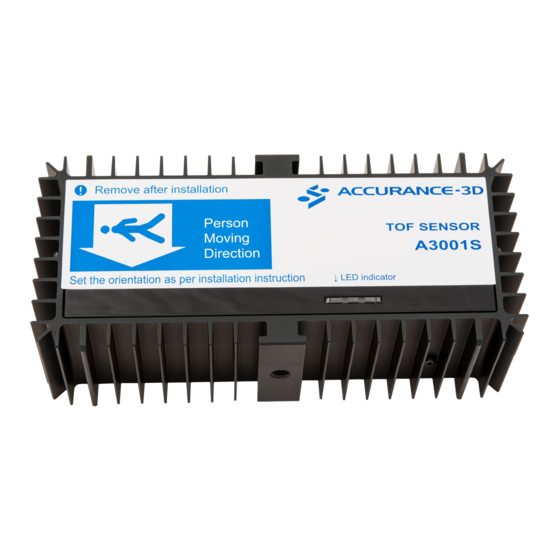
TOF Sensor A3001S Ferrite core (2pcs) Sensor power cable TOF Sensor A3001S Mounting screws Wire connector (4pcs) (2pcs) Fig 1-2 1-3 System example for A3001 Door2 control Magnet contact Zero Control Authorization device for More Sensor entry Access Suspicious Control LAN1 System... -
Page 10: Part Names
1-4 Part Names Control box Screw Power Indicator Power Switch Top Case Power Input terminals Sound jack Power Supply sockets USB 2.0 LAN Connector Front Case for TOF Sensor (2) Fig 1-4 Power Indicator Operation Indicator Power Switch Input Output Primary Secondary... -
Page 11: Tof Sensor
TOF sensor Power indicator (Green) Operation indicator Power input socket LAN connector (3 colors) Front side Back side Fig 1-6... -
Page 12: Mounting And Wiring
2 Mounting and wiring 2-1 Mounting TOF sensor Mounting position of TOF Sensor The mounting position of TOF Sensor changes by a use (One way or Two way) and size of interlock area as shown as below; For One way ... - Page 13 Interlock area over 1.5 m×1.0 m (W×D) Presence sensor (AIR input) is necessary Presence TOF Sensor sensor area direction [Secured area] Entry [Non-secured area] Center ±0.1 m Fig 2-2 Note: Detection area need to be overlapped each other Table 2-2 Mounting height 2.3 m 2.6 m...
- Page 14 For Two way Interlock area within 1.5 m×1.5 m (W×D) Detection area Authorization overlap length device for = 0.5 m entry [Secured area] Exit Entry [Non-secured area] Authorization TOF Sensor direction device for exit Center ±0.1 m Fig 2-3 Table 2-3 Mounting height 2.3 m...
- Page 15 Interlock area over 1.5 m×1.5 m (W×D) Presence sensors(AIR input) are necessary Presence sensor area [Secured area] Exit Entry [Non-secured area] TOF Sensor direction Center ±0.1 m Fig 2-4 Table 2-4 Mounting height 2.3 m 2.6 m 2.9 m 1.0 m max.
-
Page 16: How To Mount Tof Sensor
How to mount TOF Sensor TOF Sensor must be mounted on a ceiling with no dealing facing the floor downward. (90 degree vertically to the floor) <Note> TOF sensor must be oriented as Fig 2-1, Fig 2-2, Fig 2-3 and Fig 2-4. The allow mark on TOF Sensor is indicated in the figures. - Page 17 Screw hole Do not put anything Sensing area 50° 70° Fig 2-7 If mounting height is lower than 2.3 m, make mounting jig as shown in Fig 2-8. <Note> This figure is only for reference. Screw hole Do not put anything Sensing area 50°...
-
Page 18: Mounting Control Box
2-2 Mounting Control Box Disassembling top case Turning the screw on the upper side of body. ※The screw does not come off. Fig 2-9 Remove top case as shown in Fig 2-10 Fig 2-10... -
Page 19: Assembling Front Case
Assembling front case Front Case can be used in 2 ways by assembly direction. For front wiring. Fig 2-11 For back wiring. Fig 2-12... -
Page 20: How To Mount Control Box
How to mount Control Box Hook hole Drill a hook hole and two mounting holes as shown in Fig 2-13. (mounting template) Please prepare three screws or three anchors depending on the mounting Mounting holes wall. Screw size 5 mm dia. max. [mm] Fig 2-13 Making a hook. -
Page 21: Wiring
2-3 Wiring Wiring example of A3001 One way Input Output Primary Secondary Common Primary Secondary Operation indicator Primary Power input Secondary 24 VDC GND Power input 24 VDC TOF Sensor AIR Sensor Access control system Interlock controller Authorization Door device Fig 2-16... -
Page 22: Input/Output Terminals
Input/output terminals Input Output Primary Secondary Common Primary Secondary I/O indicator Input terminals (10) Output terminals (16) Fig 2-18 Wire specification Please refer to the chart below as to usable wire rod and length of stripping the cable sheath Stripped length 9 to 10 mm Fig 2-19... - Page 23 Please make a power cable for TOF Sensor from Control Box using addition a cable(AWG22)(not provided) The length of the additional cable should be fitted the distance between Control Box and TOF Sensor. Fig 2-20...
-
Page 24: Wiring Between Control Box And Tof Sensor
Wiring between Control Box and TOF Sensor Connect Control Box and TOF Sensor with Ethernet Cable (not provided) and Sensor Power Cable (provided) Prepare Sensor Power Cable and Ethernet Cable. *Please set ferrite to the both end of the Ethernet Cable. -
Page 25: Led Indications
2-4 LED indications LED indications of Control Box Power indicator Operation indicator (Green) (Green, Red, Blue) Operation indicator Primary Power input Secondary 24 VDC GND Fig 2-24 Power indicator Mode Status Indicating Operation Power ON Green Operation indicators Mode Status Indicating... -
Page 26: Led Indications Of Tof Sensor
LED indications of TOF Sensor Power indicator Operation indicators (Green) (Green, Red, Blue) Front side Back side Fig 2-25 Power indicator Mode Status Indicating Operation Power ON Green Operation indicators Mode Status Indicating 1 sec 1 sec 1 sec Green During power up... -
Page 27: Setting Detection Area And Sensitivity
3 Setting detection area and sensitivity 3-1 Connection to PC Before initial setting This product is installed and configured through wired LAN (Ethernet). Separately prepare a Windows PC and LAN cable for configuration of settings (installation). And when use two units of TOF Sensor, prepare Ethernet hub. -
Page 28: Pc Setting
3-2 PC setting TCP/IP Before setting Control Box, configure the LAN (TCP/IP) setting of your PC as follows; Proxy setting : Disable Wired LAN : Enable Wireless LAN : Disable <Notes> Only one wired LAN should be used, or it may cause problems. ... -
Page 29: Pc Network Setting
PC network setting Click Control Panel -> Network and Internet -> view network status and tasks -> Local Area Connection, and show the status of Local Area Connection. Click Properties of Local Area Connection Status. Select Internet Protocol Version 4 (TCP/IPv4) of Local Area Connection Status Properties, and click Properties. -
Page 30: Start-Up Remote Desktop Connection
Select Obtain an IP address automatically and Obtain DNS server address automatically of Internet Protocol Version 4 (TCP/ IPv4) Properties, and click OK. Start-up Remote Desktop Connection Click All Programs -> Accessories -> Remote Desktop Connection from Start menu. - Page 31 Or, input “mstsc” to Search programs and files of Start menu. Input ‘192.168.2.250’ to Computer: of Remote Desktop Connection, and click Connect. Select Don`t ask me again for connections to this computer, and click Yes. Input ‘Administrator’ to User name, “accurance” to Password, and click OK.
-
Page 32: Automatic Log On Of Remote Desktop Connection
After Log On, the screen changes to ACCURANCE-3D application. *For ACCURACE-3D application setting, see “Initial Setting of ACCURACE-3D application”. Automatic log on of Remote Desktop Connection Reconnection of Remote Desktop Connection is necessary at the time of setting of the ACCURACE-3D application. -
Page 33: Remove Of Remote Desktop Connection
When asked “Do you trust this remote connection?”, select Don’t ask me again for connections to this computer, and click Connect. Input ‘accurance’ to Administrator Password, click OK. Remove of Remote Desktop Connection Click X of Remote Desktop Connection in the corner on the upper right. When asked “Remote Desktop Connection”... -
Page 34: Initial Setting Of Accurace-3D Application
3-3 Initial setting of ACCURACE-3D application Date & Time adjustment Firstly, adjust the time. Click ‘Adjust’ Click Time Zone, and the following figure below appears. Select the Area and click Apply. Return to Date & Time, please confirm the setting of date and time. *Date and time can also be changed later. -
Page 35: Installer Setting
Installer setting After restart Control Box, click option as shown in the figure on the below. Click Installer Login as shown in the screen on the right. After typing the password, press OK on the password-typing screen. After Login “Login successful” appears, click OK Password is “1111”... - Page 36 When logged in, and the background of the screen becomes blue, and the buttons are added. When using two units of TOF Sensor, please check that Primary and Secondary are set respectively for each TOF Sensors. When not correctly set, click button of “Swap primary and secondary”.
-
Page 37: Setting Detection Area
Setting detection area < Before Position Setting > Sensor Direction Select the direction of the sensor. Select whether the installation is for detection from the non-secured side to the secured side or from the secured side to the non-secured side. ... -
Page 38: Security Settings
Security settings < Parameter Setting > <Note> Default setting is All = 5 ※the factory settings for all controls are 5. This product has six sensitivity adjustments: Volume, Moment, Low object, Sensor Blinding, One person and More persons. All sensitivity controls have the options of 1 to 9 and the factory settings for all controls are 5. Changing these settings allows the adjustment of piggy-backing sensitivity. - Page 39 Table 3-1 Parameter HIGH Remarks Volume Description Total size of person/object in the door The piggyback detection is influenced more by other parameters Advantage / Better detection for two persons Less rejection of big person such as "More persons" and "Moment" when choosing Low. Way to Adjust Consequence More rejection of big person...
-
Page 40: Output Status
Output status This product counts each output. Authorization When an authorization signal is received from door controller, the background color turns into red. It shows the number of authorization. Zero, One, More, Sus Each background color is changed by output result. It shows the number of output. -
Page 41: Installer Logout
Installer logout When finish all settings, click the button of “Installer Logout”. When logged out, and the background of the screen becomes gray, and the three buttons will be disappeared. 3-4 Operation checking Table 3-2 Output Condition Indicator LED Control Box(A3001CB) TOF Sensor(A3001S) Stand by... -
Page 42: Event Log Recording Function
3-5 Event log recording function An event log will be generated and stored on the ACCURANCE-3D control box SSD as a video file, in the following format. Data Recording will start one second before the door opening and end one second after the output signal is generated on the A3001CB. -
Page 43: Output Log / Delete Log
Output log / delete log This product records authorization logs with capture data. <Note> As capturing video is heavy load do not set it unless necessary. Logging Setting Select ‘Capture’ or ‘Still’ both for PRIMARY and SECONDARY, and select the output result “Zero” “One” “More”... -
Page 44: Sound Function
3-6 Sound function When connecting a speaker to the 3.5 mm output mini-jack located on the A3001CB, you can use the following sounds functions when activated. Output Sound Dingdon More Bzzzzzzz Suspicious Bzzzzzzz... -
Page 45: Appendix
4 Appendix 4-1 Outer dimensions Control Box A3001CB [mm] TOF Sensor A3001S [mm]... -
Page 46: Specifications
4-2 Specifications Control box Items Specifications Remarks Model No. A3001CB 24±10% VDC Power input Current draw 840 mA max. (24 VDC) Excluding TOF Sensor Including two units of TOF 2520 mA max. (24 VDC) Sensors -10℃ to +50℃ Operating temperature Operating humidity 0% to 80% No condensation... - Page 47 16 normally open outputs. 30 VDC 0.2 A max. Resistibility Load. 1 Zero 2 One 3 More 4 Suspicious Primary 5 AIR 6 Heartbeat Output terminals 9 Zero 10 One 11 More 12 Suspicious Secondary 13 AIR 14 Heartbeat 15 - 16 - 210×250×91 mm (H×W×D) Dimensions...
-
Page 48: Tof Sensor
TOF sensor Items Specifications Remarks Model No. A3001S Power input 24 VDC Supplied from Control Box Current draw 840 mA max. (24 VDC) -10℃ to +50℃ Operating temperature Operating humidity 0% to 80% No condensation Installation location Indoor Applicable door Outward opening interlock door Detection method Time Of Flight... -
Page 49: Signal Diagram
4-3 Signal diagram Heartbeat output makes a 0.33 Hz signal as a heartbeat signal Power-up 60 to 120 sec 1 sec or less Zero More Suspicious Heartbeat Time Power ON Starting up complete Output Signal Timing Door1 Close Open Close (Activation) - Page 50 Shutdown More than 45 sec Power supply 20 to 40 sec More than 2 sec Shutdown Operation Heartbeat Time Shutdown sequence start Power off Time-out function Door Close Open Close Open Open/Close Door1 Unlock Lock Unlock Lock Lock/Unlock Indication “Please leave immediately”...
-
Page 51: Troubleshooting
4-4 Troubleshooting Problem Check if… Corrective action Does not operate Power indicator (green LED) of Check the wiring between TOF Control Box and TOF Sensor is Sensor and Control Box. See ”Wiring” Check the switch of Control Box is turned on. Check the switch of door system is turned on. - Page 52 Problem relating to Log Cannot record Log / no logged file SSD is set Check the connection of SSD. saved Logging is set Check the setting of Logging See ”Output Log / Delete Log” The memory of SSD is full Delete existing log files.
-
Page 53: How To Remove Battery Safely
4-5 How to remove battery safely Control Box has a button-type battery on inside material. When you replace and/or dispose the battery, please see below; And, make sure turn off the power of the Control Box and disassemble wirings. Disassemble 5 screws as shown in the figure on the left. - Page 54 Instruction guide version 0.01 DEC 2015 59-****-0...
Need help?
Do you have a question about the Accurance-3D A3001CB and is the answer not in the manual?
Questions and answers