Advertisement
Quick Links
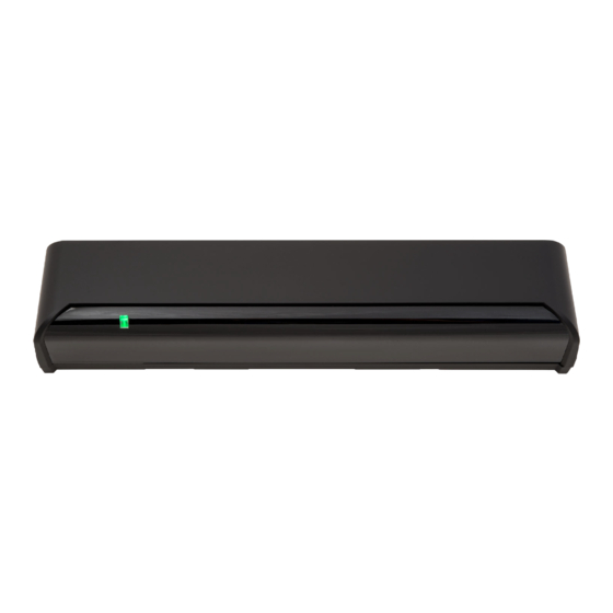
OA-4500S(E)
MANUFACTURER'S STATEMENT
MANUFACTURER'S STATEMENT
Read this operation manual carefully before use to ensure proper operation of this product.
Failure to read this operation manual may cause improper operation and may result in serious injury or
death of a person.The meanings of the symbols are as follows.
Disregard of warning may cause the improper operation causing death or serious injury of
WARNING
a person.
Disregard of caution may cause the improper operation causing injury of a person or damage to
CAUTION
objects.
NOTE
Special attention is required to the section of this symbol.
NOTE
1. This product is a non-contact switch intended for header mount to use on industrial doors.
Do not use for any other applications.
2. When setting the sensor's detection area, make sure that there is no traffic around the installation site.
3. Before turning the power ON, check the wiring to prevent damage or malfunction of equipment connected to
the product.
4. Only use the product as specified in the operation manual provided.
5. Be sure to install and adjust the sensor in accordance with the local laws and standards of the country in which
the product is installed.
6. Before leaving the installation site make sure that the product is operating properly and instruct the building
owner/operator on proper operation of the door and the product.
7.The product settings can only be changed by an installer or service engineer. When changed, the changed
settings and the date shall be registered in the maintenance logbook accompanying the door.
WARNING
Do not wash, disassemble, rebuild or repair the sensor, otherwise
it may cause electric shock or breakdown of the equipment.
Danger of electric shock.
NOTE
The following conditions are not suitable for sensor installation.
-Fog or exhaust emission around the door.
-Wet floor.
-Vibrating header or mounting surface.
-Moving objects or objects that emit light near the detection area.
-Highly reflecting floor or highly reflecting objects around the door.
SPECIFICATIONS
Model
: OA-4500S(E)
Color
: Black
Mounting Height
: 2.5m(8'2") to 4.5m(14'9)
Detection area
: See DETECTION AREA
Detection method
: Active infrared reflection method
(All presence detection)
Depth adjustment
: 1st to 3rd rows: -6° to +6°
4th and 5th rows: +26° to +44°
Power supply
: 12 to 24V AC ±10% (50/60Hz)
12 to 30V DC ±10%
Power consumption
: < 2.5W (< 4VA at AC)
Operation indicator
: Green / Stand-by
Red / 1st row detection
Orange / 2nd to 5th rows detects
NOTE
The specifications herein are subject to change without prior notice due to improvements.
OUTER DIMENSIONS AND PART NAMES
267(10 1/2")
125(4 15/16")
36(1 7/16")
43(1 11/16")
(1)
(2)
(3)
(4)
(5)
All manuals and user guides at all-guides.com
ENGLISH
ORIGINAL
Activation output
: When 3rd, 4th or 5th row detects.
N.C. / N.O. selectable
50V0.3A MAX.(Resistance load)
Safety output
: When 1st or 2nd row detects.
N.C. / N.O. selectable
50V0.3A MAX.(Resistance load)
Output hold time
: Approx. 0.5 sec.
Response time
: <0.3 sec.
Operation temperature
: -20°C to +55°C(-4°F to 131°F)
: <80%
Operating humidity
IP rate
: IP54
Weight
: 320g(11.3oz)
Accessories
: 1 Cable 4m(13'2")
2 Mounting screws
1 Mounting template
1 Operation manual
1 Area adjustment tool
45(1 3/4")
[mm(inch)]
(8)
(1) Connector
(2) Mounting holes
(3) Operation indicator
1 2 3 4
5
6 7 8
9 10 11 12
13
14
15
16
(4) Depth angle adjustment screw
(5) Width adjustment screws
(6) Dipswitches
(7) Detection window
(6)
(7)
(8) Area adjustment tool
DETECTION AREA
Z
A
1st row
B
2nd row
3rd row
4th row
5th row
F
G
: Emitting spots
: Detection Area
: Emitting spots (Can be eliminated)
NOTE
The actual detection area may become smaller depending on the ambient light, the color / material of
the object or the floor as well as the entry speed of the object.
The sensor may not be activated when the entering speed of the object or a person is slower than
50mm / sec. or faster than 1500mm / sec.
INSTALLATION
1
Affix the mounting template at the desired
mounting position.
Drill two mounting holes ø3.4mm (ø1/8") on
the header.
To pass the cable through the header,
drill a wiring hole of ø8mm (ø5/16").
The lower edge
of the header
2
Wire the cable to the door controller as shown below.
Activation output
Safety output
WARNING
Before starting the procedure, make sure that the power is turned OFF.
When passing the cable through the hole, do not tear the shield
Danger of electric shock.
otherwise it may cause electric shock or breakdown of the sensor.
3
1.Plug the connector of the sensor.
2.Supply power to the sensor.
3.Adjust the detection area and set the dipswitches. (See ADJUSTMENTS)
Make sure to connect the cable correctly to the door controller before turning the power ON.
NOTE
When turning the power ON or after adjusting the settings, do not enter the detection area for more
than 10 seconds in order to enable the presence detection.
4
Place the housing cover.
If wiring is to be exposed, break the knockout.
Do not use the sensor without the cover.
WARNING
When using the cable knockout, install the sensor
Danger of
indoors or use the rain-cover (Separately available)
electric shock.
otherwise electric shock or breakdown of the sensor may occur.
ADJUSTMENTS
1
Area depth angle adjustment
Depth angle
adjustment screw
Make sure that the detection area does not overlap with the door / header, and there is no highly reflecting
NOTE
object near the detection area otherwise ghosting / signal saturation may occur.
1-1.Independent adjustment
1st to 3rd rows
Use the area adjustment tool (A) as shown below to change the area depth angle for the 1st to 3rd rows.
Shallow
Deep
2.0
(6'7")
Depth angle adjustment screw
3.0
for the 1st to 3rd rows
(9'10")
4.0
(13'2")
4.5
Red
4.0
3.0
(14'9")
(13'2")
(9'10")
4th and 5th rows
Use the area adjustment tool (B) as shown below to change the area depth angle for the 4th and 5th rows.
Shallow
Deep
2.0
(6'7")
3.0
Depth angle adjustment screw
(9'10")
for the 4th and 5throws
4.0
(13'2")
4.5
4.0
3.0
(14'9")
Blue
(13'2")
(9'10")
1-2.Simultaneous adjustments
Use the area adjustment tool (C) as shown below to change the area depth angle for all rows.
Shallow
Deep
2.0
(6'7")
3.0
(9'10")
Deep
4.0
(13'2")
4.5
4.0
3.0
(14'9")
(13'2")
(9'10")
C D
E
250
300
350
400
Z
(10")
(12")
(1'2")
(1'4")
Values of the chart are based on the
1st to 3rd rows :
following depth angle adjustment settings;
4th and 5th rows:
[mm(inch)]
125(4 15/16")
36(1 7/16")
Wiring hole
ø8mm (ø5/16")
25(1")
Mounting holes
ø3.4mm (ø1/8")
12 to 24V AC (50/60Hz)
12 to 30V DC
See ADJUSTMENTS 3-9 for output settings.
Knockout.
Area adjustment tool
A
B
C
[mm(feet,inch)]
Deep
Shallow
Deep
Shallow
2.0
(6'7")
3.0
(9'10")
4.0
(13'2")
4.5
2.0
1.0
0
2.0
1.0
0
(14'9")
(6'7")
(3'3")
(6'7")
(3'3")
[mm(feet,inch)]
Deep
Shallow
Deep
Shallow
2.0
(6'7")
3.0
(9'10")
4.0
(13'2")
4.5
2.0
1.0
0
2.0
1.0
0
(14'9")
(6'7")
(3'3")
(6'7")
(3'3")
[mm(feet,inch)]
Shallow
Deep
Deep
Shallow
2.0
(6'7")
3.0
(9'10")
4.0
(13'2")
4.5
2.0
1.0
0
2.0
1.0
0
(14'9")
(6'7")
(3'3")
(6'7")
(3'3")
450
(1'6")
1.0
(3'3")
1.0
(3'3")
1.0
(3'3")
Advertisement

Related Manuals for Optex OA-4500S


Summary of Contents for Optex OA-4500S
- Page 1 Danger of indoors or use the rain-cover (Separately available) electric shock. otherwise electric shock or breakdown of the sensor may occur. SPECIFICATIONS Model : OA-4500S(E) Activation output : When 3rd, 4th or 5th row detects. ADJUSTMENTS Color : Black N.C. / N.O. selectable Mounting Height : 2.5m(8’2”) to 4.5m(14’9)
- Page 2 European Subsidiary The activation and safety outputs can be selected separately ( N.C. or N.O. by dipswitch 13 and 14 ) OPTEX Co.,LTD. OPTEX Technologies B.V. 5-8-12 Ogoto Otsu 520-0101, Japan Henricuskade 17, 2497 NB The Hague,The Netherlands TEL.: +81(0)77-579-8700 FAX.: +81(0)77-579-7030...
Need help?
Do you have a question about the OA-4500S and is the answer not in the manual?
Questions and answers